Medium Voltage Power Cable (MV Power Cable): Complete Technical Specifications and Selection Guide
Medium Voltage Power Cable (MV Power Cable): Complete Technical Specifications and Selection Guide
Medium Voltage (MV) power cables are essential components in power transmission and distribution systems, widely used across 6kV to 35kV voltage classes in grid construction, industrial power distribution, renewable energy projects, and infrastructure development. With the global grid upgrade and large-scale deployment of renewable energy, the demand for high-quality MV power cables continues to grow. This comprehensive guide covers technical specifications, construction design, industry standards, application scenarios, and selection criteria.
1. Definition and Voltage Classification
According to IEC standards, MV power cables typically range from 3.6/6kV to 26/35kV rated voltage. Voltage classifications vary slightly across standards:
| Standard System | MV Range | Typical Rated Voltages (U₀/U) |
|---|---|---|
| IEC 60502-2 | 3.6/6kV ~ 26/35kV | 6/10kV, 8.7/15kV, 12/20kV, 18/30kV, 26/35kV |
| IEEE/ANSI | 5kV ~ 46kV | 5kV, 8kV, 15kV, 25kV, 35kV, 46kV |
| BS 6622 | 3.8/6.6kV ~ 19/33kV | 6.6kV, 11kV, 33kV |
| China GB/T 12706.2 | 3.6/6kV ~ 26/35kV | 6/10kV, 8.7/15kV, 12/20kV, 18/30kV, 26/35kV |
Where U₀ is the rated voltage between conductor and earth (metallic shield), and U is the rated voltage between conductors.
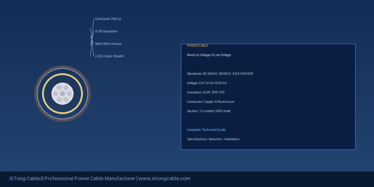
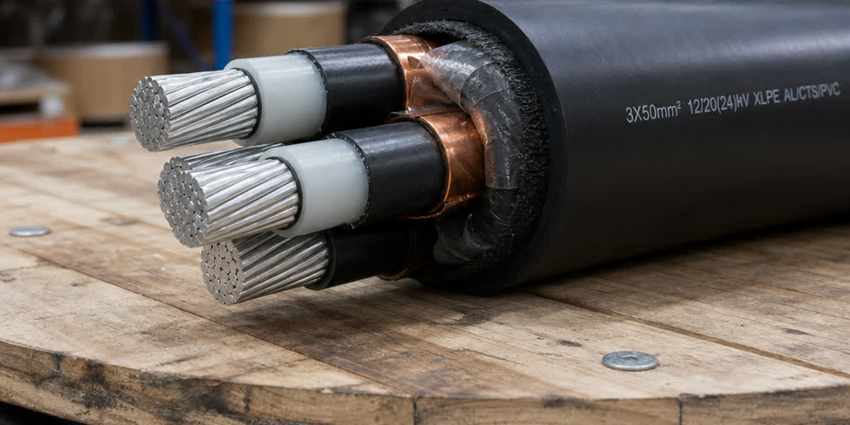
2. MV Power Cable Construction Layers
MV power cables have a more complex structure than LV cables, comprising the following key layers:
2.1 Conductor
- Materials: Copper (Cu) or Aluminum (Al)
- Shape: Circular compact stranded (Class 2 per IEC 60228)
- Cross-section range: 25mm² ~ 1600mm² (common: 50mm² ~ 630mm²)
2.2 Conductor Screen (Semiconducting Layer)
- Extruded semiconducting layer that ensures uniform electric field distribution and prevents partial discharge
- Typical thickness: 0.5-0.8mm
2.3 Insulation
- Material: Cross-linked Polyethylene (XLPE) is the dominant choice, with EPR (Ethylene Propylene Rubber) and HEPR as alternatives
- Thickness: Voltage-dependent (e.g., 8.7/15kV ~ 4.5mm, 26/35kV ~ 8.0mm)
- Key properties: High dielectric strength, low dielectric loss, excellent thermal aging resistance
2.4 Insulation Screen
- Extruded semiconducting layer + metallic shield
- Ensures zero potential at the insulation boundary and carries fault current
2.5 Metallic Shield
- Types: Copper tape shield, copper wire braid, or corrugated copper tape
- Functions: Carries short-circuit current, provides ground return path, electromagnetic shielding
- Cross-section: Calculated based on system fault current, typically 16mm² ~ 50mm² Cu equivalent
2.6 Fillers & Binder Tape
- Required for multi-core cables to maintain circular geometry
2.7 Inner Sheath
- Extruded PVC or Low-Smoke Zero-Halogen (LSZH) material
2.8 Armour
- Steel Tape Armour (SWA/STA): For direct burial or mechanical protection
- Steel Wire Armour (SWA): For tensile load applications (vertical installations, underwater)
- Aluminum Wire Armour (AWA): For single-core cables to avoid iron losses
2.9 Outer Sheath
- Materials: PVC, PE, LSZH, HFFR (Halogen-Free Flame Retardant)
- Colors: Black (outdoor), Red (flame retardant), Blue (LSZH)
3. Technical Parameter Comparison
| Parameter | 8.7/15kV XLPE | 12/20kV XLPE | 18/30kV XLPE | 26/35kV XLPE |
|---|---|---|---|---|
| Max system voltage | 17.5kV | 24kV | 36kV | 40.5kV |
| Insulation thickness | 4.5mm | 5.5mm | 5.5mm | 8.0mm |
| Conductor screen thickness | ≥0.6mm | ≥0.6mm | ≥0.7mm | ≥0.8mm |
| Insulation screen thickness | ≥0.6mm | ≥0.6mm | ≥0.7mm | ≥0.8mm |
| Partial discharge test | <5pC @ 9kV | <5pC @ 12kV | <5pC @ 18kV | <5pC @ 26kV |
| AC withstand voltage | 25kV/5min | 35kV/5min | 45kV/5min | 62kV/5min |
| Bending radius (single-core) | 15×D | 15×D | 15×D | 15×D |
| Bending radius (three-core) | 12×D | 12×D | 12×D | 12×D |
Note: D = cable outer diameter
4. MV vs LV vs HV Power Cables
| Aspect | LV Cable | MV Cable | HV Cable |
|---|---|---|---|
| Voltage range | ≤1kV | 3.6/6kV ~ 26/35kV | >35kV (66kV, 110kV, 220kV) |
| Insulation layers | No screens | Conductor + insulation screens | Complex screens + buffer + water blocking |
| Insulation material | PVC, XLPE | XLPE (dominant) | XLPE (dominant) |
| Metallic shield | Usually not required | Mandatory | Mandatory (corrugated Al sheath) |
| Installation | Relatively simple | Requires professional terminations | Extremely strict installation |
| Typical applications | Building wiring, distribution panels | Distribution networks, industrial plants | Transmission backbone |
5. Application Scenarios
5.1 Power Distribution Networks
- Underground urban distribution grid upgrades
- Industrial park and development zone distribution
- Substation incoming and outgoing feeders
5.2 Industrial Applications
- Steel plants, chemical plants, refineries
- Mining power systems
- Cement plants, paper mills
5.3 Renewable Energy
- Solar PV power plants: 35kV collector circuits
- Wind farms: 35kV inter-array and transmission cables
- Battery energy storage: MV grid interconnection
5.4 Infrastructure
- Airport and harbor power supply
- Metro/rail transit power distribution
- Large commercial complexes
- Data centers
5.5 Marine Applications
- Offshore wind platform interconnection
- Offshore oil platform power supply
- Subsea MV distribution networks
6. International Standards & Certifications
When selecting MV power cables, ensure compliance with these standards:
| Standard | Scope | Key Requirements |
|---|---|---|
| IEC 60502-2 | MV cables 3.6/6kV to 26/35kV | Dimensions, electrical performance, test methods |
| IEC 60228 | Conductors | Stranded conductor resistance classes |
| IEC 60332-1/3 | Flame retardancy | Single/bunched flame test |
| IEC 60754 | Halogen content | Halogen-free requirements |
| IEC 61034 | Smoke density | Low smoke performance |
| IEEE 48 | MV cable terminations | Testing standards |
| AEIC CS8 | MV XLPE cables | US industry specification |
| BS 6622 | MV XLPE cables (UK) | British standard |
7. MV Power Cable Selection Guide
7.1 Voltage Rating Selection
Choose the correct U₀/U rating based on system voltage: - 10kV grid → 8.7/15kV or 6/10kV - 20kV grid → 12/20kV - 33kV grid → 19/33kV - 35kV grid → 26/35kV
7.2 Conductor Size Selection
Based on current-carrying capacity, voltage drop, and short-circuit rating: - Continuous current rating: Consider installation method (air/direct burial/tray/duct), ambient temperature, and grouping derating factors - Short-circuit rating: Must satisfy thermal stability under maximum system fault current
7.3 Metallic Shield Sizing
Determine minimum shield cross-section based on system single-phase-to-ground fault current and fault duration.
7.4 Sheath Material Selection
- Direct burial outdoors → PE sheath (moisture and corrosion resistant)
- Indoor/tunnel → LSZH sheath (fire safety)
- Chemical plants/coastal → Special corrosion-resistant sheath
7.5 Armour Selection
- Direct burial → Steel tape armour (SWA/STA)
- Vertical or high-drop installations → Steel wire armour (SWA)
- Single-core cables → Non-magnetic armour (aluminum or stainless steel)
7.6 Fire Rating
Based on project fire safety requirements: - General → IEC 60332-1 single flame retardant - High-risk areas → IEC 60332-3 bunched flame retardant (Cat A, B, C, D) - Halogen-free low smoke → LSZH (IEC 60754 + IEC 61034)
8. FAQ
Q1: What is the fundamental difference between MV and LV cables?
MV cables incorporate both conductor and insulation screens (semiconducting layers + metallic shield), while LV cables typically have no screens. The screens ensure uniform electric field distribution, prevent partial discharge, and carry fault currents.
Q2: Which is better — XLPE or EPR insulation?
XLPE is the mainstream choice, offering higher rated operating temperature (90°C) and lower dielectric loss. EPR is better for flexible installations and wet environments but has higher cost and greater dielectric loss. Over 90% of global MV cables use XLPE insulation.
Q3: When does an MV cable need armouring?
Direct burial installations should be armoured for mechanical protection. For tray or conduit installation, assess based on conditions. Armour is mandatory when the cable path involves rock, frequent excavation, or rodent risk. For tensile loads (vertical installations, long spans), steel wire armour is recommended.
Q4: What is the minimum bending radius for MV cables?
Per IEC standards, the minimum bending radius is 15× the cable outer diameter for single-core cables and 12× D for three-core cables. In practice, larger bending radii should be used to minimize installation stress.
Q5: Can MV cables be used in place of LV cables?
Technically possible but economically poor — MV cables have thicker insulation, more complex construction, and higher cost. Terminations require specialized technicians. It is over-engineering for LV systems.
Q6: Why is partial discharge testing important?
Partial discharge (PD) is a precursor to insulation degradation and breakdown. IEC standards require PD levels below 5pC at 1.5U₀ for MV cables. Regular PD monitoring can effectively predict cable life and prevent unexpected failures.
Q7: How are MV cables used in solar power plants?
Large-scale PV plants typically use 35kV collector circuits. Low-voltage AC from inverters is stepped up to 35kV via transformers, then collected via MV cables to the substation. Weather-resistant, outdoor-rated MV cables are required.
Q8: How to select an MV cable manufacturer?
Choose manufacturers with IEC/GB certification, complete type test reports, and triple-extrusion production lines (conductor screen + insulation + insulation screen in one pass). Also evaluate project history, warranty terms, and after-sales service capability.
9. Internal Links & Related Products
If you are looking for high-quality MV power cables, SiTong Cable offers a full range of MV power cable products compliant with IEC 60502-2 and GB/T 12706.2 standards. Browse our product categories:
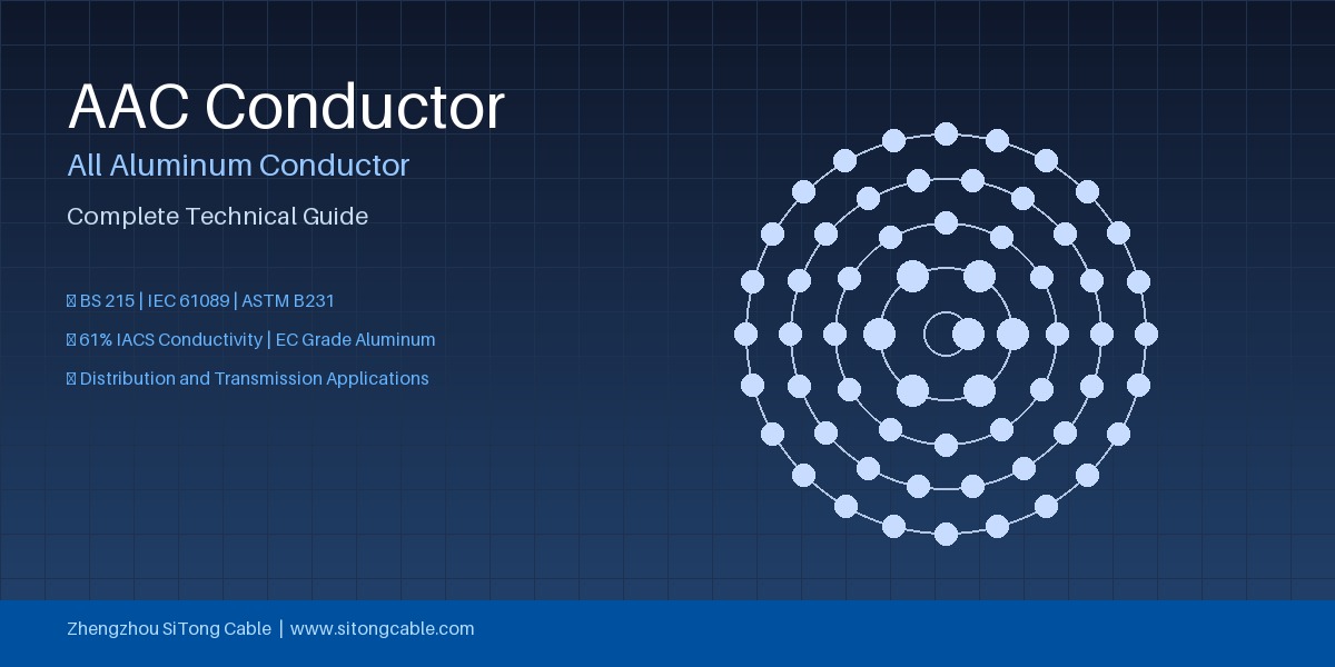
- Bare Conductor Products
- Medium Voltage Power Cable - Detailed Specs
- Low Voltage Power Cable - Selection Reference
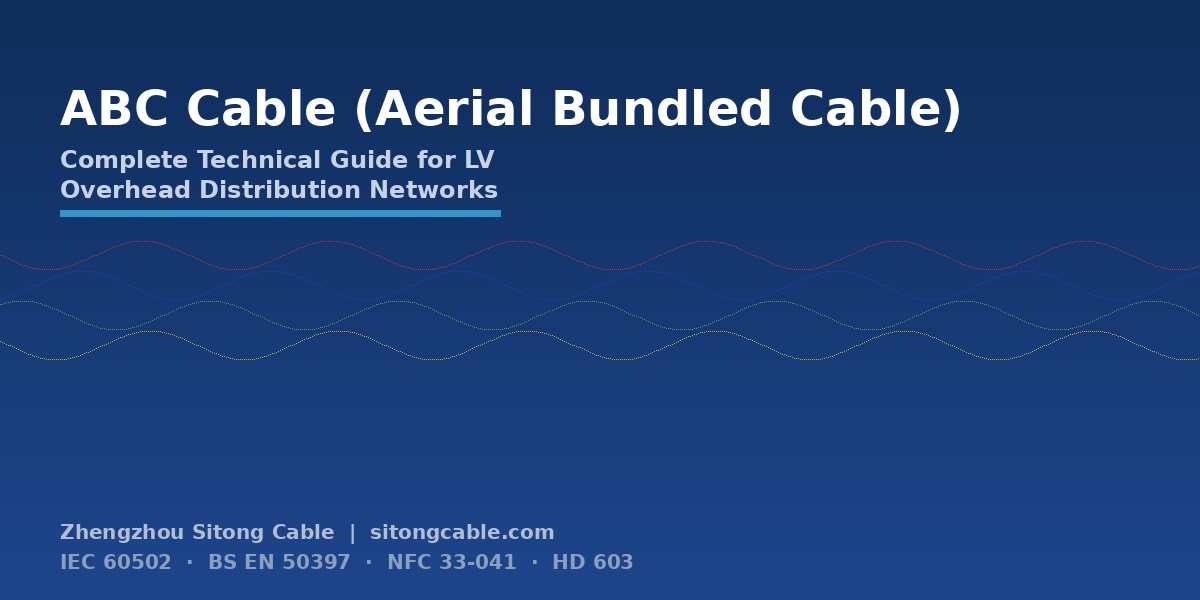
- Aerial Bundled Cable
For technical inquiries or product requirements, contact the SiTong Cable technical team for professional guidance.
This article is for reference purposes only. Technical parameters are subject to the latest IEC/GB standards and product datasheets.