AAC (All Aluminum Conductor) Installation & Maintenance: Complete Field Guide
AAC (All Aluminum Conductor) Installation & Maintenance: Complete Field Guide
1. Introduction
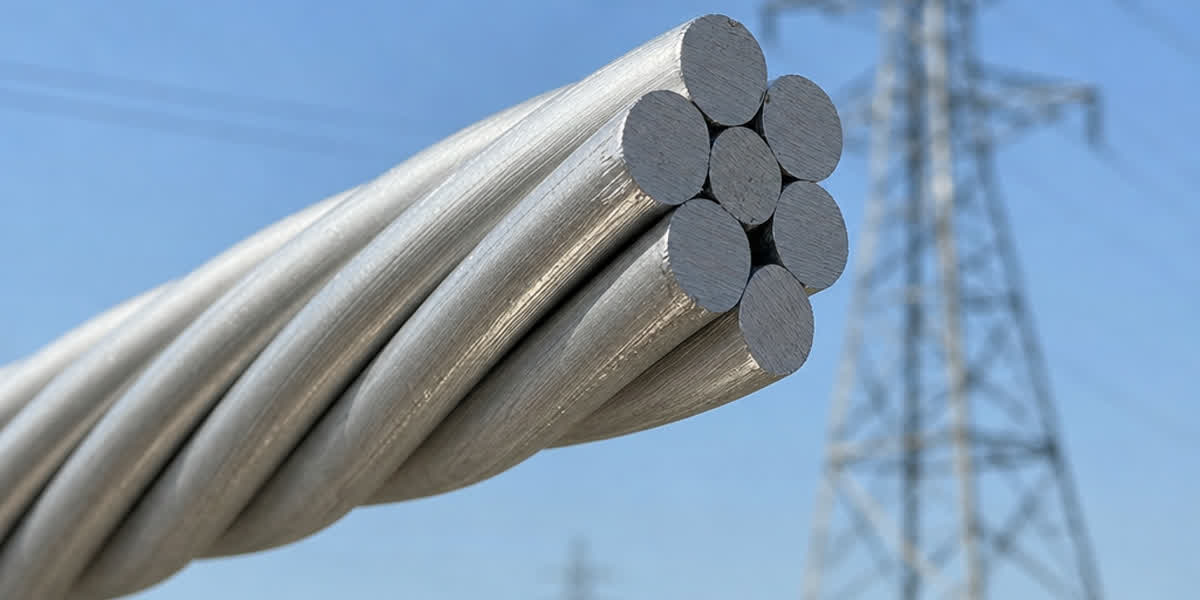
All Aluminum Conductor (AAC) is a stranded conductor made from 1350-H19 or 1350-O grade electrical-grade aluminum alloy wires. With an electrical conductivity of 61% IACS, lightweight construction, and excellent corrosion resistance, AAC is widely used in urban distribution networks, coastal regions, and short-to-medium span transmission lines. Unlike ACSR (Aluminum Conductor Steel Reinforced), AAC contains no steel core — it has a simpler construction, is easier to handle during installation, and is particularly well-suited for applications where corrosion resistance is critical and tension requirements are moderate.
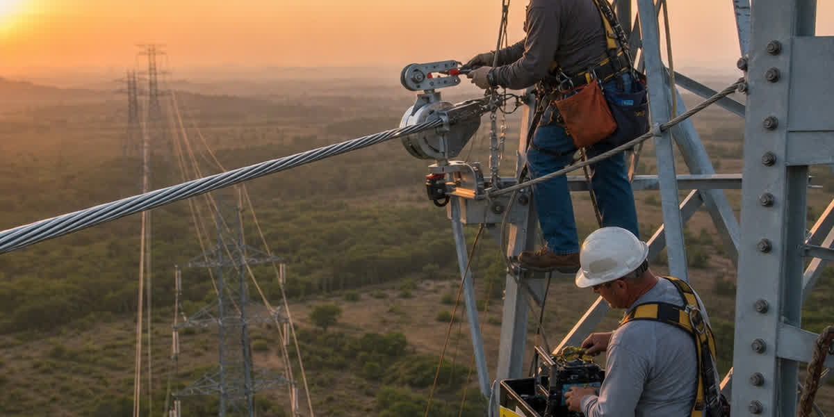
This guide is designed for field engineers, line construction crews, and maintenance teams. It covers preparation, installation procedures, acceptance testing, routine maintenance, and troubleshooting for AAC conductors, helping to maximize service life and operational reliability.
2. Pre-Installation Preparation
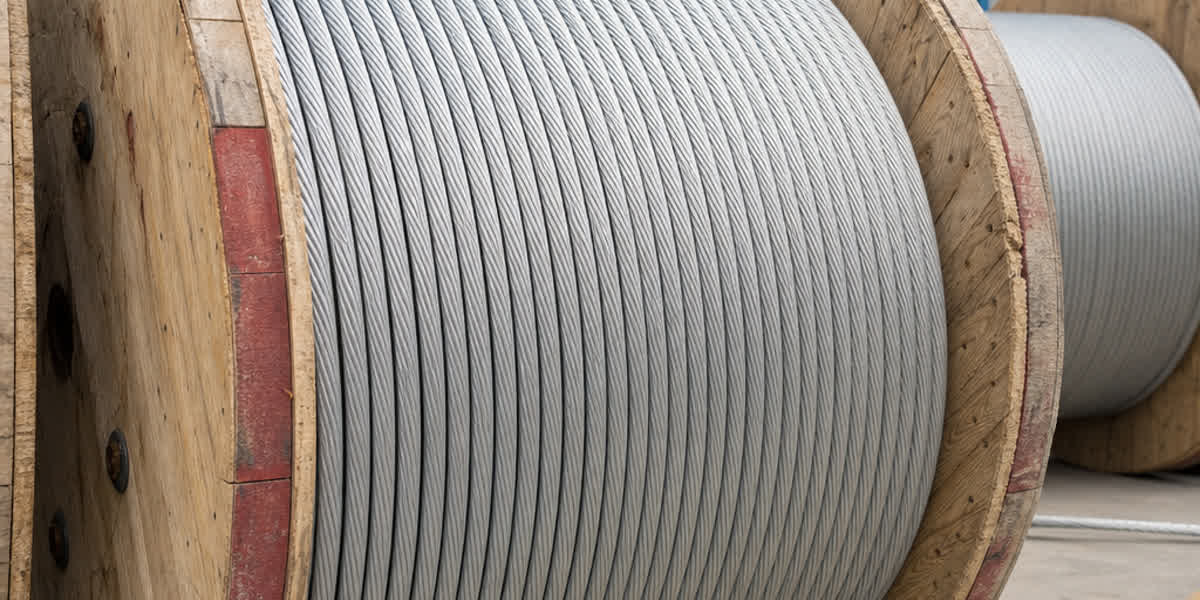
2.1 Receiving and Storage Inspection
| Inspection Item | Acceptance Criteria | Notes |
|---|---|---|
| Visual inspection | No broken strands, corrosion, or mechanical damage | Use magnifying glass for surface micro-cracks |
| Reel integrity | No damage to wooden drum; steel strapping intact | Record reel number and serial number |
| Documentation | Certificate of conformity, tensile test report, resistance test report | Verify against purchase order |
| Length verification | Confirm by resistance method or weigh method | Deviation shall not exceed ±2% |
| Packaging | Outer waterproof wrapping intact | Check interior strands if wrapping is damaged |
⚠️ Important: AAC is softer than ACSR and more susceptible to indentation and abrasion during transport. Inspect every reel upon receipt. Document any damage immediately with photos and notify the supplier.
2.2 Tools and Equipment Checklist
| Tool Category | Required Equipment | Application Notes |
|---|---|---|
| Pulling equipment | Hydraulic puller (constant tension control), winch | Pulling speed shall not exceed 5 m/min (AAC recommendation) |
| Pay-out equipment | Tensioner (stepless speed control), reel stands | Maintain constant pay-out tension to prevent conductor ground drag |
| Stringing sheaves | Nylon-lined sheaves, corner sheaves, grounding sheaves | Sheave diameter ≥ 20× conductor diameter |
| Splicing tools | Hydraulic compression tool (400 kN+), dies (matching conductor size) | Pull-off test required on sample splices |
| Sagging tools | Come-along tensioner, load cell | Sag tension at 90% of design target |
| Safety equipment | Grounding rods, insulated gloves, voltage detector, safety harness | Check expiration dates and insulation integrity before use |
| Measuring instruments | Thermal imager, laser rangefinder, tension dynamometer, multimeter | For parameter verification and acceptance testing |
2.3 Construction Plan Essentials
- Pulling section length: Maximum 2 km per section for AAC. Longer sections increase risk of ground abrasion.
- Crossing protection: Install protective scaffolding or guard nets when crossing roads, railways, or energized lines.
- Pulling direction: Pull from high elevation towards low elevation to minimize conductor-to-sheave friction.
- Weather conditions: Wind ≤ Beaufort scale 5, no precipitation, ambient temperature ≥ -10°C.
3. Engineering Calculations
3.1 Sag-Tension Calculation
AAC sag-tension analysis uses the catenary model or parabolic approximation:
Parabolic formula:
D = (w × S²) / (8 × T)
Where: - D = sag (m) - w = conductor weight per unit length (kg/m) - S = span length (m) - T = horizontal tension (N)
Typical AAC Design Parameters:
| Parameter | Recommended Value | Notes |
|---|---|---|
| Maximum working tension | 20% RTS (Rated Tensile Strength) | AAC is creep-sensitive; avoid higher tensions |
| Initial stringing tension | 15% RTS | Accounts for long-term creep sag |
| Safety factor | ≥ 3.0 (conductor) | Per IEC 60826 |
| Temperature range | -20°C to +80°C (normal operation) | AAC max continuous operating temperature 90°C |
3.2 Creep Characteristics
AAC has no steel core, so aluminum creep effects are more pronounced than in ACSR. Creep causes permanent elongation and increased sag.
| Creep Stage | Time Range | Creep Strain (% of initial length) | Influencing Factors |
|---|---|---|---|
| Primary creep | 0-50 hours | 0.02%-0.05% | Tension level, temperature |
| Secondary creep | 50-5,000 hours | 0.05%-0.15% | Time, temperature (Arrhenius law) |
| Tertiary (stable) | > 5,000 hours | Stabilizes | Very slow continued growth |
💡 Design Tip: Use a "creep compensation pre-stretch" technique — pull AAC at 30% RTS for 30-60 minutes before final sagging to remove most primary creep. Set initial sag at 95% of the final creep sag target.
3.3 Thermal Expansion Effects
AAC has a linear expansion coefficient of 23.0 × 10⁻⁶ /°C (compared to 18.9 × 10⁻⁶ /°C for ACSR), making temperature effects more significant:
ΔD = (α × ΔT × S²) / (8 × T)
Where α is the expansion coefficient and ΔT is the temperature difference.
Sag vs. Temperature (AAC 400 mm², 200 m span):
| Temperature | Sag (m) | Change from 20°C |
|---|---|---|
| -10°C | 1.85 | -0.45 m |
| 20°C | 2.30 | Baseline |
| 40°C | 2.58 | +0.28 m |
| 60°C | 2.89 | +0.59 m |
3.4 Current-Carrying Capacity
AAC ampacity is calculated per IEEE 738 / IEC 61597:
I = √[(q_c + q_r - q_s) / R(T)]
Where q_c is convective heat loss, q_r is radiative heat loss, q_s is solar heat gain, and R(T) is AC resistance at operating temperature.
⚠️ Key Difference: At the same cross-section, AAC carries 5%-10% more current than ACSR because there is no steel core causing hysteresis and eddy current losses. However, AAC's lower working tension limit (20% RTS vs. 25%-30% for ACSR) requires additional sag verification at high load.
4. Installation Procedure
4.1 Conductor Stringing
| Step | Operation | Technical Requirements |
|---|---|---|
| 1 | Position reel stands | Pay-out aligned with pulling direction; connect tail-end grounding |
| 2 | Initial pull | Use nylon pilot line with swivel to connect to conductor |
| 3 | Tension stringing | Maintain tension at 2%-5% of nominal — prevent ground drag |
| 4 | Sheave monitoring | Station personnel at corner sheaves to prevent conductor jumping |
| 5 | Pull to tower | Mark position, temporary anchor, maintain tension |
| 6 | Sag observation | Using theodolite or laser rangefinder |
⚠️ Safety: AAC has low torsional stiffness. Always use a swivel during stringing to prevent kinking. Once a kink forms, the affected section must be cut out and re-spliced.
4.2 Sagging Operation
| Step | Operation | Technical Requirements |
|---|---|---|
| 1 | Dead-end preparation | Install dead-end clamp at terminal tower; pre-tension to 10% of design |
| 2 | Sag the line | Progress from one end, in 2-3 passes |
| 3 | Tension adjustment | Monitor with load cell; adjust to ±3% of design value |
| 4 | Sag fine-tuning | Adjust for observed temperature using sag-temperature reference table |
| 5 | Install dead-end clamp | Install and compress at opposite end |
| 6 | Anchor | Secure both ends; install vibration dampers |
Typical AAC Sag Control (400 mm², wind zone 3):
| Condition | Temperature | Control Tension (kN) | Sag (m) |
|---|---|---|---|
| Initial stringing | 20°C | 8.5 (15% RTS) | 2.30 |
| Post-creep check | - | 8.0 | 2.45 |
| Max loading | -5°C + ice | 11.3 (20% RTS) | 1.85 |
| High temperature | 80°C | 6.1 | 3.20 |
4.3 Conductor Compression
AAC splicing and dead-ending shall use hydraulic compression only. Explosive or mechanical crimping is not permitted.
| Joint Type | Location | Die Requirements | Compressions | Acceptance Criteria |
|---|---|---|---|---|
| Dead-end (tension) | Terminal and angle towers | Hexagonal or octagonal dies | ≥ 3 per tube | ≥ 95% conductor RTS |
| Full-tension splice (mid-span) | In-span joints | Hexagonal dies | ≥ 5 per tube | ≥ 95% conductor RTS |
| Jumper (non-tension) | Tension tower jumpers | Match conductor diameter | 2 per tube | Reliable connection, low contact resistance |
💡 AAC Compression Tips: AAC aluminum strands are softer than ACSR steel/aluminum strands. Dies must be precision-matched — clearance ≤ 0.5 mm. Measure across-flats after compression; deviation shall not exceed ±0.2 mm.
4.4 Vibration Mitigation
| Measure | Application | Installation Spacing | Quantity |
|---|---|---|---|
| Stockbridge damper | Standard spans (200-500 m) | 0.5-1.5 m from dead-end | 1-2 per end |
| Spacer damper | Long spans or twin-bundle | Per design layout | Every 50-80 m |
| Armor rods | All spans | Cover 150-300 mm from clamp exit | 1 set per end |
| Preformed helical rods | Short-to-medium spans | 100-200 mm from clamp exit | 1 set per end |
⚠️ AAC-Specific Note: AAC has better self-damping than ACSR (no steel core — higher internal friction), but vibration dampers are still required in aeolian vibration zones (2-8 m/s wind). Use the "energy balance method" for damper design to ensure system absorption exceeds wind energy input.
4.5 Grounding and Connections
| Component | Requirement | Standard |
|---|---|---|
| Ground wire | ≥ 70 mm² copper stranded | IEEE 837 |
| Ground resistance | ≤ 10 Ω per tower | IEC 62305 |
| Jumper connections | Parallel-groove or H-type clamps | Contact resistance ≤ 1.2× equivalent conductor length |
| Conductor-to-hardware | Steel hardware must be hot-dip galvanized (≥ 86 μm) | ASTM A123 |
5. Post-Installation Inspection & Testing
| Inspection Item | Method | Acceptance Criteria |
|---|---|---|
| Sag | Theodolite or laser rangefinder | Deviation ≤ ±5% of design |
| Tension | Load cell measurement | Deviation ≤ ±3% of design |
| Conductor surface | Full-length visual inspection | No broken strands; no indentations > 0.5 mm deep |
| Compressed fittings | Across-flats measurement + X-ray spot check | Across-flats deviation ≤ 0.2 mm; ≥ 95% compression |
| Contact resistance | Micro-ohmmeter at jumper and splice tubes | ≤ 1.2× equivalent conductor resistance |
| Clearance | Tape measure or laser | ≥ Minimum design electrical clearance |
| Vibration countermeasures | Visual + grip test | Firmly installed; slippage ≤ 2 mm |
| Corona test | UV camera (night or overcast) | No visible corona discharge points |
6. Routine Maintenance Schedule
| Frequency | Maintenance Activity | Details |
|---|---|---|
| Monthly | Infrared thermal imaging | Scan splices, dead-ends, jumpers — temperature rise ≤ 10°C above ambient |
| Quarterly | Sag measurement | Measure representative spans, record trend |
| Semi-annual | Vibration damper inspection | Check for displacement, wear, detachment; adjust if slippage > 10 mm |
| Annual | Full patrol | On-foot or drone inspection for corrosion, broken strands, foreign objects |
| Every 3 years | Sample tensile test | Take 1 m samples from each end; lab tensile and torsion test |
| Every 5 years | Electrical parameter review | Measure DC resistance, reactance, capacitance — compare to design |
| Every 10 years | Major refurbishment assessment | Evaluate remaining service life based on historical data; determine re-conductoring needs |
📊 Trend Analysis: Year-over-year sag increase is the most sensitive degradation indicator for AAC lines. Build a "sag vs. time" database. A sag increase exceeding 3% in a single year warrants investigation. Track maximum thermal hotspot temperature over time to identify accelerating degradation patterns.
7. Troubleshooting Common Issues
| Problem | Likely Cause | Solution |
|---|---|---|
| Excessive sag | Creep not fully compensated; initial tension too low; overload operation | Re-sag the line; verify design tension; limit loading |
| Hot splice/connector | Poor compression; surface oxidation | Re-grind and re-crimp; replace clamp; apply conductive grease |
| Aeolian vibration / broken strands | Missing or failed vibration dampers | Install appropriate dampers; replace damaged strands |
| Conductor kinking | No swivel used during stringing | Cut out kinked section; re-pull with swivel |
| Pitting corrosion | Coastal/industrial environment; damaged protective coating | Apply corrosion-inhibiting grease; shorten inspection intervals |
| Corona discharge | Surface burrs or debris; high altitude / high field strength | Smooth surface; install grading rings |
| Ice overload | Insufficient ice-load design margin | Add de-icing measures (current melting); enhance monitoring |
| Fatigue at hardware exit | Cumulative aeolian vibration damage | Check damping system; add armor rods |
8. Safety Considerations
| Hazard | Precaution |
|---|---|
| Induced voltage | Install grounding at both ends of the work zone; use personal protective grounds |
| Uncontrolled pulling tension | Puller and tensioner must have overload protection; maintain communication |
| Falls from height | Use dual-lanyard safety harness on towers; establish safety zone below |
| Compression tool operation | Operator must be trained; keep hands away from die closure area |
| Conductor break during sagging | Keep personnel clear of sag zone; use tension limiters |
| Severe weather | No elevated or stringing work when wind > Beaufort scale 8 or during thunderstorms |
| Proximity to energized lines | Maintain minimum approach distance (10 kV ≥ 1.5 m; 110 kV ≥ 3.0 m) |
9. FAQ
Q1: What are the main differences between AAC and ACSR during installation? AAC is softer, more creep-prone, and requires more precise compression dies. Stringing tension should be limited to 20% RTS (vs. 25%-30% for ACSR). A swivel is mandatory during stringing to prevent kinking. Maintenance should focus on sag trends and creep behavior.
Q2: What is the maximum operating temperature for AAC? Per ASTM B230 / IEC 61089, standard operating temperature is 75°C-90°C (depending on temper H19 or O). Emergency loading (contingency) up to 100°C-120°C is permissible for no more than 1 hour.
Q3: What is the maximum span length for AAC? Depends on cross-section and weather zone. Typical ranges: AAC 50 mm²: 80-120 m; AAC 200 mm²: 150-250 m; AAC 500 mm²: 200-350 m. Beyond these ranges, consider AAAC, ACAR, or ACSR.
Q4: When should AAC be replaced? Replace when: tensile strength drops below 80% of original RTS; remaining cross-section from corrosion is less than 75%; broken strands exceed 5% of total; annual sag increase exceeds 3% for three consecutive years; compression fitting temperature rise exceeds 15°C on two consecutive thermal scans.
Q5: What corrosion protection measures are recommended for coastal AAC installations? AAC has better inherent corrosion resistance than copper or steel-cored conductors. For extreme coastal environments (< 5 km from shoreline), consider: using 1350-O annealed temper (more corrosion-resistant than H19); including annual corrosion inspection in the maintenance plan; using stainless steel hardware; applying vapor-phase corrosion inhibitor where practical.
Q6: Should AAC be pre-loaded after installation to reduce creep? Highly recommended. After sagging, apply 30% RTS tension for 30-60 minutes to remove over 80% of primary creep. Re-check sag after pre-stretch and adjust as needed.
Q7: What are the construction differences between AAC and AAAC? AAAC (All Aluminum Alloy Conductor) is 25%-30% stronger than AAC with lower creep, allowing working tensions up to 25%-30% RTS. However, AAAC requires higher compression pressure due to harder alloy. Sag control parameters differ — verify the conductor type before selecting construction parameters.
Q8: What is the shelf life of AAC conductor? Stored in dry, ventilated conditions in original packaging, AAC has a shelf life of approximately 2 years. Beyond 2 years, perform sample tensile and resistance testing before installation. Avoid storage near corrosive chemicals (acids, alkalis, chlorides).
For detailed AAC product specifications and pricing, visit our AAC product page or contact our sales team.
10. Standards Reference
| Standard | Title | Scope |
|---|---|---|
| ASTM B230 | Aluminum 1350-H19 Wire for Electrical Purposes | AAC strand material |
| IEC 61089 | Round wire concentric lay overhead electrical stranded conductors | Overhead conductor general specification |
| IEEE 738 | Calculating Current-Temperature Relationship of Bare Overhead Conductors | Ampacity calculation |
| IEC 61597 | Overhead electrical conductors — Calculation methods for stranded bare conductors | Current-carrying and loss calculation |
| IEC 60826 | Design criteria of overhead transmission lines | Line design criteria |
| IEEE 524 | Guide for the Installation of Overhead Transmission Line Conductors | Stringing and installation |
| ASTM B231 | Concentric-Lay-Stranded Aluminum 1350 Conductors | AAC stranding construction |
| CIGRE TB 111 | Guide for Installation of Transmission Line Conductors | International installation guidance |
| IEC 61284 | Overhead lines — Requirements and tests for fittings | Hardware requirements |
| DL/T 5285 | Technical Specification for Conductor Crimping of Overhead Transmission Lines | Chinese industry standard |
11. About SiTong Cable
This guide was prepared by the SiTong Cable engineering team. With over 15 years of manufacturing experience, we produce overhead conductors in strict compliance with ASTM, IEC, BS, and other international standards. For AAC conductor procurement or technical inquiries:
- 🌐 Browse our AAC product range
- 📧 Email: sales@sitongcable.com
- 📞 Phone: +86-371-69176007
- 🏭 Factory: Gongyi City, Henan Province, China
All technical data in this guide references the international standards listed above. Final engineering design should be performed by qualified professionals based on site-specific conditions.