Cable Solar (Cable Fotovoltaico / Cable PV) — Guía Técnica Completa: Estándares, Especificaciones y Selección para Sistemas de Energía Solar
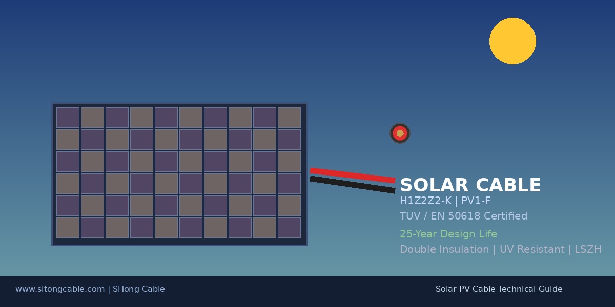
Cable Solar (Cable Fotovoltaico / Cable PV) — Guía Técnica Completa: Estándares, Especificaciones y Selección para Sistemas de Energía Solar
Los cables solares fotovoltaicos (PV) son cables especializados diseñados para la transmisión de energía DC en sistemas de generación de energía solar. A diferencia de los cables de alimentación convencionales, los cables solares deben soportar condiciones ambientales extremas — exposición continua a rayos UV, temperaturas altas desde +90°C hasta -40°C, humedad, ozono y estrés mecánico — durante una vida útil de más de 25 años. Con las instalaciones fotovoltaicas globales superando los 2 TW de capacidad acumulada (IEA PVPS 2026), seleccionar el cable solar adecuado se ha convertido en una decisión de ingeniería crítica para la confiabilidad y seguridad del sistema. Esta guía proporciona una visión técnica completa de los tipos de cables solares, estándares internacionales (TÜV 2PfG/EN 50618, IEC 62930, UL 4703), materiales de construcción, metodología de dimensionamiento y mejores prácticas para sistemas fotovoltaicos residenciales, comerciales y de gran escala.
1. ¿Qué es un Cable Solar? — Descripción General y Características Clave
1.1 Definición y Función
Los cables solares (también llamados cables PV o cables fotovoltaicos) son cables unipolares con aislamiento reticulado diseñados específicamente para sistemas de energía fotovoltaica. Conectan paneles solares (módulos), inversores, cajas de combinación, controladores de carga y baterías en circuitos DC.
1.2 Requisitos Clave de Rendimiento
| Requisito | Especificación | Importancia |
|---|---|---|
| Tensión Nominal | DC 1.5 kV / 1.8 kV | Alto voltaje reduce corriente y pérdidas de cobre |
| Rango de Temperatura | -40°C a +90°C (continuo), +120°C (cortocircuito) | Paneles en tejados superan 70°C en verano |
| Resistencia UV | Clase A (ISO 4892-2) — 720+ horas arco xenón | Exposición solar continua degrada PVC estándar |
| Resistencia al Ozono | IEC 60811-403 | Ozono de inversores y contaminantes exteriores |
| Retardante de Llama | IEC 60332-1-2 | Seguridad contra incendios |
| Resistencia Mecánica | ≥ 1200 N (6 mm²) | Estrés por viento, nieve y ciclos térmicos |
| Vida Útil | 25+ años vs. 5-10 años (cable PVC estándar) | Coincide con garantía de módulos PV |
1.3 Cable Solar vs. Cable de Alimentación Estándar
| Propiedad | Cable Solar (PV) | Cable de Alimentación PVC |
|---|---|---|
| Material de Aislamiento | XLPO / EPR | PVC |
| Temperatura | -40°C a +120°C | -15°C a +70°C |
| Resistencia UV | Excelente | Pobre |
| Libre de Halógenos | Sí (LSZH) | Contiene halógenos |
| Tensión Nominal | DC 1.5/1.8 kV | AC 0.6/1 kV |
| Doble Aislamiento | Sí | Generalmente simple |
| Vida Útil | 25+ años | 3-5 años |
2. Estándares Internacionales para Cables Solares
2.1 Estándares Europeos / Internacionales
Los dos estándares dominantes para cables solares a nivel mundial son EN 50618 (estándar europeo) e IEC 62930 (estándar de la Comisión Electrotécnica Internacional).
| Estándar | Título | Requisitos Clave | Marcado Típico |
|---|---|---|---|
| EN 50618:2014 | Cables eléctricos para sistemas fotovoltaicos | DC 1.5 kV, -40°C a +90°C, XLPO, libre de halógenos | H1Z2Z2-K |
| IEC 62930:2017 | Cables para sistemas PV hasta DC 1.5 kV | Basado en EN 50618, alcance global | PV1-F o H1Z2Z2-K |
| TÜV 2PfG 1169/08.2007 | Requisitos para cables en sistemas fotovoltaicos | Estándar alemán original, DC 1.8 kV | PV1-F (certificado TÜV) |
2.2 Estándares Norteamericanos
| Estándar | Título | Requisitos Clave |
|---|---|---|
| UL 4703 | Esquema de Investigación para Cable Fotovoltaico | DC 600V a 2000V, clasificación seca/húmeda |
| NEC Artículo 690 | Sistemas Fotovoltaicos Solares | Ampacidad, conductos, dimensionamiento |
2.3 Comparación de Estándares
| Parámetro | TÜV 2PfG 1169 (PV1-F) | EN 50618 (H1Z2Z2-K) | UL 4703 |
|---|---|---|---|
| Máx. Tensión DC | 1.8 kV | 1.5 kV | 600V-2000V |
| Temperatura | -40°C a +90°C | -40°C a +90°C | -40°C a +90°C |
| Aislamiento | XLPO / EPR | XLPO / EPR | XLPE / EPR |
| Libre de Halógenos | Sí | Sí | Sí (LSZH) |
| Mercado | Europa, Asia, Oriente Medio, África | Europa (estándar actualizado) | Norteamérica |
3. Construcción y Materiales del Cable Solar
3.1 Materiales del Conductor
| Material | Propiedad | Aplicación |
|---|---|---|
| Cobre Estañado (Clase 5) | Mejor conductividad (≥58.5 MS/m), excelente resistencia a la corrosión | Estándar para la mayoría de sistemas PV |
| Cobre Desnudo (Clase 2) | Menor costo, pero susceptible a oxidación | Solo aplicaciones interiores |
| Aluminio | Más ligero, menor costo, requiere mayor sección | Sistemas de gran escala |
3.2 Aislamiento y Cubierta
Los cables solares modernos utilizan doble capa de aislamiento:
Capa Interna (Aislamiento): - XLPO: Reticulado por haz de electrones o proceso silano - EPR: Usado en aplicaciones de alta flexibilidad
Capa Externa (Cubierta): - LSZH: Produce mínimo humo y sin gases tóxicos en caso de incendio - XLPO estabilizado UV: Negro con aditivo de carbón para protección UV
3.3 Secciones Transversales Estándar
| Sección (mm²) | AWG Equivalente | Corriente Máx Continua (A) | Aplicación Típica |
|---|---|---|---|
| 1.5 mm² | AWG 15-16 | 15 A | Conexiones cortas de módulos |
| 2.5 mm² | AWG 13-14 | 21 A | Conexiones de cadenas residenciales |
| 4 mm² | AWG 11-12 | 34 A | Residencial/comercial estándar |
| 6 mm² | AWG 9-10 | 44 A | Más común — comercial |
| 10 mm² | AWG 7-8 | 58 A | Cadenas comerciales grandes |
| 16 mm² | AWG 5-6 | 78 A | Alimentadores de caja combinadora |
| 35 mm² | AWG 2 | 125 A | Alimentadores DC principales |
| 50 mm² | AWG 1/0 | 150 A | Líneas troncales DC gran escala |
4. Guía de Dimensionamiento y Selección
4.1 Cálculo de Caída de Tensión
Caída de tensión máxima recomendada: - Lado DC: ≤ 1-3% (matriz al inversor) - Lado AC: ≤ 1-2% (inversor a la red)
Fórmula de caída de tensión DC: Vdrop = 2 × L × I × ρ / A
4.2 Lista de Verificación de Selección
- [ ] Tensión nominal: ≥ 1.5 kV DC (EN 50618)
- [ ] Capacidad de corriente: Isc cadena × 1.25 ≤ ampacidad del cable
- [x] Rango de temperatura: -40°C a +90°C continuo
- [x] Resistencia UV: Ensayado según ISO 4892-2 (720h mínimo)
- [ ] Retardante de llama: IEC 60332-1-2
- [x] Libre de halógenos: LSZH según EN 50618
- [x] Flexibilidad: Conductor Clase 5 de hilos finos
- [x] Certificación: H1Z2Z2-K, PV1-F o UL 4703
5. Tipos de Cables Solares por Aplicación
5.1 Cables de Interconexión de Módulos PV (Latiguillos)
- Cables cortos (0.9m-2.5m) preinstalados en módulos PV
- Típicamente 4 mm² o 6 mm² con conectores MC4
- Color: Rojo (+) y Negro (-) para identificación de polaridad
5.2 Cables de Cadena a Caja Combinadora
- Entre cadenas de módulos PV y cajas combinadoras centrales
- Sección: 6 mm² a 16 mm²
5.3 Alimentadores DC Principales (Caja Combinadora a Inversor)
- Cables DC de alta corriente
- Sección: 25 mm² a 50 mm² o más
5.4 Cables AC (Inversor a Red)
- Cables de alimentación AC estándar (0.6/1 kV)
- SiTong Cable ofrece opciones en su categoría de cables de alimentación
6. Mejores Prácticas de Instalación
6.1 Radio de Curvatura
| Condición de Instalación | Radio Mínimo |
|---|---|
| Instalación fija (unipolar) | 4× diámetro exterior del cable |
| Instalación dinámica | 6× diámetro exterior |
| Instalación en frío (<0°C) | 10× diámetro exterior |
6.2 Enrutamiento del Cable
- Evitar bordes afilados
- Separación AC/DC ≥ 300 mm
- Bucles de goteo en puntos de entrada
6.3 Conexión a Paneles Solares
- Usar solo conectores certificados PV (MC4, Amphenol H4)
- Verificar mecanismo de bloqueo
7. Guía de Productos de Cable Solar en SiTong Cable
SiTong Cable ofrece una gama completa de cables solares para proyectos PV internacionales:
Productos Recomendados
| Producto | Estándar | Tensión | Secciones | Aplicación |
|---|---|---|---|---|
| Cable Solar (PV1-F/H1Z2Z2-K) | TÜV/EN 50618 | DC 1.5 kV | 1.5-35 mm² | Cadenas de módulos, alimentadores |
| Cable de Alimentación AC | IEC 60502 | AC 0.6/1 kV | 1.5-240 mm² | Salida AC del inversor a red |
| Cable de Control | IEC 60227 | AC 0.6/1 kV | 0.5-6 mm² | SCADA, monitoreo, sensores |
Enlaces Internos
Explore las categorías de productos relacionadas: - Productos de Cable Solar — Cables PV certificados TÜV/EN - Productos de Cable de Alimentación — Cables AC para conexión inversor-red
Todos los cables solares SiTong se fabrican con conductores de cobre estañado Clase 5 y aislamiento LSZH reticulado, totalmente conformes con EN 50618 (H1Z2Z2-K) y TÜV 2PfG 1169 (PV1-F), con una vida útil de diseño de 25 años.
FAQ
P1: ¿Puedo usar cable PVC estándar para conexiones de paneles solares?
No. Los cables PVC estándar no son resistentes a los rayos UV y se agrietarán en 1-2 años de exposición exterior. Tampoco tienen la clasificación de flexibilidad en frío a -40°C. Use siempre cable solar certificado TÜV/EN (PV1-F o H1Z2Z2-K).
P2: ¿Cuál es la diferencia entre cables PV1-F y H1Z2Z2-K?
H1Z2Z2-K es el estándar más nuevo (EN 50618:2014), que reemplaza a PV1-F (TÜV 2PfG 1169). H1Z2Z2-K también cubre la clasificación de tensión AC (0.6/1 kV) además de DC 1.5 kV. Ambos son ampliamente aceptados, pero H1Z2Z2-K es la opción preferida para nuevas instalaciones.
P3: ¿Qué tamaño de cable necesito para mi sistema solar residencial?
Para un sistema residencial típico de 5-10 kW, el cable solar 4 mm² o 6 mm² es estándar. El tamaño exacto depende de la corriente de la cadena y la longitud del cable.
P4: ¿Por qué los cables solares son rojos y negros?
La codificación de colores Rojo (+) y Negro (-) ayuda a identificar la polaridad DC durante la instalación y el mantenimiento. EN 50618 requiere esta codificación para todos los cables DC PV.
P5: ¿Cuál es la vida útil de un cable solar en comparación con los paneles?
Los cables solares de calidad certificados según EN 50618 o UL 4703 están diseñados para una vida útil de más de 25 años, coincidiendo con las garantías estándar de los módulos PV.
SiTong Cable fabrica y suministra cables solares certificados TÜV/EN para proyectos PV globales. Contáctenos para especificaciones técnicas, muestras gratuitas y precios al por mayor.