OPGW Cable: Dual-Function Backbone for Smart Power Grids

OPGW Cable: Dual-Function Backbone for Smart Power Grids
1. Introduction: Beyond Traditional Grounding
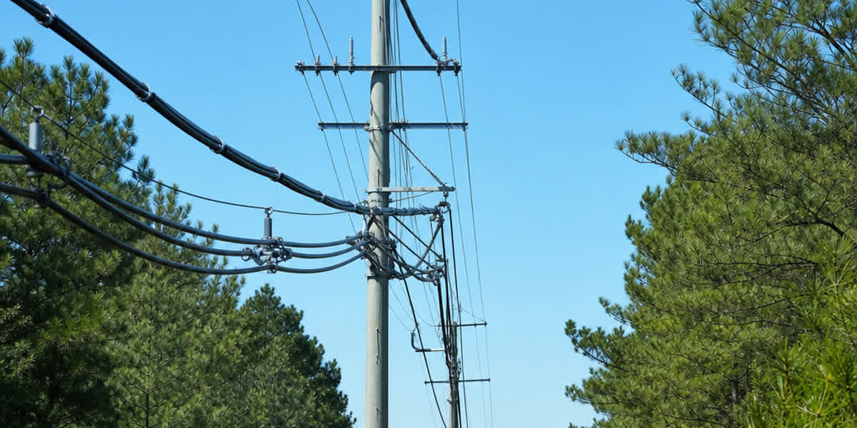
In the era of smart grids and global energy transition goals, overhead transmission lines have evolved far beyond their original role. They are no longer simply conduits for bulk power — they must also serve as the communication backbone for real-time monitoring, teleprotection, SCADA and broadband data transmission. The Optical Ground Wire (OPGW) sits at the heart of this evolution. By replacing a traditional shield wire with OPGW, utilities gain a high-capacity fiber optic link integrated into a robust lightning protection system — two critical functions delivered in a single cable.
For engineers, project managers and procurement professionals working on transmission line projects, understanding OPGW construction, standards and selection criteria is essential to delivering reliable, future-proof grid infrastructure. This guide covers the design, technical parameters, international standards, selection methodology and installation best practices for OPGW cable.
2. OPGW Applications Across the Modern Grid
OPGW is deployed wherever utilities need both overhead-line protection and communication capacity. Typical applications include:
| Application | Function | Typical Fiber Count |
|---|---|---|
| High-voltage transmission lines (110 kV – 750 kV) | Lightning protection + teleprotection signalling | 12 – 48 |
| Smart grid / substation automation | SCADA, PMU data, real-time grid monitoring | 24 – 96 |
| Renewable energy integration (wind, solar) | Grid-code compliance communication, remote control | 24 – 48 |
| Railway traction power lines | Signalling, train control, CCTV backhaul | 12 – 24 |
| Telecom backbone / utility ISP | Broadband services, DWDM transmission | 48 – 144 |
From coastal 132 kV networks to alpine 400 kV corridors, SiTong Cable supplies OPGW solutions engineered to the exact electrical, mechanical and environmental requirements of each project.
3. Structural Innovation and Design
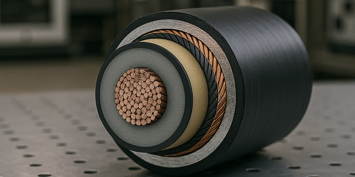
Modern OPGW design centers on protecting delicate optical fibers from the extreme thermal and mechanical stresses of high-voltage environments. The fibers are typically housed within stainless steel or aluminum tubes, buffered by thixotropic gel to prevent moisture ingress and mechanical vibration damage.
Table 1: Comparison of OPGW Core Tube Materials
| Feature | Stainless Steel Tube (SST) | Aluminum-Clad SST | Central Aluminum Tube |
|---|---|---|---|
| Fiber Density | High (up to 144 fibers) | Moderate | Moderate |
| Corrosion Resistance | Excellent | Superior | Good |
| Mechanical Strength | Highest | High | Moderate |
| Thermal Protection | Excellent | Best Heat Dissipation | Moderate |
| Ideal Application | High Fiber Count / Long Span | Extreme Environments | Standard Utility Lines |
The choice of tube design affects not only fiber protection but also the cable's overall diameter, weight and sag performance — all of which influence tower loading and route economics.
4. International Standards and Technical Specifications
Compliance with international standards is non-negotiable for grid reliability. OPGW must balance its electrical conductivity (to handle fault currents) with its tensile strength (to withstand wind and ice loading).
Table 2: Key OPGW Standards
| Standard | Scope |
|---|---|
| IEC 60794-4-10 | OPGW — optical, mechanical and electrical performance requirements |
| IEEE 1138 | OPGW used on electric utility power lines (design, testing, installation) |
| ITU-T G.652 / G.655 | Single-mode fiber characteristics |
| GB/T 7429 / DL/T 832 | Chinese OPGW standards for domestic projects |
Table 3: Typical Technical Specifications for SiTong OPGW Series
| Parameter | 24-Fiber OPGW (Standard) | 48-Fiber OPGW (High Capacity) | 96-Fiber OPGW (Backbone) |
|---|---|---|---|
| Fiber Type | G.652D / G.655 | G.652D / G.657A1 | G.652D |
| Outer Diameter (mm) | 11.4 - 15.0 | 14.5 - 18.2 | 18.0 - 22.5 |
| Rated Tensile Strength (kN) | 45 - 85 | 70 - 120 | 110 - 180 |
| Short Circuit Current (kA²s) | 25 - 65 | 55 - 110 | 100 - 200 |
| DC Resistance (Ω/km) | < 0.65 | < 0.45 | < 0.35 |
| Operating Temp Range | -40°C to +80°C | -40°C to +80°C | -50°C to +85°C |
5. OPGW Selection Criteria for Global Grid Infrastructure
Choosing the right OPGW configuration requires a site-specific approach. Coastal installations require higher aluminum-to-steel ratios to combat salt-air corrosion, while high-altitude lines prioritize a low weight-to-strength ratio to minimize tower loading.
Table 4: GEO-Specific OPGW Configuration Guide
| Region / Climate | Recommended Tube Type | Armour Wire Material | Primary Design Focus |
|---|---|---|---|
| Tropical/Coastal | Aluminum-Clad SST | Al-Clad Steel (ACS) | Corrosion Resistance |
| Alpine / Arctic | Stainless Steel Tube | High-Strength Galvanized | Ice Loading & Tensile |
| Arid / Desert | Central Aluminum Tube | Aluminum Alloy (AA) | Thermal Dissipation |
| Industrial / Urban | Aluminum-Clad SST | ACS + AA Mix | Conductivity & Reliability |
A practical selection workflow:
- Define the communication requirement — determine the fiber count and fiber type (G.652D suits most projects; G.655 is preferred for DWDM backbone links).
- Verify the electrical duty — the short-circuit current capacity (kA²s) must exceed the worst-case fault level at the installation point.
- Check mechanical limits — rated tensile strength (RTS) must cover the maximum sagging tension with the required safety factor for the span and the local ice/wind zone.
- Match the environment — select the tube and armour materials according to the climate (Table 4).
- Confirm with a design review — compare sag-tension curves, vibration damping and hardware compatibility before tender. SiTong Cable engineers can review your tower data and propose the optimal configuration — browse the OPGW range or contact us for a design consultation.
6. Installation and Maintenance Best Practices
Installation of OPGW requires specialized tension stringing equipment to prevent the "micro-bending" of fibers. Key practices include:
- Use tension stringing with calibrated tensioners and travelers sized to the cable's minimum bending radius
- Respect the recommended maximum pulling tension (typically 15–20% of RTS) and the angle limits at each traveler
- Install the correct hardware — suspension clamps, tension clamps and vibration dampers matched to the span
- Splice fibers with trained crews and OTDR-verified splice losses (typically ≤ 0.05 dB per splice)
Monitoring fiber attenuation over the life of the cable is critical, especially after significant lightning strikes or seismic events. For a step-by-step operational reference, see our OPGW Installation & Maintenance: Complete Field Guide for Power & Communication Networks.
7. OPGW vs. ADSS: Choosing the Right Overhead Optical Cable
| Criterion | OPGW | ADSS |
|---|---|---|
| Installation position | Replaces the shield wire at tower top | Installed below phase conductors |
| Voltage range | All levels, including EHV/UHV | Typically up to 110 kV (live-line constraints) |
| Metallic components | Yes (conductive) | No (all-dielectric) |
| Lightning protection | Built-in | None — a separate shield wire is still required |
| Typical application | New or reconductored transmission lines | Existing lines where shield-wire replacement is impractical |
8. FAQ
Q1: What is the difference between OPGW and ADSS? OPGW combines grounding and communication in one metallic cable installed at the tower top, while ADSS is an all-dielectric cable installed below the phase conductors. OPGW provides integrated lightning protection and suits all voltage levels, whereas ADSS is typically limited to lower-voltage lines.
Q2: How many fibers can an OPGW cable carry? Standard OPGW designs range from 12 to 96 fibers; specialized designs support up to 144 fibers or more. The required fiber count is driven by protection signalling, SCADA and telecom capacity planning.
Q3: What standards apply to OPGW manufacturing? The main international standards are IEC 60794-4-10 and IEEE 1138, with fiber performance defined by ITU-T G.652 / G.655. Projects in China typically also reference GB/T 7429 or DL/T 832.
Q4: Can OPGW be installed on an existing transmission line? Yes — OPGW is often used to replace an existing shield wire during reconductoring or upgrade projects, provided tower loads and clearances are re-verified for the new cable's weight and sag characteristics.
Q5: What is the expected service life of OPGW? OPGW is designed for a service life of 30+ years, matching the transmission line itself. Regular attenuation monitoring and periodic inspection of hardware maintain performance over the full lifetime.
9. Conclusion: The Foundation of the Smart Grid
The transition to OPGW is a strategic investment in grid intelligence. By providing a secure, EMI-immune and high-bandwidth communication path, OPGW enables the low-latency teleprotection required for modern renewable energy integration. At SiTong Cable, we specialize in custom-engineered OPGW solutions that meet the most rigorous global standards.
👉 Browse our OPGW product range 👉 OPGW Installation & Maintenance: Complete Field Guide for Power & Communication Networks 👉 Contact our team
📬 Sales inquiries: sales@sitongcable.com | 📞 Phone: +86-371-69176007