Cable Tray Sizing, Fill Ratio and Ampacity Derating: Engineering Guide to NEC 392, IEC 61537, and Thermal Grouping
Cable Tray Sizing, Fill Ratio and Ampacity Derating: Engineering Guide to NEC 392, IEC 61537, and Thermal Grouping
Sizing industrial cable tray systems requires balancing mechanical structural limits, code-mandated fill ratios, and severe ampacity derating penalties caused by thermal stacking. When routing high-density circuits across modern industrial processing plants, utility substations, and data centers, electrical engineers must navigate the stringent requirements of NEC Article 392, IEC 61537, and IEC 60364-5-52. A miscalculation can trigger irreversible cable insulation breakdown, localized hot spots, excessive voltage drop, and catastrophic fire hazards.
This comprehensive technical guide provides electrical engineers, EPC contractors, and procurement specialists with actionable mathematical models, standard fill calculation procedures, grouping derating tables, and best practices for separating power, control, and instrumentation circuits.
1. Cable Tray Classifications and Mechanical Selection Criteria
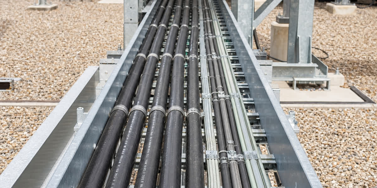
Selecting the proper raceway geometry is the foundational step in cable tray engineering. Under IEC 61537 and NEMA VE 1 / VE 2, cable trays are classified by construction profile, ventilation capacity, and structural load-bearing ratings.
1.1 Structural Types Comparison
| Tray Type | Profile Construction | Heat Dissipation Efficiency | Typical Cable Applications | Contaminant and EMI Protection |
|---|---|---|---|---|
| Ladder Cable Tray | Two longitudinal side rails connected by individual rungs (typically 6", 9", or 12" rung spacing) | Maximum (90% open area; free air convective cooling) | Heavy multi-core and single-core power feeders, armored cables | Minimal; debris passes through; requires covers if outdoor UV or falling debris is an issue |
| Perforated / Ventilated Trough | Formed sheet-metal channel with bottom holes/slots (≥15% open bottom area) | Moderate to High (restricted vertical chimney effect) | Control cables, small power feeders, multi-conductor branch circuits | Moderate; prevents small cables from drooping between rungs |
| Solid-Bottom Cable Tray | Completely enclosed non-ventilated channel | Poor (cables must be derated significantly as in an enclosed raceway) | Sensitive instrumentation circuits, telecommunications, hazardous areas | Maximum; prevents vapor accumulation, EMI ingress, and physical puncture |
| Wire Mesh / Basket Tray | Welded high-tensile wire grid (typically 2" x 4" mesh) | Maximum (convective air flow across all axes) | Data center cabling, low-voltage control circuits, light industrial power | Minimal; vulnerable to external mechanical impacts; rapid installation |
For main distribution substations and heavy industrial facilities, ladder trays are the industry standard for routing our medium and low voltage power cable range due to superior structural strength-to-weight ratios and unobstructed convective cooling.
1.2 Load Classifications and Deflection Limits (NEMA VE 1 vs. IEC 61537)
Under NEMA VE 1, cable trays are designated by a load/span class (such as Class 12C, 20A, 20C). The number represents the support span in feet (e.g., 20 feet = 6.1 m), and the letter indicates the working load capacity: * Class A: 50 lbs/linear foot (74.4 kg/m) * Class B: 75 lbs/linear foot (111.6 kg/m) * Class C: 100 lbs/linear foot (148.8 kg/m)
Under IEC 61537, manufacturers define the Safe Working Load (SWL) tested over standardized support spans with a maximum longitudinal deflection limit of L/100 or L/200, ensuring structural integrity under full thermal load and maintenance personnel live loads (typically a 90 kg concentrated load at mid-span).
2. Fill Ratio Calculations and Code Limitations (NEC 392 vs. IEC 61537)
Cable tray capacity cannot simply be filled to the brim. Excessive fill restricts airflow, traps convective heat, and makes pulling replacement cables nearly impossible.
2.1 Mathematical Formulas for Fill Area
The physical cross-sectional area of any individual insulated cable i is calculated from its overall outer diameter (D_i):
$$A_i = \frac{\pi}{4} D_i^2 \approx 0.7854 \times D_i^2$$
For a cable tray with internal usable width W and internal usable depth H, the gross cross-sectional area is:
$$A_{\text{tray}} = W \times H$$
However, cable outer jackets do not pack with 100% density; interstitial voids exist between circular geometries. In standard practice: * True Cable Volume Fill: $\sum A_i$ * Equivalent Bounding Area Fill: $\sum D_i^2$ (used in several American design conventions)
2.2 NEC 392.22 Fill Requirements for Multiconductor Cables (2000V or Less)
NEC Article 392 differentiates fill requirements based on cable outer diameter and whether conductors are single-core or multiconductor:
- Multiconductor Cables Containing No. 4/0 AWG (107 mm²) or Larger:
- The sum of the diameters of all cables shall not exceed the internal cable tray width (W).
-
Cables must be installed in a single layer with no stacking: $$\sum_{i=1}^{n} D_i \le W$$
-
Multiconductor Cables Smaller than No. 4/0 AWG:
- The total sum of the cross-sectional areas of all cables shall not exceed the maximum allowable cable fill area specified in NEC Table 392.22(A).
-
For ladder or ventilated trough trays with a 6-inch usable depth, the allowable fill area represents an equivalent solid depth of roughly 1.0 to 1.4 inches—meaning maximum physical fill is typically limited to 40% to 50% of total tray cross-section to maintain ventilation.
-
Combination of Large and Small Multiconductor Cables:
- Sizing is governed by the formula: $$\sum D_{\text{large}} + \left(\frac{\sum A_{\text{small}}}{\text{Allowable Unit Area}}\right) \le W$$
2.3 Single-Conductor Cables in Ladder Trays (NEC 392.22(B))
Single-conductor power cables generate strong alternating magnetic fields that induce eddy currents in adjacent metals and mutual heating. NEC mandates: * Single-conductor cables 1000 kcmil (506 mm²) and larger must be installed in a single layer with total diameter not exceeding tray width. * Conductors from 250 kcmil to 900 kcmil must not exceed the fill area in NEC Table 392.22(B)(1), Column 1. * Where routed in three-phase trefoil (triangular) configurations, the total sum of conductor diameters must satisfy width spacing requirements, secured with certified non-magnetic cleats.
3. Thermal Physics and Ampacity Derating Calculations
A cable rated for 400 Amperes in free air cannot carry 400 Amperes when laid alongside 12 other fully loaded cables in a tray. Heat dissipation occurs via radiation and natural convection. When multiple heat sources are clustered, ambient air temperature within the tray bundle rises, reducing the conductor-to-ambient thermal gradient.
3.1 Total Derating Equation
The adjusted continuous allowable ampacity (I_adj) of a cable inside a tray is calculated as:
$$I_{\text{adj}} = I_{\text{base}} \times F_{\text{temp}} \times F_{\text{group}} \times F_{\text{tray}}$$
Where: * I_base = Base continuous ampacity from reference standards (e.g., NEC Table 310.16 / 310.17 or IEC 60364-5-52 Table B.52.12). * F_temp = Ambient temperature correction factor: $$F_{\text{temp}} = \sqrt{\frac{T_{\text{max}} - T_{\text{ambient}}}{T_{\text{max}} - T_{\text{base}}}}$$ (For 90°C XLPE insulation in a 45°C industrial ambient with 30°C base, F_temp = sqrt((90-45)/(90-30)) = sqrt(0.75) ≈ 0.866). * F_group = Grouping reduction factor according to installation arrangement. * F_tray = Tray type configuration factor (e.g., solid-bottom cover penalty).
3.2 IEC 60364-5-52 Table B.52.17 Grouping Factors for Cables in Trays
The International Electrotechnical Commission provides empirically validated grouping reduction factors for single-layer arrangements on perforated or ladder trays:
| Number of Cables / Circuits in Group | Touching (Single Layer) | Maintained Spacing (≥ 1 × D_e) | Two Touching Layers | Multi-Layer Stacked (Uncontrolled) |
|---|---|---|---|---|
| 1 Circuit (3 cores) | 1.00 | 1.00 | 0.80 | 0.70 |
| 2 Circuits | 0.88 | 1.00 | 0.73 | 0.60 |
| 3 Circuits | 0.82 | 0.98 | 0.68 | 0.52 |
| 4 Circuits | 0.79 | 0.96 | 0.65 | 0.46 |
| 6 Circuits | 0.76 | 0.94 | 0.61 | 0.40 |
| 9 Circuits | 0.73 | 0.92 | 0.58 | 0.35 |
| 12+ Circuits | 0.70 | 0.90 | 0.55 | 0.30 |
Key Engineering Takeaway: Placing cables touching in a single layer forces an immediate 20% to 30% reduction in ampacity. If engineers allow haphazard multi-layer stacking, ampacity drops by up to 70%, requiring massive conductor up-sizing. For secondary branch distribution, using certified tray-rated electric wire and building wire with high-temperature 90°C cross-linked insulation preserves ampacity margins under dense configurations.
4. Electromagnetic Separation and Segregation Rules
Routing power cables and low-voltage signal circuits in the same raceway without physical shielding is a primary cause of high-frequency noise, data packet loss, and sensor malfunction.
4.1 Minimum Separation Distances (EN 50174-2 & IEEE 518)
To prevent inductive and capacitive coupling between medium/low voltage power feeders and sensitive instrumentation or communication cables, strict physical separation or metallic barriers must be enforced:
| Circuit Voltage / Power Level | Parallel Run < 35 Meters | Parallel Run 35 to 100 Meters | Parallel Run > 100 Meters |
|---|---|---|---|
| MV Power Feeder (> 1kV) vs. Signal | 450 mm (18 in) or Metallic Divider | 600 mm (24 in) + Divider | 900 mm (36 in) + Separate Tray |
| LV Power Feeder (400V / 480V, > 20A) vs. Signal | 300 mm (12 in) or Metallic Divider | 450 mm (18 in) | 600 mm (24 in) |
| LV Branch Circuits (< 20A) vs. Signal | 150 mm (6 in) or Metallic Divider | 200 mm (8 in) | 300 mm (12 in) |
When spatial constraints prohibit dual tray systems, installing continuous galvanized steel barrier strips within a single tray isolates high di/dt switching noise from precision shielded control cables.
5. Mechanical Restraint, Cleating and Termination Hardware
During three-phase short-circuit conditions, electromagnetic repulsion forces between adjacent conductors reach thousands of Newtons per meter. Unrestrained cables will violently whip, tearing off tray rungs, rupturing outer sheaths, and destroying terminations.
-
Short-Circuit Dynamic Cleating: Single-conductor cables laid in trefoil or flat formation must be secured using certified IEC 61914 cable cleats. Rung ties (nylon zip ties) are only permitted for temporary positioning—they offer zero structural restraint during short circuits. Specify heavy-duty cable fittings and hardware engineered to withstand prospective fault levels (I_sc ≥ 40 kA to 63 kA).
-
Thermal Expansion and Contraction Loops: Copper and aluminum conductors expand linearly with cyclic operating temperatures. On long straight tray runs (> 30 meters), fixed clamps must alternate with guide clamps allowing longitudinal sliding movement, accompanied by 150 mm expansion loops at building expansion joints.
-
Termination Mechanical Relief: Heavy armored cables exiting trays must enter switchgear and transformers via robust support brackets. Conductor tails must terminate in cold-applied or crimped compression cable lugs rated for bidirectional thermal cycling, preventing mechanical cantilever stress on terminal bushings.
6. Step-by-Step Engineering Calculation Example
Design Problem Statement:
An industrial manufacturing plant requires routing four (4) 3-core 400V, 185 mm² copper XLPE/PVC armored power cables and eight (8) 12-core 1.5 mm² shielded control cables across a 45-meter indoor overhead run. * Ambient Temperature: 40°C * Continuous Full Load Current per Power Cable: 310 A * Power Cable Outer Diameter (D_p): 54.2 mm * Control Cable Outer Diameter (D_c): 16.5 mm
Step 1: Minimum Tray Width Determination
To avoid severe multi-layer derating, power cables will be arranged in a single layer with maintained spacing (S = 1.0 × D_p): $$\text{Width}_{\text{power}} = 4 \times D_p + 3 \times S = 4 \times 54.2 + 3 \times 54.2 = 379.4\text{ mm}$$
A solid galvanized divider strip requires 15 mm.
For the eight control cables, routing in two bundled groups of four in a perforated compartment: $$\text{Width}_{\text{control}} = 4 \times 16.5 + 20\text{ mm margin} = 86\text{ mm}$$
$$\text{Total Required Usable Width} = 379.4 + 15 + 86 = 480.4\text{ mm}$$
Standard Tray Selection: Select a standard 600 mm (24 inch) wide ladder tray with 100 mm side rails and 225 mm rung spacing, leaving ample spare capacity for future expansion.
Step 2: Ampacity Verification with Derating
From IEC 60364-5-52 Table B.52.12 (Method E, free air, 3-core XLPE copper): * Base Ampacity at 30°C (I_base) = 448 A
Correction Factors: 1. Temperature correction for 40°C (F_temp): $$F_{\text{temp}} = \sqrt{\frac{90 - 40}{90 - 30}} = \sqrt{\frac{50}{60}} \approx 0.913$$ 2. Grouping correction for 4 cables with maintained spacing (F_group): From Table B.52.17, for 4 cables with S ≥ D, F_group = 0.96 3. Tray factor (F_tray): Open ladder tray = 1.00
Adjusted Permissible Ampacity: $$I_{\text{adj}} = 448\text{ A} \times 0.913 \times 0.96 \times 1.00 = 392.6\text{ A}$$
Since I_adj = 392.6 A > I_load = 310 A, the installation operates well within thermal safety limits with a 26.6% thermal headroom margin.
7. Quality Manufacturing and Engineering Support from SiTong Cable
Achieving code compliance and 30+ year service life requires both rigorous tray engineering and precision-manufactured cables. Zhengzhou SiTong Cable Co., Ltd. (SiTong Cable) is a globally recognized manufacturer specializing in high-performance utility, industrial, and infrastructure cabling.
- Full Tray-Rated Product Line: Our medium and low voltage XLPE power cables, Tray Cable (TC-ER), and instrumentation cables comply fully with IEC 60502-1/2, BS 5467, BS 6724, and UL 1277 flammability requirements (IEEE 1202 / UL 1685 flame testing).
- Advanced Jacket Compounding: Formulated with halogen-free flame-retardant (LSZH), sunlight/UV-resistant, and hydrocarbon/oil-resistant polymers to guarantee zero toxic emissions and robust abrasion resistance during demanding tray pulls.
- Complete System Integration: Beyond bare and insulated conductors, SiTong Cable supplies matched cleats, hardware, and engineering support—from ampacity thermal modeling to custom cut lengths that eliminate field splice joints.
8. Frequently Asked Questions (FAQ)
Q1: Can I install single-conductor and multi-conductor cables in the same cable tray?
Yes, provided that the rules of NEC 392.22 and IEC 61537 are strictly followed. Single-conductor cables must be properly grouped in three-phase sets (A-B-C or trefoil) and securely cleated to prevent inductive heating and short-circuit displacement. If single-conductor cables are 1/0 AWG through 4/0 AWG, they must be installed on ladder trays with maximum rung spacing of 225 mm (9 inches) and sized according to allowable tray cross-sections.
Q2: What is the maximum allowable fill percentage for a ventilated cable tray?
Under NEC Article 392, the maximum permissible fill area for multiconductor control and signal cables smaller than No. 4/0 AWG is typically 40% to 50% of the tray's interior cross-sectional area. Under European IEC practices, fill is often calculated by weight capacity (SWL) and restricted to a single layer for power circuits, or maximum 40% bulk volume for control cables to prevent crushing bottom layers.
Q3: Why is ampacity derating much more severe in solid-bottom cable trays?
Solid-bottom trays completely prevent natural vertical air convection through the raceway bed. The tray acts essentially like an enclosed metal duct or conduit. Under NEC 392.80(A)(1)(c), multiconductor cables in solid-bottom trays must be derated using enclosed raceway tables (NEC Table 310.15(C)(1)), resulting in ampacity reductions of 40% to 60% compared to open-ladder free-air configurations.
Q4: How do I calculate separation distance between power and fiber optic / communication cables?
If communication cables are all-dielectric optical fiber (such as dielectric loose-tube cables), physical clearance is dictated purely by mechanical protection, as optical fibers are completely immune to electromagnetic interference (EMI). However, if the cable contains metallic armor, copper conductors, or is a twisted-pair Cat6/Cat7 cable, maintain at least 300 mm (12 in) separation from 400V power lines, or install a grounded continuous metallic barrier plate.
Q5: Do ground wires (protective earth) routed in cable trays count toward tray fill?
Under NEC 392.22, equipment grounding conductors (EGC) installed in a cable tray must be factored into total tray fill calculations if they are insulated or bare conductors occupying cross-sectional area. Furthermore, metallic cable tray systems themselves can serve as equipment grounding conductors under NEC 392.60, provided the tray sections are bonded with UL-listed grounding jumpers and meet minimum cross-sectional area requirements.
Related Engineering Resources and Technical Assistance
- 👉 Explore our Low and Medium Voltage Power Cable Range
- 👉 Browse Shielded and Unshielded Control Cables
- 👉 Inspect Certified Overhead Line and Cable Fittings
- 👉 Technical Guide to Cable Cleats and Short-Circuit Force Calculations
- 👉 Contact SiTong Cable Technical Engineering Team
📬 Project Inquiries & Engineering Sizing Support: sales@sitongcable.com | 📞 Technical Hotline: +86-371-69176007