ACSS Conductor Installation & Maintenance: Complete Field Guide for High-Temperature Low-Sag Overhead Lines
ACSS Conductor Installation & Maintenance: Complete Field Guide for High-Temperature Low-Sag Overhead Lines
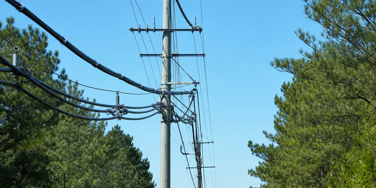
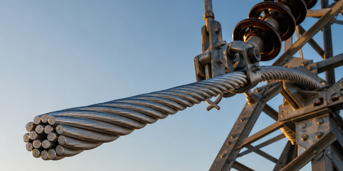
ACSS (Annealed Steel Supported) conductor is the most commercially mature High Temperature Low Sag (HTLS) technology, delivering 50%–100% more ampacity than conventional ACSR conductors of the same size while operating continuously at 200°C. This field guide covers the complete installation and maintenance workflow for ACSS overhead lines — from receiving and storage through stringing, knee-point settling, testing, and a lifetime maintenance schedule — written for transmission engineers, line construction crews, and maintenance managers.
Introduction
Transmission line uprating with ACSS is one of the fastest-growing practices in modern grid engineering. Because ACSS uses the same code words, outer diameters, and weights as standard ACSR conductors, existing towers can typically be reused without structural modification, making it the lowest-cost route to a 1.5–2× capacity increase. However, ACSS is not installed exactly like ACSR. Fully annealed (O-temper) aluminum strands behave very differently under tension and temperature, and every phase of the job — stringing tension, sheave selection, dead-end hardware, the first heat-up cycle — must account for the conductor's plastic-relaxation mechanism.
This guide is the field companion to our ACSS Conductor Complete Technical Guide, which covers standards, specifications, and selection in depth. Here we focus on practical execution: what to check on the drum, which tools to bring, how to compute stringing tension with knee-point creep (KCM) allowance, how to run the settling cycle, and what to inspect for the next 10 years. All procedures reference IEEE 524 (Chapter 15 is dedicated to ACSS installation), ASTM B857, IEC 61089, IEEE 738, and CIGRE TB 244/324.
Pre-Installation Preparation
Receiving and Storage
The single most important difference between ACSS and ACSR begins at the warehouse: annealed aluminum is softer and more easily damaged than hard-drawn wire. Follow this inspection checklist at receipt:
| Check item | Acceptance criteria |
|---|---|
| Drum condition | No broken lagging, no impact damage; rotate drum on its axis, never lay flat |
| Conductor surface | No abrasion, kinks, or bird-caging on outer layer; annealing produces a matte finish — this is normal, not a defect |
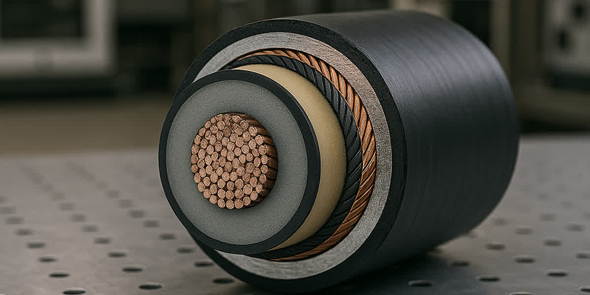
| Core condition | Galvanized or aluminized steel core strands free of rust or coating damage |
| End seals | Both ends sealed; if open, check for moisture ingress and oxidation |
| Documentation | Mill test certificate per ASTM B857 (tensile, conductivity ≥63% IACS, stranding) |
Storage rules: Store drums upright on a firm, drained surface. If stored more than 6 months, rotate each drum 180° every 3 months to prevent core-strand creep in the lower layers. Keep the conductor shaded: prolonged UV exposure degrades the steel-core coating less than it affects marking, but high ambient temperature accelerates aluminum oxidation — keep storage below 40°C where possible. Minimum installation temperature is –10°C; below this, the annealed aluminum becomes brittle and special warming procedures are required.
Tools and Equipment Checklist
| Tool category | Items | Application notes |
|---|---|---|
| Stringing | Bullwheel puller, tensioner with dynamometer, pilot line (synthetic, no steel rope in contact with conductor) | Max pulling tension per design (typically 15%–25% RTS) |
| Running gear | Stringing blocks (sheaves) min 25× conductor OD, swivels, grips | ACSS allows 25× vs 30× for ACSR due to flexibility, but never below 25× |
| Splicing | Full-tension compression dies, hydraulic press ≥100 MPa, steel-core and aluminum dies | Dies are size-specific — ACSS annealed aluminum requires lighter crimping pressure than ACSR |
| Hardware | High-temperature dead-ends, suspension clamps, armor rods, Stockbridge dampers | ALL hardware must be rated for 200°C continuous / 250°C emergency |
| Measurement | Sag boards or laser range finder, tension dynamometer, digital pyrometer/thermocouple, infrared camera | Sag by instrument, never by eye |
| Grounding | Portable grounding clusters, conductive earth mats | Induced voltage on de-energized lines near live circuits |
Installation Plan
- Identify ruling span and sag points; mark all crossing protections (roads, railways, LV lines).
- Sequence: pull in the direction of decreasing span difficulty; plan drum set-up so splices fall at design-approved locations (typically ≥15 m from suspension points and ≥30 m from dead-ends).
- Pre-arrange the KCM settling cycle with the grid operator — you will need controlled current for 1–2 hours after stringing.
- Review hardware temperature ratings on the bill of materials: standard ACSR dead-ends (rated 90°C) must be replaced with 200°C+ hardware.
Engineering Calculations
Sag-Tension with Knee-Point (KCM) Allowance
ACSS sag-tension is a two-regime problem. Below the knee point (≈80°C–100°C), the aluminum and steel share the load elastically. Above it, the annealed aluminum relaxes plastically and the tension transfers to the steel core. The result is a permanent sag increase — the knee-point creep — that must be pre-planned. The composite-model approach follows CIGRE TB 324:
- Initial condition: Compute sag at stringing temperature using the initial (elastic) modulus combining aluminum and steel.
- Knee-point condition: At 175°C+, aluminum stress → 0. Recompute with the steel core alone (E ≈ 190 GPa, α ≈ 11.5×10⁻⁶/°C for galvanized steel; 12.6×10⁻⁶/°C for aluminized).
- Final condition: The difference between the two sag values is the permanent settling sag. The final sag-temperature curve is computed on the steel-core-only model.
Three accepted ways to manage KCM settling (choose one in design):
| Method | Procedure | Best for |
|---|---|---|
| Over-tensioning | String at higher initial tension so settling lands on final design sag | Short lines, simple profiles |
| Two-stage construction | String → heat to 200°C for 1–2 h with controlled current → re-sag to final | Lines where sag accuracy is critical (crossings) |
| Design margin | Reserve 0.3–0.5 m sag allowance in clearance design | Rapid schedules; settling accepted in service |
💡 Rule of thumb: For a typical 400 mm² class line, the KCM settling sag is roughly 1%–2% of the ruling span length. Verify with the CIGRE TB 324 composite model for your exact span.
Stringing Tension and Pulling Limits
- Initial stringing tension: 15%–25% of final design tension for most spans; use the lower bound on long spans.
- Maximum pulling tension: 20% of RTS (ACSS aluminum is annealed — never exceed this).
- Sidewall pressure: limit to 730 kg/m (IEEE 1185 guidance for aluminum conductors; ACSS is more forgiving but the limit protects the soft outer layer).
- Creep compensation: ACSS has essentially no in-service creep after settling (the aluminum is already fully annealed). Do not apply ACSR creep allowances; the settling cycle replaces them.
Installation Procedure
Follow these 8 steps. The two that differ most from ACSR practice are Step 4 (pulling limits) and Step 7 (KCM settling).
| Step | Activity | Requirements |
|---|---|---|
| 1 | Route survey and crossing protection | Confirm sag points, install crossing guards, verify hardware temp ratings |
| 2 | Drum set-up and pilot line | Synthetic pilot line only; never pull steel rope against conductor |
| 3 | Stringing block installation | Sheaves ≥25× OD; check grooves are clean, no burrs |
| 4 | Pulling and tensioning | Pull ≤20% RTS; tensioner maintains sag control; watch for abrasion at block exits |
| 5 | Clip-in and sagging | Sag by instrument to design value at stringing temperature; install suspension clamps with armor rods at all attachment points |
| 6 | Dead-ending and splicing | Full-tension compression dead-ends rated 200°C+; splice per manufacturer die chart; micro-ohmmeter check ≤1.1× conductor resistance |
| 7 | KCM settling cycle | Apply controlled current to reach 200°C for 1–2 h; monitor sag; allow permanent settling; re-sag if two-stage method used |
| 8 | Vibration mitigation | Install Stockbridge dampers per IEEE 664 study; armor rods at all clamps; spacer-dampers for bundles |
⚠️ Never pull ACSS with steel grips directly on the aluminum; use Kellems-style pulling grips over the full circumference or compression pulling eyes.
Splicing Rules
- Use connector systems rated for 210°C continuous (e.g., IEC 61238-1 Class A).
- Crimp pressure is lower than for ACSR — annealed aluminum deforms more easily; follow the die chart exactly.
- Two-piece full-tension splices for sizes ≥400 mm²; steel-core compression first, then aluminum sleeve.
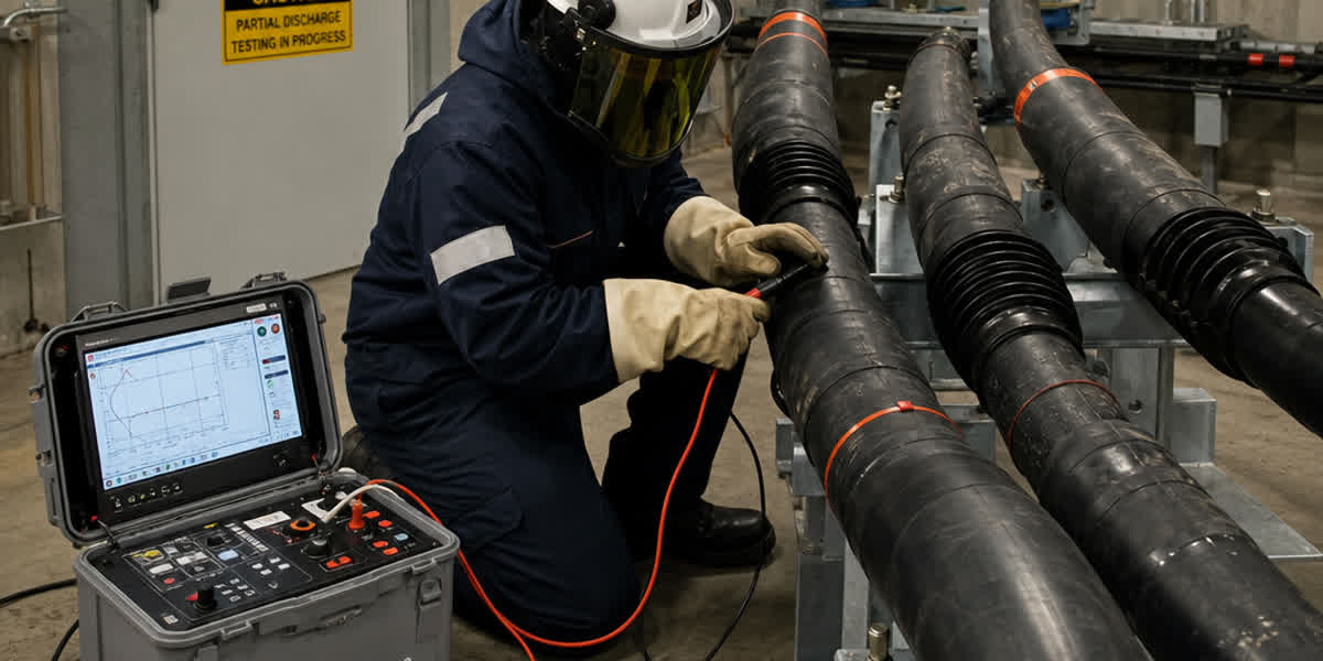
- After each splice: resistance check with micro-ohmmeter (≤1.1× equivalent conductor length) and thermal imaging after first load cycle.
Post-Installation Inspection & Testing
| Inspection item | Acceptance criteria |
|---|---|
| Sag verification | Within ±2% of design at reference temperature |
| Splice resistance | ≤1.1× conductor resistance; no hot spots under load |
| Clearance check | Ground clearance at max design temperature (200°C) meets statutory minimum |
| Hardware temperature | All clamps/dead-ends rated 200°C+; verify markings |
| Corona / radio interference | CISPR 18-2 limits for the voltage class (e.g., RI ≤ 62 dB above 1 μV at 1 MHz for 230 kV class) |
| Vibration dampers | Correct spacing per design; no loose hardware |
| Thermal baseline | Infrared survey after first full-load day; record baseline for trend analysis |
Routine Maintenance Schedule
| Frequency | Activity |
|---|---|
| Monthly (first year) | Thermal imaging of all splices and dead-ends after peak load |
| Quarterly | Aerial patrol: bird-caging, abrasion, foreign objects, damaged armor rods |
| Semi-annual | Sag measurement at known temperature; trend vs. baseline |
| Annual | Infrared survey of full line; check damper condition and spacing |
| 3 years | Sample clamp torque; inspect suspension points for fretting |
| 5 years | Detailed conductor surface inspection (oxidation, broken strands); verify core condition at representative spans |
| 10 years | Full condition assessment; re-verify ampacity model against measured temperatures |
💡 Thermal threshold rule: If any splice runs more than 10°C above the conductor surface temperature at the same load, investigate immediately — developing high-resistance joint. More than 20°C differential = schedule outage and re-terminate.
Troubleshooting Common Issues
| Problem | Likely cause | Solution |
|---|---|---|
| Sag greater than design after settling | KCM allowance underestimated | Re-run sag-tension with steel-core model; adjust tension at next outage |
| Bird-caging during pulling | Excessive tension or small sheaves | Stop pull; inspect damage length; splice out damaged section |
| Hot splice (ΔT > 10°C) | Improper crimp pressure or wrong die | Re-terminate with correct die; verify with micro-ohmmeter |
| Vibration damage at clamp | Missing/undersized dampers, wrong spacing | Install dampers per IEEE 664 study; repair conductor |
| Aluminum strand breakage at dead-end | Bending fatigue from soft aluminum | Add armor rods; use larger-radius dead-end |
| Corrosion on steel core | Coating damage in coastal/industrial service | Specify aluminized core or Class C galvanizing; apply repair sleeves |
| Annealed aluminum abrasion | Debris in sheave grooves or contact with steel rope | Inspect running gear before pull; use synthetic pilot line |
| RI/corona noise above limit | Sharp hardware edges or damaged strands | Smooth hardware, replace damaged strands, re-check CISPR 18-2 |
Safety Considerations
| Hazard | Precaution |
|---|---|
| Induced voltage on de-energized line | Ground both sides of work zone; portable grounding clusters; treat as live until bonded |
| High pulling tension | Stand clear of tensioner/puller line of fire; use rated rigging; 20% RTS max |
| Falls during clip-in | Full fall protection at towers; work platforms for suspension points |
| KCM settling heat cycle | Conductor surface reaches 200°C — do not touch; warn crews below; coordinate with dispatch |
| Live-line proximity | Maintain approach distances per local utility rules (e.g., 3.7 m for 230 kV) |
| Annealed aluminum brittleness below –10°C | Defer work or warm conductor; no bending below minimum temperature |
Frequently Asked Questions (FAQ)
Q1: Can existing ACSR hardware be reused for ACSS?
No. Standard ACSR dead-ends, splices, and suspension clamps are typically rated for 90°C–100°C continuous operation. ACSS requires hardware rated 200°C+ for continuous and 250°C for emergency operation. Reusing 90°C hardware on a 200°C conductor creates a guaranteed hot-spot failure point. Budget for replacing all compression hardware; towers and insulators are normally reusable.
Q2: What is the knee-point settling, and does it hurt the line?
The knee point is the temperature (≈80°C–100°C) at which annealed aluminum begins to relax plastically instead of elastically. During the first heat-up above 175°C, the aluminum permanently transfers its share of tension to the steel core, causing a one-time sag increase. It is a designed, predictable behavior — not damage. Properly managed (over-tensioning, two-stage construction, or design margin), the line reaches its final design sag and is stable for all subsequent thermal cycles.
Q3: What is the maximum stringing tension for ACSS?
Pull at no more than 20% of RTS, with initial stringing tension at 15%–25% of final design tension. The annealed aluminum has only 50%–60% of the tensile strength of hard-drawn wire, so over-pulling causes bird-caging and strand damage. Use a dynamometer on every pull.
Q4: Why does ACSS need 200°C-rated hardware when ACSR runs at 90°C?
ACSS is designed to operate at 200°C continuous and 250°C short-term emergency. Every component in the current path — dead-ends, splices, jumpers, and their connector bodies — must have matching thermal ratings, otherwise the hardware becomes the bottleneck and fails while the conductor is still healthy. High-temperature hardware typically uses aluminum-zirconium alloys or specially designed steel bodies.
Q5: How is ACSS maintenance different from ACSR?
Three differences dominate: (1) thermal imaging is a first-class tool — splices and dead-ends must be surveyed monthly in the first year; (2) vibration management matters more at attachment points because annealed aluminum is more fatigue-sensitive, so dampers and armor rods are mandatory, not optional; (3) after the initial settling, sag is remarkably stable — a sag change in service usually indicates a real problem (broken strand, slipped clamp) rather than normal creep, so investigate rather than re-sag.
Q6: Can ACSS be installed on existing ACSR towers without modification?
In nearly all cases, yes — this is the core value proposition. ACSS uses identical code words, so outer diameter, weight, and RTS match the ACSR it replaces. Verify insulator strings, dead-end structures, and foundation condition in design; only hardware (clamps, dead-ends, splices) must be upgraded to high-temperature ratings. For AAAC or all-aluminum AAC lines, tower verification is still required because mechanical loads differ.
Q7: How long does an ACSS line last?
30–40 years at normal operation ≤200°C. Because the aluminum is already fully annealed, no further softening occurs in service; the dominant aging mechanisms are oxidation and steel-core corrosion. In coastal or industrial environments, specify aluminized steel core or Class C galvanizing to protect the core at elevated temperature.
Q8: When should the settling cycle be done — immediately or later?
Immediately, within days of stringing, while the line is still accessible and before it goes into full service. Delaying the settling cycle means the permanent sag increase happens under load at an uncontrolled moment (often during the first heat wave). A controlled 1–2 hour heat-up to 200°C with monitored sag converts the uncertainty into a known final condition.
References and Standards
| Standard | Description |
|---|---|
| ASTM B857 | Concentric-Lay-Stranded Aluminum Conductors, Coated Steel Supported (ACSS) — primary product standard |
| ASTM B802/B498 | Zinc-coated steel core wire requirements |
| ASTM B609 | Aluminum 1350 wire, annealed (O temper) |
| IEC 61089 | Round wire concentric lay overhead stranded conductors |
| IEEE 524 | Installation of overhead transmission line conductors (Ch. 15: ACSS) |
| IEEE 738 | Current-temperature relationship of bare overhead conductors |
| IEEE 664 | Acoustic vibration / damper application |
| IEEE 1185 | Sidewall pressure limits |
| IEC 61395 | Creep test procedures for stranded conductors |
| IEC 61238-1 | Compression connectors (Class A, 210°C) |
| CIGRE TB 244 | Thermal behaviour of overhead conductors |
| CIGRE TB 324 | Sag-tension calculation methods |
| CISPR 18-2 | Radio interference limits for overhead lines |
Conclusion
ACSS installation is not difficult — it is different. The three rules that keep a project on schedule and on sag are: string soft (≤20% RTS, 25× OD sheaves), settle early (controlled 200°C cycle within days of stringing), and inspect thermally (monthly splice surveys in the first year). Everything else follows standard overhead-line practice, which is exactly why ACSS remains the most cost-effective HTLS choice for grid uprating programs worldwide.
SiTong Cable manufactures ACSS and ACSS/TW conductors to ASTM B857, IEC 61089, and IEEE 524, with full project support from ampacity calculation to field supervision. For line-specific sag-tension studies, hardware selection, or a quotation, contact our engineering team.
👉 Browse our ACSR conductor range 👉 ACSS Conductor Complete Technical Guide: Standards, Specifications & Selection 👉 Contact our team
📬 Sales inquiries: sales@sitongcable.com | 📞 Phone: +86-371-69176007
This guide was prepared by the SiTong Cable engineering team. All technical data references ASTM B857, IEC 61089, IEEE 524, IEEE 738, and CIGRE TB 244/324.