Lead Sheathed Power & Control Cables for Refineries & Petrochemical Plants: Chemical Resistance, Hydrocarbon Barrier Physics, and IEC 60502 / EN 50288 Engineering
Lead Sheathed Power & Control Cables for Refineries & Petrochemical Plants: Chemical Resistance, Hydrocarbon Barrier Physics, and IEC 60502 / EN 50288 Engineering
In petrochemical complexes, oil refineries, LNG export terminals, and chemical processing plants, electrical distribution and instrumentation systems operate under severe environmental conditions. Hydrocarbon solvent penetration, corrosive aromatic vapors, hydrogen sulfide (H₂S), crude condensates, and aggressive acidic or alkaline subsoil moisture degrade conventional thermoplastic (PVC) and thermoset (XLPE) cable sheathing within months. When volatile hydrocarbons permeate a cable jacket, polymers swell, lose tensile strength, and allow solvents to dissolve insulation materials, causing insulation resistance collapse, catastrophic phase-to-ground faults, and explosive arcing in hazardous Zone 1 and Zone 2 environments.
To provide continuous, lifelong protection in contaminated soil and harsh chemical atmospheres, process engineers and industrial facility designers mandate lead sheathed cables (commonly designated with metallic code Q or Pb, e.g., XLPE/Lead/SWA/PVC or XLPE/Lead/AWA/PE). Extruded lead sheath acts as an absolute radial barrier—impermeable to liquid hydrocarbons, aromatic compounds (benzene, toluene, xylene), and aggressive ground chemicals.
This comprehensive technical guide examines the metallurgical properties of lead sheaths, chemical permeability physics, mechanical cable construction, ampacity and earth-loop considerations, and manufacturing standards per IEC 60502-1, IEC 60502-2, IEC 60840, and EN 50288.
1. The Physics of Hydrocarbon Permeability & Chemical Attack
Polymeric sheaths such as Polyvinyl Chloride (PVC), High-Density Polyethylene (HDPE), and Low-Smoke Zero-Halogen (LSZH) are widely specified for commercial, utility, and standard industrial installations. However, semi-crystalline and amorphous polymers contain intermolecular free volume through which low-molecular-weight hydrocarbons readily diffuse via Fickian diffusion.
Polymer Jacket Hydrocarbon Attack Mechanism:
Hydrocarbon Liquid / Vapor Exposure
       │
       ▼
Sorption onto Outer Polymer Surface
       │
       ▼
Fickian Diffusion through Intermolecular Matrix (Swelling & Micro-cracking)
       │
       ▼
Permeation into Bedding & Core Insulation (XLPE/EPR Swelling)
       │
       ▼
Dielectric Breakdown (Treeing / Phase-to-Ground Arc Flash)
In contrast, metallic barriers offer zero organic solubility. Extruded seamless lead alloy forms an atomic metallurgical lattice that completely prevents solvent migration:
| Chemical Agent / Environmental Hazard | Standard PVC / PE Sheath | Polyamide (Nylon) + AL Barrier | Extruded Seamless Lead Sheath (Pb) |
|---|---|---|---|
| Aromatic Hydrocarbons (Benzene, Toluene, Xylene) | Severe swelling, softening, and extraction of plasticizers | Moderate resistance (adhesive bond susceptible to delamination) | Completely Impervious (Zero Diffusion) |
| Aliphatic Hydrocarbons (Gasoline, Diesel, Kerosene) | Significant swell and embrittlement over time | Good resistance | Completely Impervious (Zero Diffusion) |
| Crude Condensates & Lube Oils | Accelerated environmental stress cracking (ESCR) | Moderate resistance | Completely Impervious (Zero Diffusion) |
| Hydrogen Sulfide (H₂S) & Sour Gas | Slow permeation causing copper conductor sulfidation | Potential corrosion at longitudinal seam | Highly Resistant (Forms passive lead sulfide PbS patina) |
| Chlorides, Moisture & Ground Water | Slow water vapor transmission causing water treeing | Moisture resistant if foil seal remains intact | Absolute hermetic radial barrier (Zero moisture transmission) |
| Expected Lifespan in Refineries | < 3–5 years | 10–15 years (subject to mechanical flexing damage) | 30–50+ years of continuous service |
When specifying industrial cabling, plant operators rely on robust power cable range and specialized control cable assemblies engineered with continuous lead barriers to guarantee process uptime and prevent hazardous atmosphere ignition.
2. Lead Metallurgy & Alloy Selection for Industrial Cables
Unalloyed pure lead exhibits high ductility but low creep resistance and poor vibration endurance. Under cyclic thermal expansion and industrial plant vibration (pumps, compressors, structural pipe racks), unalloyed lead can develop intercrystalline cracking along grain boundaries.
Cable manufacturers utilize specific lead alloys standardized under BS EN 12548 and IEC 60055-1 to deliver optimal fatigue resistance and metallurgical stability:
Lead Sheath Alloys for Cable Manufacturing:
├── Lead Alloy E (BS EN 12548)
│   ├── Composition: 0.40% Antimony (Sb), 0.15% Arsenic (As), 0.10% Bismuth (Bi), Balance Pb
│   └── Characteristics: Superior fatigue endurance, designed for aerial, pipe-rack & vibrating environments
├── Lead Alloy 1/2 C (BS EN 12548)
│   ├── Composition: 0.20% Tin (Sn), 0.075% Cadmium (Cd), Balance Pb
│   └── Characteristics: Excellent creep resistance and extrusion stability, standard for direct-buried refinery feeders
└── Pure Chemical Lead (99.9% Pb)
    └── Limited strictly to stationary, non-vibrating, unarmoured short duct runs
Extrusion Technology & Quality Control
At SiTong Cable (Zhengzhou Sitong Cable Co., Ltd.), continuous screw extruders apply lead alloy under precise temperature zones (300°C–320°C). Continuous extrusion eliminates the circumferential weld seams (stop-marks) inherent in older vertical ram presses, guaranteeing uniform radial thickness, non-eccentric grain formation, and complete absence of micro-porosity.
3. Structural Anatomy of Lead Sheathed Refinery Cables
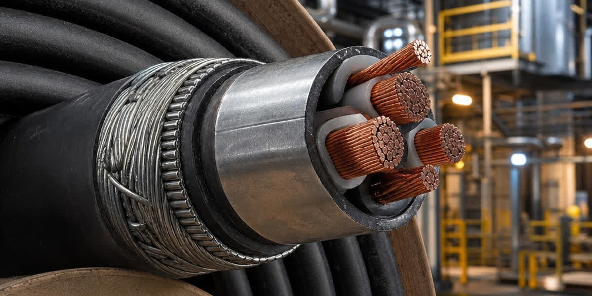
A heavy-duty lead sheathed power or control cable is a multi-layer composite system where each element performs a critical mechanical, electrical, or chemical function:
Cross-Sectional Anatomy of a 3-Core MV Lead Sheathed Power Cable:
[Conductor] ──── Compacted Class 2 Stranded Copper / Aluminum (IEC 60228)
     │
[Conductor Screen] ─ Extruded Semi-Conducting Compound (0.5 mm)
     │
[Insulation] ──── Triple-Extruded Dry-Cured Tree-Retardant XLPE (TR-XLPE / IEC 60502-2)
     │
[Insulation Screen] Extruded Semi-Conducting Compound + Copper Tape Shield
     │
[Assembly Bedding] Non-Hygroscopic Polypropylene Fillers + Binder Tape
     │
[Lead Sheath] ─── Continuous Extruded Lead Alloy E / 1/2C (Radial Chemical Barrier)
     │
[Separation Sheath] Extruded PVC / LSZH / Polyethylene Cushioning (Protects lead from armor indentation)
     │
[Mechanical Armor] Galvanized Steel Wire Armor (SWA) or Steel Tape Armor (STA)
     │
[Outer Oversheath] Hydrocarbon-Resistant Heavy-Duty PVC / HDPE / Polyamide Jacketing
Key Engineering Features of the Layer Stack:
- Separation Bedding (Under-Armor Cushion): The lead sheath is mechanically soft. Direct application of steel wire or tape armor directly onto lead causes stress indentations during bending. An extruded separation jacket (typically 1.0–1.5 mm of PVC or PE) protects the lead against localized shear forces.
- Metallic Armor: In high-risk refinery processing areas, Steel Wire Armor (SWA) provides longitudinal tensile strength and high impact resistance against excavation equipment. For single-core cables, non-magnetic Aluminium Wire Armor (AWA) is mandatory to eliminate inductive eddy-current heating.
- Outer Oversheath: While the lead protects against internal chemical ingress, an engineered outer sheath (oil-resistant PVC per IEC 60811-404 or UV-stabilized HDPE) defends the cable against external soil abrasion, acid spills, and physical installation strain. In critical enclosed switchgear rooms, low-smoke zero-halogen jackets provide fire performance.
4. Electrical Engineering Considerations: Circulating Currents & Grounding
While lead provides an impermeable barrier, it is also an electrical conductor (resistivity of lead $\rho \approx 22 \times 10^{-8} \ \Omega \cdot \text{m}$ at 20°C, roughly 12 times higher than copper). Consequently, power system engineers must account for induced voltages and thermal short-circuit sizing.
4.1 Induced Voltage and Sheath Bonding Systems
In three-phase single-core cable runs, alternating load currents induce longitudinal voltages along the lead sheath and armor: - Both-Ends Solid Bonding: Eliminates standing voltage along the cable route but allows circulating currents to flow continuously through the lead sheath and earth return path. Due to the electrical resistance of lead, circulating current generates $I^2 R$ heat, requiring a 5% to 15% current-carrying capacity derating of the conductor. - Single-Point Bonding & Cross-Bonding: For long feeder runs between refinery substations and process unit switchgear, single-point bonding with Sheath Voltage Limiters (SVLs) restricts standing touch voltages to $< 65 \text{ V}$ under continuous full load, eliminating circulating currents and restoring maximum conductor ampacity.
4.2 Earth Fault Current Withstand
Under phase-to-ground fault conditions, the lead sheath and metallic armor act in parallel as the earth return fault path. The adiabatic thermal limit of the lead sheath is calculated according to IEC 60949:
$$I_{AD} = A \cdot K \cdot \sqrt{\frac{1}{t} \ln\left(\frac{\theta_f + \beta}{\theta_i + \beta}\right)}$$
Where: - $I_{AD}$ = Short-circuit current capacity (A) - $A$ = Cross-sectional area of the lead sheath ($\text{mm}^2$) - $K$ = Material constant for lead ($K = 41.5 \text{ A}\cdot\text{s}^{1/2}/\text{mm}^2$) - $\beta$ = Reciprocal of temperature coefficient of resistance for lead ($230^\circ\text{C}$) - $\theta_i$ = Initial operating temperature (typically $60^\circ\text{C}$ to $70^\circ\text{C}$) - $\theta_f$ = Maximum permissible final fault temperature ($170^\circ\text{C}$ for lead without joint degradation) - $t$ = Fault clearing duration (s)
For installations with exceptionally high fault levels, plant designers supplement the lead sheath with heavy galvanized steel wire armouring or an embedded copper tape screen to prevent lead melting during sustained ground faults.
5. Specification & Comparison: Lead Sheath vs. Alternative Chemical Barriers
In refinery revamps and engineering bid evaluations, specifying engineers frequently compare lead sheathed designs against alternative synthetic and laminated composite barrier technologies:
| Technical Parameter | Extruded Seamless Lead Sheath (Pb) | Multi-Layer Polyamide (Nylon) Jacket | Corrugated Stainless Steel / Aluminum (CCW / ALS) |
|---|---|---|---|
| Barrier Technology | Extruded seamless metallic tube | Extruded thermoplastic polymer | Continuously welded & corrugated metal tape |
| Benzene / Toluene Permeation Rate | Absolute Zero ($0.00 \text{ g/m}^2/\text{day}$) | $0.05 - 0.20 \text{ g/m}^2/\text{day}$ (gradual diffusion) | Absolute Zero (unless weld fatigue occurs) |
| H₂S Sour Gas Containment | Hermetic; self-passivating surface | Permeable over time | Susceptible to sulfide stress cracking (SSCC) |
| Mechanical Flexibility | Excellent cold bend ductility | Stiff; prone to kinking at sub-zero temperatures | Rigid; large minimum bending radius ($15 \times D$) |
| Vibration Fatigue Resistance | High (using Alloy E with Antimony/Arsenic) | High flexibility | Susceptible to work-hardening and fatigue cracking |
| Corrosion Resistance in Soil | Impervious to common soil acids and sulfates | Excellent organic resistance | Requires protective bitumen/polymeric oversheath |
| Weight Factor | Heavy (approx. $1.5\times - 2.5\times$ standard cable) | Lightweight ($1.0\times$) | Medium-heavy ($1.2\times - 1.4\times$) |
| Terminal Gland Compatibility | Standard explosion-proof Ex d compound glands | Standard compression glands | Specialized corrugated mechanical glands |
| Installed Lifespan in Refineries | 40–50+ Years | 10–18 Years | 25–35 Years |
While aluminum-laminated or nylon sheaths offer lower shipping weight, global petrochemical engineering contractors (including Shell DEP, Saudi Aramco, ExxonMobil, and TotalEnergies specifications) standardize on extruded lead sheathed cables for all direct-buried circuits in hydrocarbon-handling battery limits.
6. Installation, Cable Pulling & Glanding in Hazardous Locations
Proper field installation is essential to maintain the integrity of lead-sheathed cables:
Lead Sheath Cable Installation Best Practices:
├── Minimum Bending Radius
│   ├── During Installation: 15 × Overall Cable Diameter (D)
│   └── Fixed Installed Radius: 12 × Overall Cable Diameter (D)
├── Cable Pulling Force Limits
│   ├── Pulling via Copper Conductor Core: Max 70 N/mm² conductor area
│   ├── Pulling via Pulling Eye / Lead Sheath: Strictly Prohibited
│   └── Maximum Sidewall Bearing Pressure: 5.0 kN/m to avoid lead deformation
└── Explosion-Proof Termination (ATEX / IECEx)
    ├── Certified Ex d / Ex e compound barrier glands (BS 6121 / EN 62444)
    ├── Electrical earth continuity connection to lead sheath via brass cone/skirt
    └── Long-barrel [shear bolt mechanical connectors & cable lugs](/accessories/?first_category=cable_lugs)
- Pulling Tension Control: Never attach pulling grips solely to the outer jacket or lead sheath. Tensile pulling forces must be transmitted directly to the central copper conductor cores using pulling heads, or through wire mesh stockings distributed over double-armored constructions.
- Sidewall Bearing Pressure (SWBP): Keep sidewall pressure below $5 \text{ kN/m}$ ($350 \text{ lbs/ft}$) on conduit and tray bends to prevent ovalization and thinning of the ductile lead barrier.
- Ex d / Ex e Hazardous Area Glands: In classified Zone 1 and Zone 2 areas per IEC 60079-14, termination requires flameproof barrier glands equipped with an internal elastomeric sealing ring and a metal-to-metal bonding ring that clamps directly onto the lead sheath. This ensures high-conductivity earth fault continuity while sealing flammable vapors from migrating into switchgear enclosures. Engineers use industrial pole line and cable support fittings designed for heavy metallic cables to prevent localized fatigue stress on pipe-rack risers.
7. Standards Compliance & SiTong Cable Manufacturing Capabilities
Lead sheathed cables must be manufactured in full compliance with rigorous international petrochemical standards:
| Standard / Specification | Scope & Scope of Application |
|---|---|
| IEC 60502-1 | Power cables with extruded insulation from $1 \text{ kV} (U_m = 1.2 \text{ kV})$ up to $3 \text{ kV}$ |
| IEC 60502-2 | Power cables with extruded insulation from $6 \text{ kV} (U_m = 7.2 \text{ kV})$ up to $30 \text{ kV} (U_m = 36 \text{ kV})$ |
| IEC 60840 | Power cables with extruded insulation for rated voltages from $30 \text{ kV}$ up to $150 \text{ kV}$ |
| EN 50288-7 | Multi-element metallic instrumentation and control cables for petrochemical process automation |
| BS 6346 / BS 5467 | Armoured PVC and XLPE power cables with lead alloy radial sheath option |
| IEC 60332-3-22 (Cat A) | Flame propagation test on bunched vertical cable runs |
| IEC 60079-14 | Explosive atmospheres — Electrical installations design, selection, and erection |
Why Petrochemical EPC Contractors Choose SiTong Cable
SiTong Cable (Zhengzhou Sitong Cable Co., Ltd.) operates state-of-the-art continuous lead extrusion lines equipped with inline ultrasonic wall-thickness monitors and X-ray concentricity gauges. Every production reel undergoes 100% spark testing of extruded jackets, helium micro-leak detection on lead sheaths, and complete AC high-voltage partial discharge verification in our ISO 9001, ISO 14001, and CE-certified testing laboratories. Whether supplying low-voltage refinery lighting circuits, multi-pair instrumentation cables, or 33kV main substation feeders, SiTong Cable delivers engineered reliability to major energy projects across the Middle East, Southeast Asia, South America, and Africa.
Frequently Asked Questions (FAQ)
1. Why is lead still used in refinery cables despite environmental restrictions like RoHS?
Industrial electrical installations in chemical plants and oil refineries are exempted from European RoHS directives under critical industrial infrastructure categories. There is currently no synthetic polymer that matches the absolute chemical impermeability, moisture resistance, and 40+ year service life of extruded lead alloy in saturated hydrocarbon soil environments.
2. Can non-lead cables (such as nylon/polyamide sheaths) be substituted for lead sheathed cables?
Polyamide (Nylon) or aluminum-laminated foil barriers provide moderate resistance to hydrocarbons and are frequently used in above-ground commercial fuel depots. However, in major refineries, petrochemical plants with aromatic compounds (benzene, toluene), and heavy underground crude contamination, nylon sheaths experience gradual plasticizer leaching and moisture migration. Most petrochemical operators strictly prohibit synthetic alternatives for underground process units.
3. How does the lead sheath affect cable ampacity ratings?
Because lead is an electrical conductor, induced alternating voltages generate circulating eddy currents when both ends of the cable are solidly grounded. For single-core cables, this produces thermal losses requiring a 5% to 15% conductor ampacity derating compared to unshielded or plastic-sheathed cables. Multi-core cables experience minimal circulating current losses due to magnetic field cancellation between balanced three-phase cores.
4. What is the difference between Lead Alloy E and Lead Alloy 1/2C?
Lead Alloy E (containing ~0.4% antimony and 0.15% arsenic) is engineered for high mechanical fatigue endurance, making it the preferred choice for cables installed on vibrating pipe racks, aerial supports, or bridge structures. Lead Alloy 1/2C (containing ~0.2% tin and 0.075% cadmium) provides superior creep resistance and uniform extrusion stability, making it the global standard for direct-buried underground power feeders.
5. What type of cable gland is required for lead sheathed cables in hazardous areas?
Lead sheathed cables installed in Zone 1 or Zone 2 hazardous areas require certified explosion-proof (Ex d / Ex e) cable glands compliant with IEC 60079-14. These glands incorporate an inner lead-bonding cone to secure 360-degree electrical grounding contact with the lead sheath, along with a certified compound barrier or silicone sealing displacement ring to block gas migration through the cable interior into electrical equipment.
Technical Consultation & Procurement Support
For project quotations, engineering specifications, or custom lead-sheathed cable designs for oil, gas, and petrochemical facilities, contact the SiTong Cable engineering team:
👉 Browse our complete power cable product range
👉 Explore our industrial control and instrumentation cable range
👉 Contact our engineering team for project quotes and custom designs
📬 Sales & Project Inquiries: sales@sitongcable.com | 📞 Technical Hotline: +86-371-69176007
🏢 Manufacturer: Zhengzhou Sitong Cable Co., Ltd. | ISO 9001 / ISO 14001 / CE Certified Quality