Underground Cable Diagnostic Testing & Fault Locating: Technical Guide to VLF Tan Delta, Partial Discharge, TDR & Sheath Integrity (IEEE 400, IEC 60502-2, IEC 60229)
Underground Cable Diagnostic Testing & Fault Locating: Technical Guide to VLF Tan Delta, Partial Discharge, TDR & Sheath Integrity (IEEE 400, IEC 60502-2, IEC 60229)
Underground power distribution reliability depends on proactive dielectric condition assessment and rapid fault localization. This comprehensive technical guide covers modern non-destructive diagnostics—including VLF 0.1 Hz Tan Delta dissipation factor analysis, offline and online Partial Discharge (PD) screening, DC sheath integrity testing per IEC 60229, and pinpoint fault location methodologies (TDR, Arc Reflection, and Acoustic Thumping). Power engineers, asset managers, and electrical contractors will learn actionable diagnostic thresholds, standard compliance criteria per IEEE 400, IEEE 400.2, and IEC 60502-2, and root-cause degradation mechanisms in modern extruded polymeric insulation systems.
1. Introduction: Condition-Based Maintenance vs. Run-to-Failure in Underground Distribution
Underground medium-voltage (MV) and high-voltage (HV) cable circuits represent high-capital utility infrastructure where unplanned service outages cause severe financial penalties, lengthy excavation delays, and network instability. Historically, utilities relied on time-based maintenance or destructive DC hipoting. However, destructive DC testing on aged solid dielectric cables (cross-linked polyethylene, XLPE) causes space charge accumulation that accelerates treeing degradation and triggers premature insulation breakdown shortly after re-energization.
Modern electrical utility asset management has shifted decisively toward Condition-Based Maintenance (CBM) and Reliability-Centered Maintenance (RCM). By combining global dielectric loss assessment (Tan Delta) with localized defect detection (Partial Discharge) and outer barrier integrity verification (Sheath DC testing), electrical operators can accurately quantify remaining asset life, prioritize capital replacement, and repair localized defects before catastrophic in-service faults occur.
When deploying newly commissioned or retrofitted underground power cable systems, implementing rigorous baseline diagnostic profiling ensures that field installation practices, jointing workmanship, and trench backfilling meet the highest international engineering benchmarks.
2. Dielectric Loss Diagnostics: VLF 0.1 Hz Withstand and Tan Delta ($\tan\delta$) Analysis
Very Low Frequency (VLF) AC testing operating at 0.1 Hz to 0.01 Hz has replaced DC hipoting as the global utility standard for field evaluation of solid dielectric cables. Because capacitive charging current is proportional to frequency ($I_c = 2\pi f C V$), generating a high-voltage test signal at 0.1 Hz requires 500 to 600 times less power and physical equipment weight than a 50/60 Hz power-frequency test set.
2.1 The Dielectric Loss Mechanism and Tan Delta Formulation
In an ideal, un-degraded cable insulation, the dielectric acts as a pure capacitor where the total current leads the applied voltage by 90°. In real polymeric insulation systems, ionic conduction, dipole polarization losses, and water tree sub-microscopic channels create a resistive leakage current component ($I_R$) in parallel with the capacitive current ($I_C$).
The dissipation factor ($\tan\delta$), or loss angle tangent, is mathematically expressed as:
$$\tan\delta = \frac{I_R}{I_C} = \frac{1}{\omega C R_p} = \frac{\epsilon''}{\epsilon'}$$
Where: * $I_R$ is the resistive loss current * $I_C$ is the capacitive charging current * $\omega = 2\pi f$ is the angular frequency (at 0.1 Hz) * $C$ is the cable capacitance * $R_p$ is the equivalent parallel insulation resistance * $\epsilon'$ and $\epsilon''$ are the real (permittivity) and imaginary (loss factor) components of complex dielectric permittivity.
As water trees grow, moisture penetrates the micro-voids of XLPE or TR-XLPE insulation, increasing the resistive current $I_R$ and causing a measurable rise in $\tan\delta$.
2.2 IEEE 400.2 Diagnostic Assessment Criteria
Per IEEE 400.2 (Guide for Field Testing of Shielded Power Cable Systems Using VLF), a three-step voltage ramp is applied: $0.5 U_0$, $1.0 U_0$, and $1.5 U_0$ (where $U_0$ is the phase-to-ground operating voltage). Field condition assessment evaluates three primary statistical parameters:
- Mean Tan Delta (Mean TD at $U_0$): Measures the overall bulk degradation of the entire cable length.
- Tan Delta Delta / Tip-Up ($\Delta\text{TD} = \text{Mean TD}{1.5 U_0} - \text{Mean TD}$): Measures voltage dependency. Significant non-linear increase in $\tan\delta$ with voltage indicates severe water treeing or moisture contamination that polarizes under elevated electrical stress.
- Tan Delta Temporal Stability / Standard Deviation ($\text{TD-SD}$ at $U_0$): Measures the time variance across consecutive cycles. High instability indicates active, fluctuating dielectric breakdown processes or moisture tracking across cable terminations.
The following table summarizes diagnostic condition levels for filled and unfilled XLPE, TR-XLPE, and EPR medium voltage power cables (6kV–35kV) per IEEE 400.2 criteria:
| Parameter at 0.1 Hz | Condition: No Action Required | Condition: Further Study / Action Required | Condition: Action Required / Critical |
|---|---|---|---|
| Mean Tan Delta ($10^{-3}$) | $< 1.2$ (XLPE / TR-XLPE) $< 2.5$ (EPR) |
$1.2 \le \text{TD} \le 2.2$ (XLPE) $2.5 \le \text{TD} \le 5.0$ (EPR) |
$> 2.2$ (XLPE / TR-XLPE) $> 5.0$ (EPR) |
| Differential TD ($\Delta\text{TD}$, $10^{-3}$) | $< 0.6$ (XLPE / TR-XLPE) $< 1.0$ (EPR) |
$0.6 \le \Delta\text{TD} \le 1.0$ (XLPE) $1.0 \le \Delta\text{TD} \le 2.5$ (EPR) |
$> 1.0$ (XLPE / TR-XLPE) $> 2.5$ (EPR) |
| Stability (TD-SD, $10^{-3}$) | $< 0.1$ | $0.1 \le \text{TD-SD} \le 0.4$ | $> 0.4$ |
| Primary Physical Meaning | Clean, dry, homogeneous insulation | Moderate water treeing, localized moisture | Severe treeing, impending thermal/dielectric breakdown |
3. Localized Defect Detection: Partial Discharge (PD) Screening
While Tan Delta provides a macro-level assessment of uniform insulation degradation, it cannot pinpoint isolated macroscopic defects such as metallic burrs, knife cuts in the semiconductor shield, void inclusions, or incorrect joint stress cone positioning. An insulation system can exhibit an acceptable bulk Tan Delta reading while harboring a fatal, localized electrical tree that will fail within hours. Partial Discharge (PD) testing identifies and locates these discrete defects.
3.1 Physics of Partial Discharge and Apparent Charge
A partial discharge is a localized electrical dielectric breakdown of a small portion of a solid or liquid electrical insulation system under high voltage stress, which does not completely bridge the space between two conductors. In extruded solid dielectric cables, PD occurs in gas-filled cavities (voids), delaminations between the insulation and semiconductive screens, or along contaminated interface boundaries of cable joints and terminations.
The discharge magnitude is quantified as apparent charge ($Q_{app}$) in picocoulombs (pC), defined per IEC 60270. The pulse duration of a PD event is measured in nanoseconds, creating high-frequency electromagnetic traveling waves that propagate toward both cable ends.
3.2 Offline vs. Online PD Measurement
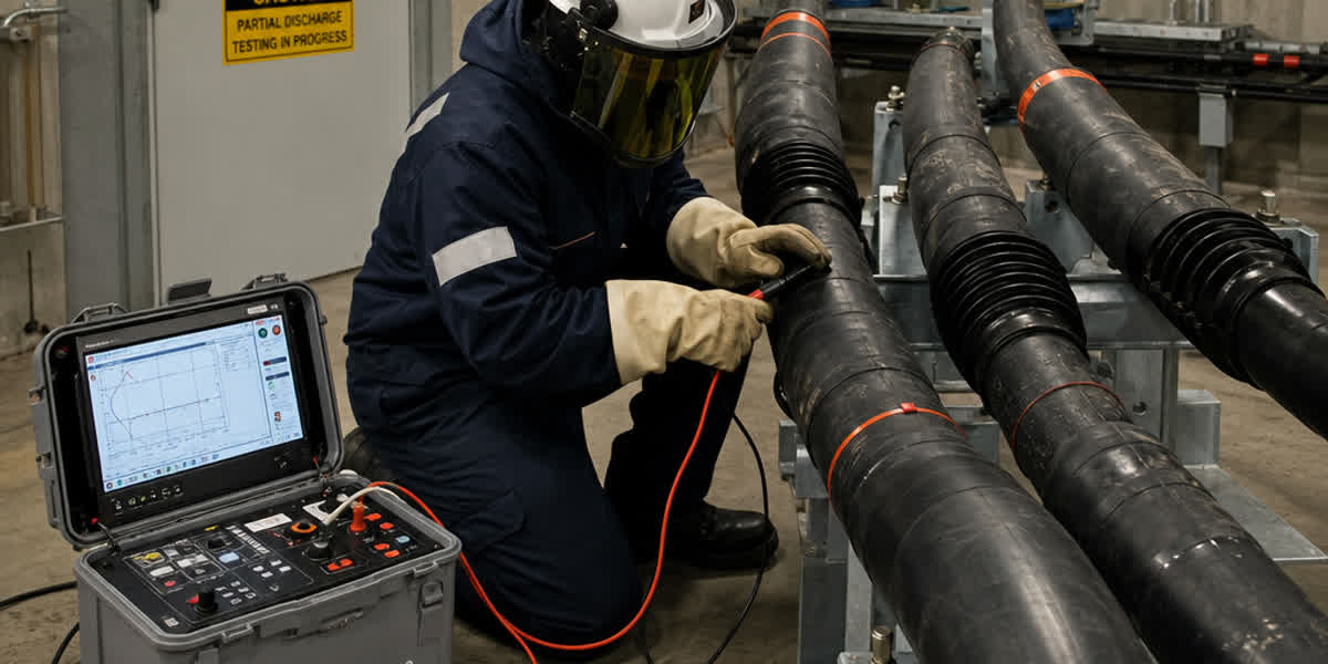
- Offline VLF/DAC Partial Discharge Testing: The cable circuit is de-energized and disconnected from the grid. A high-voltage VLF (0.1 Hz) source or Damped AC (DAC) resonance system energizes the cable up to $1.5 U_0 - 2.0 U_0$. By synchronizing high-frequency current transformers (HFCT) or capacitive couplers with time-domain reflectometry, the exact position of the PD source (in meters from the test terminal) is pinpointed using the pulse propagation velocity ($v \approx 160\text{--}180\text{ m}/\mu\text{s}$ in XLPE).
- Online Partial Discharge Monitoring: The cable remains energized under normal operating load. Non-invasive HFCT sensors are clamped around cable shield grounding straps, or acoustic and transient earth voltage (TEV) sensors are placed on cable terminations. Advanced digital noise filtering algorithms (wavelet analysis, phase-resolved partial discharge PRPD pattern clustering) separate real insulation discharge from environmental background noise and power electronic switching interference.
3.3 Phase-Resolved Partial Discharge (PRPD) Pattern Diagnostics
Analyzing the phase relationship between the PD pulses and the reference AC voltage cycle reveals the physical root cause of the defect:
- Internal Cavity / Void Discharge: Symmetric PD clusters located in the first and third quadrants (around the zero-crossing of voltage where $dV/dt$ is maximum). Equal positive and negative discharge magnitudes.
- Surface / Interface Tracking in Joints: Asymmetric discharge pulses occurring near the voltage peaks, exhibiting high repetition rates and rapid magnitude expansion with increasing test voltage.
- Corona Discharge in Air: Occurs strictly at negative voltage peaks on sharp metallic points, showing extremely uniform pulse height distribution.
For modern single-core and three-core distribution systems, including service entrance and concentric cable configurations, routine PD baseline screening during post-installation commissioning guarantees that accessory assembly workmanship conforms to manufacturer specifications.
4. Outer Sheath Integrity Testing & DC Voltage Withstand (IEC 60229)
The non-metallic outer oversheath (typically HDPE, MDPE, or PVC) serves as the primary environmental barrier protecting the metallic screen (copper wire screen or copper tape) and radial moisture barriers from water ingress, chemical attack, and electrochemical ground corrosion.
A puncture or gouge in the outer sheath allows ground water and dissolved corrosive ions to contact the metallic screen. In un-bonded or single-point bonded networks, this moisture creates galvanic cells that corrode the screen wires, destroying system short-circuit rating and initiating water treeing in the underlying insulation.
4.1 Field Sheath Testing Procedure (IEC 60229 / IEEE 400)
- Isolation: Disconnect all sheath grounding links at both ends (substation end and remote termination or link box).
- High Voltage DC Application: Connect a DC high-voltage test set between the metallic screen and the substation earth grid.
- Voltage and Duration Parameters:
- Commissioning Test (New Cables): Apply 10 kV DC for 1 minute (for sheath thickness $\ge 2.0\text{ mm}$ per IEC 60229).
- Maintenance Test (Service-Aged Cables): Apply 5 kV DC for 1 minute.
- Pass/Fail Acceptance Criteria: The leakage current must remain stable over the test duration. Insulation resistance must exceed $10\text{ M}\Omega\cdot\text{km}$ ($R_{sheath} \ge 100\text{ M}\Omega$ for typical urban feeder runs $< 5\text{ km}$). A sudden jump or continuous increase in DC leakage current indicates moisture ingress through a sheath pinhole.
4.2 Pinpointing Sheath Faults via Step-Voltage Gradient (A-Frame)
When a sheath integrity test fails, pinpoint localization is executed using the DC Step-Voltage Gradient method: 1. An audio-frequency pulsed DC transmitter (typically 1 Hz to 4 Hz, 0.5 kV to 5 kV) is connected between the cable shield and earth. 2. The pulsed current leaks into the surrounding soil exclusively at the point of the sheath puncture. 3. The field engineer walks along the buried cable route with an earth gradient receiver and two metallic probes (A-Frame) inserted into the ground. 4. As the operator approaches the fault, the voltmeter indicates a rising voltage gradient; directly above the sheath breach, the polarity reverses, pinpointing the puncture within $\pm 10\text{ cm}$.
5. Post-Fault Localization Workflow: From Pre-Locating to Pinpointing
When an underground cable experiences a catastrophic dielectric puncture, identifying the fault position rapidly minimizes consumer outage times (SAIDI/SAIFI indices) and avoids disruptive trial trenching.
+-----------------------------------------------------------------------------------+
|                        UNDERGROUND CABLE FAULT LOCATING WORKFLOW                   |
+-----------------------------------------------------------------------------------+
                                          |
                                          v
                [Step 1: Fault Characterization & Insulation Resistance]
                - Megohmmeter (1000V/2500V DC): Core-to-Earth, Core-to-Core
                - Determine Fault Type: Open Circuit, Low-Resistance (<100Ω),
                  High-Resistance / Flashover (>100Ω), Sheath Pinhole
                                          |
                                          v
                [Step 2: Pre-Location (Distance Measurement from Terminal)]
                +-------------------------+-----------------------------------------+
                | Low Resistance / Open   | High Resistance / Intermittent Arcing   |
                +-------------------------+-----------------------------------------+
                | TDR (Pulse Reflection)  | - Arc Reflection Method (ARM / TDR)     |
                | - Transmit LV pulse     | - Impulse Current Method (ICM)          |
                | - Calculate distance via| - Decay Method (High Voltage Traveling  |
                |   wave velocity & time  |   Wave)                                 |
                +-------------------------+-----------------------------------------+
                                          |
                                          v
                [Step 3: Route Tracing & Depth Determination]
                - Audio Frequency Generator (e.g., 9.8 kHz / 33 kHz)
                - Electromagnetic Line Locator (Peak/Null antenna mode)
                                          |
                                          v
                [Step 4: Pinpoint Acoustic / Thumping Localization]
                - High-Voltage Surge Generator (Capacitor Discharge Thumper)
                - Ground Microphone & Electromagnetic-Acoustic Coincidence Receiver
                - Measure propagation time delay between magnetic pulse & acoustic bang
                                          |
                                          v
                [Step 5: Excavation, Inspection & Permanent Joint Repair]
                - Verify physical damage; install compression sleeve & cold-shrink joint
                - Re-test with VLF and Sheath DC before energization
5.1 Time Domain Reflectometry (TDR / Cable Radar)
TDR transmits a low-voltage nanosecond pulse along the cable core. At any impedance change ($Z_0 = \sqrt{L/C}$), a portion of the incident pulse reflects back to the transmitter. The distance $d$ to the impedance discontinuity is calculated as:
$$d = \frac{v \cdot t}{2} = \frac{c}{\sqrt{\mu_r \epsilon_r}} \cdot \frac{t}{2}$$
Where $v$ is the pulse velocity ($v \approx 160\text{ m}/\mu\text{s}$ for XLPE insulation), $t$ is the two-way transit time, and $\epsilon_r \approx 2.3$ is the dielectric constant of cross-linked polyethylene. * An Open Circuit fault produces a reflected pulse with the same polarity (+). * A Low-Resistance Short Circuit produces a reflected pulse with the inverted polarity (-).
5.2 High-Resistance Fault Pre-Location: Arc Reflection Method (ARM)
Because over 85% of underground cable failures in polymeric insulation manifest as high-resistance flashovers ($R_{fault} > 100\,\Omega$ or active arc breakdown), standard low-voltage TDR cannot register a reflection.
The Arc Reflection Method (ARM) combines a high-voltage surge generator (thumper) with a transient filter and TDR: 1. The thumper fires a high-voltage pulse that breaks down the fault gap, creating a low-impedance ionized electric arc for several milliseconds. 2. While the arc is burning (behaving as a momentary short circuit), the TDR sends a low-voltage radar pulse. 3. The TDR pulse reflects strongly off the temporary arc. 4. By overlaying the un-discharged baseline TDR trace with the arc reflection trace, the exact crossover point reveals the fault distance with sub-meter precision.
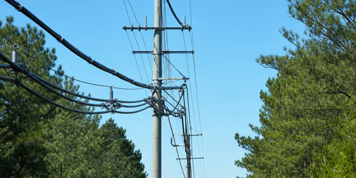
During permanent joint repair and termination rebuilding, ensuring high-conductivity compression cable lugs and bimetallic terminals and robust mechanical clamping prevents thermal hotspots and secondary contact failures. When overhead-to-underground transition risers are installed, heavy-duty overhead transmission line fittings and pole hardware ensure strain relief and lightning arrester grounding.
6. Comprehensive Diagnostic & Fault Locating Matrix
The following engineering matrix compares primary field diagnostic and fault locating methodologies according to international standards, detection targets, and field utility applications:
| Diagnostic / Locating Method | Target Defect Type | Operating Voltage / Signal | Governing International Standard | Field Application Phase |
|---|---|---|---|---|
| VLF Tan Delta ($\tan\delta$) | Bulk water treeing, moisture ingress, overall insulation aging | $0.5 U_0 \text{ to } 1.5 U_0$ (0.1 Hz VLF sinusoidal) |
IEEE 400.2, IEC 60502-2, DIN VDE 0276-620 | Commissioning baseline & scheduled CBM condition assessment |
| Offline Partial Discharge (PD) | Discrete voids, electrical trees, poor joint workmanship | $1.0 U_0 \text{ to } 2.0 U_0$ (VLF or Damped AC DAC) |
IEEE 400.3, IEC 60270, CIGRE WG B1.28 | Factory QA, post-installation commissioning, critical asset audit |
| Online PD (HFCT / Acoustic) | In-service insulation tracking, termination corona, joint deterioration | System operating voltage $U_0$ (High frequency 50kHz–50MHz) |
IEC 62478, IEEE 1434 | Non-intrusive live monitoring of critical substation feeders |
| DC Sheath Integrity Test | Pinhole punctures, gouges, mechanical jacket damage | 5 kV – 10 kV DC (1 min withstand) | IEC 60229, IEEE 400, CIGRE TB 283 | Post-trench backfill commissioning & annual maintenance |
| A-Frame Step Voltage | Pinpoint location of outer sheath punctures | $0.5\text{--}5\text{ kV}$ pulsed DC (1–4 Hz) | IEEE 400, DIN EN 50399 | Post-sheath test failure pinpointing before excavation |
| Time Domain Reflectometry (TDR) | Open circuit cuts, metallic solid shorts, length verification | Low voltage pulse ($\pm 10\text{V to } 100\text{V}$, nanosecond) | IEEE 1234, IEC 60502-2 | Rapid preliminary fault screening & total length measurement |
| Arc Reflection Method (ARM) | High-resistance faults, wet flashover punctures, intermittent arcs | $5\text{--}35\text{ kV}$ surge + TDR pulse reflection | IEEE 1234 | Pre-locating buried cable punctures with high precision |
| Acoustic / Magnetic Pinpointing | Precise spatial location of underground discharge arc | Surge discharge (thump energy 500J – 2000J) | IEEE 1234 | Field excavation pinpointing ($\pm 0.2\text{ m}$ accuracy) |
7. SiTong Cable Factory Quality Assurance & Defect-Free Manufacturing Standards
Field diagnostics are designed to catch defects, but the ultimate defense against underground cable failure is zero-defect manufacturing. Zhengzhou SiTong Cable Co., Ltd. (SiTong Cable) implements end-to-end quality control systems certified to ISO 9001:2015, ISO 14001:2015, and OHSAS 18001, ensuring every meter of manufactured cable exceeds international performance thresholds.
- Triple Co-Extrusion CCV Line: SiTong utilizes state-of-the-art Continuous Catenary Vulcanization (CCV) extrusion heads that apply the conductor screen, XLPE/TR-XLPE insulation, and insulation screen in a single, closed-loop pass under dry nitrogen curing. This eliminates micro-voids, moisture condensation, and inter-layer contamination.
- 100% Factory Routine Partial Discharge Screening: Every production drum of medium and high-voltage power cable undergoes routine factory AC withstand testing (at $2.5 U_0$ for 5 minutes) and Partial Discharge screening in an RF-shielded laboratory per IEC 60502-2. SiTong enforces an internal acceptance threshold of $Q_{app} \le 5\text{ pC}$, far outperforming the standard IEC limit of $10\text{ pC}$.
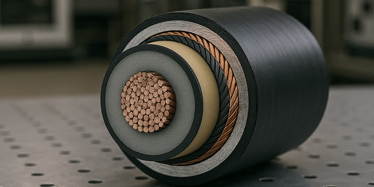
- Precision Conductor Compacting: Conductor strands are compressed with high filling factors ($> 90\%$) to minimize inter-strand air gaps, prevent water migration along the conductor core, and ensure uniform electrical stress distribution.
- Sheath Spark & Thickness Testing: Online high-voltage DC spark testers continuously inspect outer polyethylene and PVC sheaths during extrusion to verify 100% pinhole-free jacket integrity before shipment.
Whether supplying national electric utilities, renewable energy EPCs, or industrial substations across Africa, Latin America, Southeast Asia, and the Middle East, SiTong Cable provides full Type Test certification (KEMA / TUV / CNAS accredited) and material test reports (MTR) with every order.
8. Frequently Asked Questions (FAQ)
Q1: Why is DC hipoting strictly prohibited on service-aged XLPE underground cables?
DC hipoting applies a unidirectional electric field that causes space charges (accumulated trapped electrons and ions) to migrate and become locked in the polymeric crystalline structure of aged XLPE insulation. When the DC test voltage is removed and the cable is reconnected to the 50/60 Hz AC grid, the local electrical stress at the boundaries of existing water trees can exceed the dielectric breakdown threshold by a factor of 3 to 5, resulting in premature puncture shortly after returning to service. VLF (0.1 Hz) AC testing creates true bipolar alternating stress without space charge trapping.
Q2: What is the difference between Tan Delta Mean and Tan Delta Delta ($\Delta\text{TD}$)?
Mean Tan Delta measures the bulk, overall dielectric loss across the entire cable length at a specific test voltage (e.g., $1.0 U_0$), reflecting average moisture and oxidation. Tan Delta Delta ($\Delta\text{TD}$, or Tip-Up) represents the difference in dissipation factor between elevated voltage ($1.5 U_0$) and low voltage ($0.5 U_0$). A large $\Delta\text{TD}$ indicates severe non-linear dielectric loss, which is the primary hallmark of water trees polarizing and conducting under increased electrical stress.
Q3: How do engineers locate an underground cable fault when standard TDR shows no reflection?
Standard low-voltage TDR only reflects off metallic short circuits ($< 100\,\Omega$) or open circuits. Over 85% of underground cable failures are high-resistance flashover faults ($> 100\,\Omega$). Engineers use the Arc Reflection Method (ARM): a high-voltage surge generator discharges an impulse into the cable to create a momentary low-impedance electric arc at the fault location. The TDR transmits a pulse simultaneous with the arc, capturing a strong short-circuit reflection that pinpoints the fault distance.
Q4: Why is an outer sheath DC test (IEC 60229) recommended immediately after cable trench backfilling?
During cable pulling and trench backfilling, sharp rocks, improper bedding sand, or excessive mechanical dragging can gouge the outer protective jacket. If undetected, groundwater penetrates through the puncture, creating galvanic corrosion on the copper metallic screen and degrading the underlying semiconductor layer. Performing a 10 kV DC sheath integrity test immediately after backfill verifies jacket soundness before the site is paved or paved over, allowing inexpensive pinpoint repair via A-Frame methods.
Q5: What maximum Partial Discharge level is acceptable for newly installed MV cable circuits during commissioning?
Under IEC 60502-2 and IEEE 400.3, a factory-tested MV cable drum must exhibit partial discharge under 5 pC to 10 pC at $1.73 U_0$. In field commissioning of complete installed systems (which includes field-made terminations and joints), a PD magnitude of $\le 50\text{ pC}$ at $1.5 U_0$ is generally considered acceptable in field environments due to background noise constraints. Any discrete discharge exceeding $100\text{ pC}$ with localized PRPD clustering indicates installation error in a joint or termination that requires immediate remediation.
9. Conclusion & Engineering Support
Implementing modern diagnostic testing—VLF Tan Delta, Partial Discharge screening, DC sheath integrity testing, and advanced ARM fault location—transforms underground cable management from reactive fire-fighting into predictable, data-driven asset optimization.
By combining rigorous field commissioning standards with premium, factory-tested cable infrastructure from certified manufacturers, utility engineers can ensure 40+ years of uninterrupted underground power transmission.
👉 Browse our complete underground power cable systems range 👉 Explore our medium voltage power cables (6kV–35kV) 👉 Contact our technical engineering team for diagnostic support and project quotes
📬 Sales inquiries: sales@sitongcable.com | 📞 Phone: +86-371-69176007