VFD Motor Cable vs Standard Power Cable: Symmetrical 3+3 Grounding, Reflected Wave (dv/dt) Suppression & Common-Mode Current Engineering Guide
VFD Motor Cable vs Standard Power Cable: Symmetrical 3+3 Grounding, Reflected Wave (dv/dt) Suppression & Common-Mode Current Engineering Guide
Variable Frequency Drive (VFD) cable engineering addresses the severe electrical stresses generated by modern pulse-width modulated (PWM) inverter drives that cause catastrophic failures in standard industrial power cables.
In modern industrial automation, process manufacturing, mining, water treatment, and renewable energy facilities, Variable Frequency Drives (VFDs) paired with AC induction or permanent magnet synchronous motors (PMSM) are the standard for precision motor speed and torque control. However, the rapid evolution of power semiconductor technology—specifically the transition to high-speed Insulated Gate Bipolar Transistors (IGBTs) and Silicon Carbide (SiC) MOSFETs—has introduced severe high-frequency electrical phenomena. While standard low and medium voltage power cable systems perform reliably under pure 50 Hz/60 Hz sinusoidal excitation, they rapidly degrade when exposed to the steep-fronted voltage waveforms, high-frequency harmonics, and common-mode voltages characteristic of PWM inverters.
Engineers specifying drive systems must recognize that cable between the inverter and the motor operates not as a lumped-element conductor, but as a high-frequency transmission line. This technical guide examines the physics of PWM waveform propagation, compares symmetrical 3+3 grounding against conventional 4-core cable geometry, analyzes insulation dielectric requirements, evaluates high-frequency shielding mechanics, and provides a comprehensive specification framework in compliance with IEC 60034-18-41, IEC 60034-25, IEEE 1566, UL 1277 Type TC-ER, and ICEA S-95-658 / NEMA WC 70 standards.
1. The Physics of Modern PWM Inverters: Why Standard Cables Fail
A variable frequency drive rectifies 3-phase AC utility power into a smooth DC bus voltage ($V_{DC} \approx \sqrt{2} \times V_{LL}$, yielding approximately 650 V to 680 V DC for a 480 V system, and 930 V to 980 V DC for a 690 V system). The inverter stage synthesizes variable-frequency AC output by switching IGBTs on and off thousands of times per second using Pulse Width Modulation (PWM) at carrier frequencies typically between 2 kHz and 16 kHz.
       +-------------------------------------------------------------+
       |                  PWM INVERTER OUTPUT STAGE                  |
       |                                                             |
       |     +-------+          High dv/dt Switched Pulses           |
       |     | IGBT  |======+   Rise time tr: 50 ns - 100 ns         |
       |     | Bridge|      |   dv/dt: 5,000 - 12,000 V/µs           |
       |     +-------+      |                                        |
       +--------------------|----------------------------------------+
                            |
                     [ CABLE SYSTEM ]  <--- Operates as Distributed Transmission Line
                            |               Characteristic Impedance Zc: 60 - 120 Ω
                            v
       +-------------------------------------------------------------+
       |                     INDUCTION / PM MOTOR                    |
       |                                                             |
       |   Surge Impedance Zm: 1,000 - 5,000 Ω  (Impedance Mismatch) |
       |   Reflected Wave Peak Voltage: Vpeak >= 2 x Vdc             |
       |   Bearing Voltage & Common-Mode EDM Discharge               |
       +-------------------------------------------------------------+
The fundamental problem arises from the switching speed (rise time, $t_r$) of modern IGBTs: - Voltage Rise Time ($t_r$): 50 to 100 nanoseconds ($0.05\text{ to }0.1\ \mu\text{s}$). - Rate of Voltage Rise ($dv/dt$): $5,000\text{ to }12,000\text{ V}/\mu\text{s}$ (with modern SiC drives reaching up to $50,000\text{ V}/\mu\text{s}$). - Equivalent High-Frequency Spectrum: The Fourier transform of a pulse with a 50 ns rise time contains significant spectral energy extending from 100 kHz up to 30 MHz ($f_{max} \approx 1 / (\pi t_r)$).
When subjected to these high-frequency pulses, standard building wire (such as THHN/THWN) and standard unshielded 4-core PVC-insulated power cables suffer three major failure mechanisms.
2. The Three Destructive High-Frequency Inverter Phenomena
Phenomenon 1: Transmission Line Impedance Mismatch & Reflected Wave Overvoltage
The drive-cable-motor circuit behaves as a distributed-parameter transmission line. The surge (characteristic) impedance of an industrial shielded cable ($Z_c$) typically ranges between $60\ \Omega$ and $120\ \Omega$, whereas the surge impedance of an AC motor ($Z_m$) at high frequencies is significantly higher, typically between $1,000\ \Omega$ and $5,000\ \Omega$ (approaching an open circuit).
The voltage reflection coefficient at the motor terminals ($\Gamma_L$) is given by:
$$\Gamma_L = \frac{Z_m - Z_c}{Z_m + Z_c} \approx \frac{3000 - 80}{3000 + 80} \approx +0.95$$
Because $\Gamma_L \approx 1.0$, the incident voltage wave reflects with nearly identical polarity and magnitude, superimposing on the incoming waveform. The critical cable length ($L_{crit}$) beyond which full voltage doubling occurs at the motor terminals depends on the wave propagation velocity in the cable ($v \approx 150\text{ m}/\mu\text{s}$ to $180\text{ m}/\mu\text{s}$) and the pulse rise time ($t_r$):
$$L_{crit} = \frac{v \cdot t_r}{2}$$
For a standard drive with $t_r = 0.1\ \mu\text{s}$ and $v = 160\text{ m}/\mu\text{s}$, the critical distance is:
$$L_{crit} = \frac{160\text{ m}/\mu\text{s} \times 0.1\ \mu\text{s}}{2} = 8\text{ meters } (26.2\text{ ft})$$
If the cable run exceeds just 8 meters, peak voltages at the motor terminals reach $2.0 \times V_{DC}$ to $2.5 \times V_{DC}$ (due to cable ringing and multiple reflections). On a 480 V AC nominal system ($V_{DC} \approx 678\text{ V}$), peak transient voltages reach $1,400\text{ V to }1,700\text{ V}$. On a 690 V AC mining or marine system ($V_{DC} \approx 975\text{ V}$), transient spikes exceed $2,400\text{ V}$. Standard PVC/Nylon insulation rated for 600 V rapidly experiences partial discharge (corona) breakdown, micro-arcing, and thermal degradation.
       VOLTAGE REFLECTED WAVE PHENOMENON AT MOTOR TERMINALS
       ----------------------------------------------------
       Voltage (V)
         ^
  2.2x Vdc |          /\      /\
           |         /  \    /  \      <-- Peak Voltage Ringing Spikes
   2.0x Vdc|--------/----\--/----\-----------------------------
           |       /      \/      \
           |      /                \
     1.0x Vdc|-----+                  +-------------------------  (Nominal DC Bus)
           |     |
           |     | <--- Rise time tr (50 - 100 ns)
           0-----+---------------------------------------------> Time (t)
Phenomenon 2: Common-Mode Voltage ($V_{cm}$) and Bearing EDM Current Destruction
In a balanced 3-phase sinusoidal power supply, the instantaneous sum of the three phase-to-ground voltages is always zero:
$$V_{a}(t) + V_{b}(t) + V_{c}(t) = 0$$
In a 3-phase PWM inverter, the DC bus is switched to discrete states ($+V_{DC}/2$ or $-V_{DC}/2$). At any instant, the instantaneous sum is never zero. The resulting common-mode voltage ($V_{cm}$) is defined as:
$$V_{cm} = \frac{V_a + V_b + V_c}{3}$$
$V_{cm}$ fluctuates continuously between $\pm V_{DC}/6$ and $\pm V_{DC}/2$ at the carrier switching frequency. This pulsating common-mode voltage couples capacitively through the cable insulation to the cable tray and motor frame. More critically, inside the motor, $V_{cm}$ couples across the stator-to-rotor air gap capacitance ($C_{sr}$), charging the motor shaft:
$$V_{shaft} = V_{cm} \times \left( \frac{C_{sr}}{C_{sr} + C_{b}} \right)$$
Where $C_b$ is the bearing oil film capacitance. When $V_{shaft}$ exceeds the dielectric breakdown threshold of the thin lubricating oil film (typically 15 V to 30 V), an electric arc discharges directly through the steel balls and bearing raceway. This Electrical Discharge Machining (EDM) creates micro-craters, microscopic pitting, and characteristic "fluting" washboard patterns on the bearing races, leading to catastrophic bearing seizure within months of commissioning.
Phenomenon 3: High-Frequency Electromagnetic Interference (EMI / RFI)
High $dv/dt$ and $di/dt$ transitions generate severe electromagnetic fields across radio-frequency bands (150 kHz to 30 MHz for conducted emissions, 30 MHz to 1 GHz for radiated emissions). When unshielded cables are installed in shared industrial cable trays or conduits alongside sensitive analog sensor loops, 4–20 mA transmitters, RS-485 communication lines, or industrial control cable circuits, capacitive and inductive cross-talk induces severe control signal corruption and phantom PLC trips.
3. Geometric Conductor Architecture: Symmetrical 3+3 vs Asymmetrical 4-Core
The internal cross-sectional geometry of a motor power cable directly governs its high-frequency common-mode electromagnetic performance.
+-----------------------------------------------------------------------------------+
|                           CROSS-SECTIONAL COMPARISON                              |
|                                                                                   |
|     STANDARD 4-CORE CABLE (ASYMMETRICAL)         VFD 3+3 CABLE (SYMMETRICAL)      |
|                                                                                   |
|                   [ Phase A ]                                [ Phase A ]          |
|                   /         \                                /   |   \            |
|                  /           \                             (g1)  |   (g3)         |
|                 /             \                            /     |     \          |
|          [ Phase B ] ===== [ Ground ]               [ Phase B ] === [ Phase C ]   |
|                 \             /                            \     |     /          |
|                  \           /                             (g2)  |    /           |
|                   [ Phase C ]                                \   |   /            |
|                                                                                   |
|     * Unequal ground-to-phase spacing              * 3 split ground conductors    |
|     * Net induced magnetic flux != 0                 interspaced at 120°          |
|     * Massive circulating ground currents          * Zero net induced ground flux |
|     * Uncontrolled bearing return path             * Controlled low-Z return path |
+-----------------------------------------------------------------------------------+
Why Standard 4-Core Cables Fail
A standard 4-core cable consists of three insulated phase conductors (A, B, C) and a single full-sized ground conductor (G) cabled together in a planetary twist. 1. Geometric Asymmetry: The distance from the single ground conductor to Phase A and Phase C is significantly shorter than the distance to Phase B. 2. Induced Ground Currents: Because the spatial magnetic field around the three phase conductors does not cancel symmetrically at the location of the single ground wire, a net longitudinal electromotive force (EMF) is induced directly onto the ground wire. 3. Stray Return Currents: The high-frequency common-mode return current seeks uncontrolled alternate paths back to the drive—traveling through building structural steel, motor foundations, pipework, and motor bearings.
The Engineered Symmetrical 3+3 Design
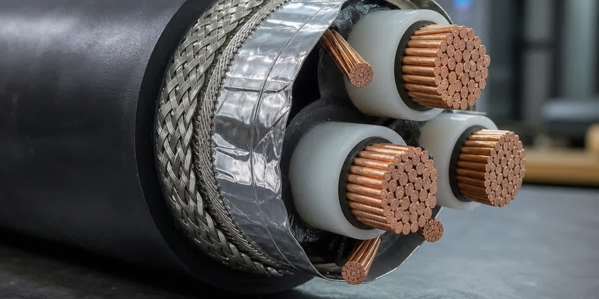
To achieve total electromagnetic balance, dedicated VFD cable utilizes three segmented bare or insulated ground conductors positioned symmetrically in the interstitial valleys between the three main insulated phase conductors. - $120^\circ$ Geometric Symmetry: Each ground wire is positioned equidistant from two phase conductors and exactly $120^\circ$ apart from the other ground wires. - Zero Net Induced Flux: The high-frequency magnetic vector sum induced in the three parallel ground wires sums to zero ($\sum \vec{B}{induced} = 0$). - Equal Inter-Conductor Capacitance: Mutual capacitance from each phase to ground ($C$) is identical, eliminating phase-to-ground capacitive imbalance. - } = C_{bg} = C_{cgDirect Low-Impedance Return: The high-frequency common-mode current flows symmetrically back to the drive through the three ground wires and surrounding shield, bypassing motor bearings entirely.
4. Dielectric & Insulation Engineering: XLPE vs PVC / THHN
The choice of primary insulation material is the most critical factor determining cable lifespan under inverter-duty stress.
| Performance Parameter | Cross-Linked Polyethylene (XLPE) | Standard PVC / Nylon (THHN/THWN) | Engineering Significance |
|---|---|---|---|
| Dielectric Constant ($\epsilon_r$ at 1 MHz) | $2.25 - 2.35$ (Very Low) | $4.5 - 8.0$ (High & Variable) | Lower capacitance minimizes charging current and losses. |
| Dissipation Factor ($\tan \delta$ at 1 MHz) | $< 0.0004$ (Extremely Low) | $0.050 - 0.120$ (Very High) | Minimizes high-frequency dielectric heating inside the cable. |
| Dielectric Breakdown Strength | $> 30\text{ kV/mm}$ | $15 - 20\text{ kV/mm}$ | High impulse withstand against $2.5 \times V_{DC}$ reflected waves. |
| Corona / Partial Discharge Inception | $> 2,000\text{ V Peak}$ | $600 - 800\text{ V Peak}$ | Prevents micro-void ionization and electrical treeing. |
| Continuous Operating Temperature | $90^\circ\text{C}$ (Dry / Wet) | $75^\circ\text{C} / 90^\circ\text{C}$ | Thermoset material resists thermal softening under overcurrent. |
| Short-Circuit Temperature Rating | $250^\circ\text{C}$ | $150^\circ\text{C} / 160^\circ\text{C}$ | Superior resilience during downstream phase-to-ground faults. |
| Moisture Absorption Resistance | $< 0.01\%$ | $0.5 - 1.5\%$ | Maintains dielectric integrity in wet conduit/tray installations. |
Capacitive Charging Current Calculation
The high dielectric constant of PVC creates high mutual capacitance ($C_{mutual}$), which draws significant high-frequency capacitive charging current ($I_c$) from the drive output stage:
$$I_c = C_{cable} \times \frac{dv}{dt}$$
For example, a 100-meter run of PVC cable with a mutual capacitance of $280\text{ pF/m}$ ($C_{total} = 28\text{ nF}$) subjected to a $dv/dt$ of $8,000\text{ V}/\mu\text{s}$ draws a peak reactive pulse current of:
$$I_{peak} = 28\text{ nF} \times 8,000\text{ V}/\mu\text{s} = 224\text{ Amperes}$$
This parasitic current pulse spikes through the drive IGBTs during every switching transition, generating excessive inverter heat, causing false overcurrent drive trips, and reducing system efficiency. By comparison, XLPE insulation reduces cable capacitance to $80 - 110\text{ pF/m}$, cutting parasitic capacitive charging currents by over 60%.
5. High-Frequency Shielding Architecture & Transfer Impedance ($Z_t$)
Effective containment of high-frequency electromagnetic fields requires a specialized dual-shielding or continuous metallic armor system engineered for low Surface Transfer Impedance ($Z_t$).
+-----------------------------------------------------------------------------------+
|                        DUAL-LAYER HIGH-PERFORMANCE VFD SHIELD                     |
|                                                                                   |
|   [ Heavy-Duty Industrial PVC/CPE Outer Jacket (UV & Oil Resistant) ]             |
|     +-- [ Layer 2: Tinned Copper Braid Shield (>= 85% Optical Coverage) ]         |
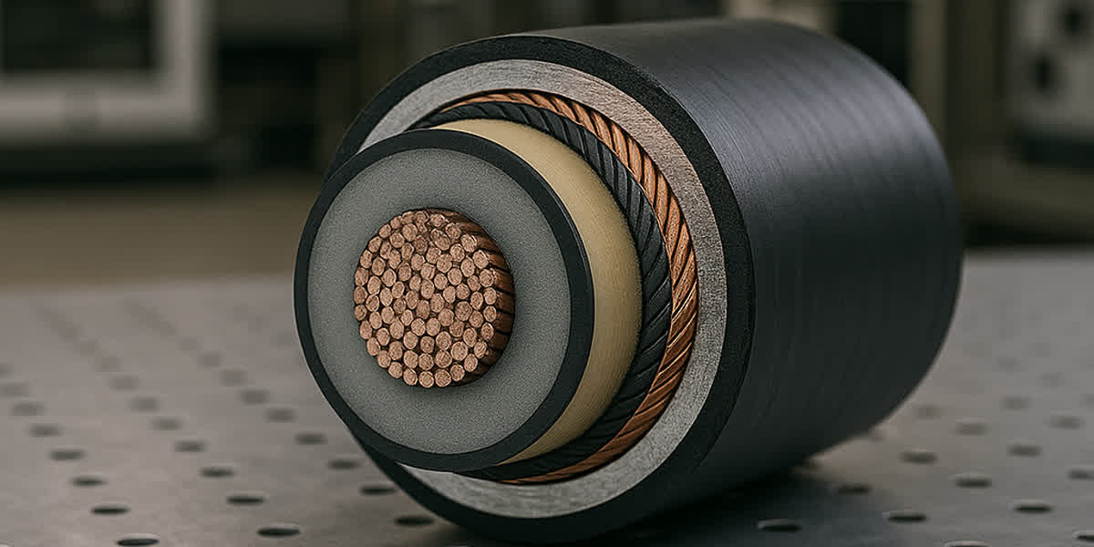
|           +-- [ Layer 1: 100% Coverage Aluminum/Polyester Tape (Foil Bonded) ]    |
|                 +-- [ Extruded Core Assembly: 3 XLPE Phases + 3 Symmetrical GND ] |
|                                                                                   |
|   * Aluminum Foil (100% Coverage): Superior high-frequency screening (> 10 MHz)  |
|   * Tinned Copper Braid (>= 85%): Superior low/mid-frequency shielding (< 10 MHz) |
|     and robust low-resistance fault current path (< 1 Ω/km)                      |
+-----------------------------------------------------------------------------------+
Surface Transfer Impedance ($Z_t$)
Transfer impedance is the standard figure of merit (defined in IEC 62153-4-3) that measures shield effectiveness:
$$Z_t = \frac{1}{I_{shield}} \times \left( \frac{dV_{inner}}{dx} \right)\quad [\Omega/\text{m}]$$
A lower $Z_t$ indicates superior shield screening performance. - Standard Steel Wire Armored (SWA) Cables: SWA provides excellent mechanical crushing protection, but the magnetic permeability and high contact resistance of galvanized steel wires cause transfer impedance to rise sharply above 100 kHz ($Z_t > 500\text{ m}\Omega/\text{m}$ at 10 MHz), making standard SWA ineffective as an RF shield. - Dual Foil + Tinned Copper Braid Shield: The combination of 100% aluminum/polyester tape and high-density ($\ge 85\%$) tinned copper braid provides an ultra-low transfer impedance across the entire frequency spectrum: - $10\text{ kHz to }1\text{ MHz}$: Governed by the low DC resistance of the heavy tinned copper braid ($Z_t < 5\text{ m}\Omega/\text{m}$). - $1\text{ MHz to }30\text{ MHz}$: Skin effect and foil conduction maintain shielding efficiency ($Z_t < 10\text{ m}\Omega/\text{m}$). - $> 30\text{ MHz}$: Continuous 100% foil wrap eliminates high-frequency electromagnetic aperture leakage.
For heavy industrial, hazardous (Class I Div 1 / Zone 1), and offshore environments, Continuously Corrugated Welded (CCW) Aluminum Armor (Type MC-HL) provides a completely impervious, seamless 360-degree metallic conduit barrier offering near-zero transfer impedance and maximum mechanical protection.
6. Technical Specifications & Engineering Sizing Matrix
The following matrix provides comprehensive mechanical and electrical specifications for SiTong Cable's premium 600V / 1000V / 2000V Symmetrical 3+3 XLPE Insulated VFD Cable product line manufactured to UL 1277 Type TC-ER, IEEE 1566, and IEC 60502-1.
| Phase Size (AWG / kcmil) | Phase Conductor Area ($mm^2$) | Stranding Class (ASTM B8/B174) | Symmetrical Ground Wires ($3 \times mm^2$) | Insulation Thickness (XLPE mm) | Nominal Overall Diameter (mm) | Approx. Net Weight (kg/km) | Ampacity at 90°C In Tray (A) | Max DC Resistance at 20°C ($\Omega/km$) |
|---|---|---|---|---|---|---|---|---|
| 14 AWG | 2.08 | Class C (19 str) | $3 \times 0.52$ (20 AWG) | 1.14 | 14.8 | 315 | 25 | 8.86 |
| 12 AWG | 3.31 | Class C (19 str) | $3 \times 0.82$ (18 AWG) | 1.14 | 16.2 | 395 | 30 | 5.58 |
| 10 AWG | 5.26 | Class C (19 str) | $3 \times 1.31$ (16 AWG) | 1.14 | 17.8 | 490 | 40 | 3.51 |
| 8 AWG | 8.37 | Class B (19 str) | $3 \times 2.08$ (14 AWG) | 1.52 | 21.5 | 730 | 55 | 2.21 |
| 6 AWG | 13.30 | Class B (19 str) | $3 \times 2.08$ (14 AWG) | 1.52 | 23.8 | 960 | 75 | 1.39 |
| 4 AWG | 21.15 | Class B (19 str) | $3 \times 3.31$ (12 AWG) | 1.52 | 26.5 | 1,320 | 95 | 0.875 |
| 2 AWG | 33.62 | Class B (19 str) | $3 \times 5.26$ (10 AWG) | 1.52 | 29.8 | 1,840 | 130 | 0.550 |
| 1/0 AWG | 53.49 | Class B (19 str) | $3 \times 8.37$ (8 AWG) | 2.03 | 36.2 | 2,750 | 170 | 0.345 |
| 2/0 AWG | 67.43 | Class B (19 str) | $3 \times 8.37$ (8 AWG) | 2.03 | 38.6 | 3,310 | 195 | 0.274 |
| 3/0 AWG | 85.01 | Class B (19 str) | $3 \times 13.3$ (6 AWG) | 2.03 | 42.4 | 4,020 | 225 | 0.217 |
| 4/0 AWG | 107.2 | Class B (19 str) | $3 \times 13.3$ (6 AWG) | 2.03 | 46.5 | 4,950 | 260 | 0.172 |
| 250 kcmil | 126.7 | Class B (37 str) | $3 \times 13.3$ (6 AWG) | 2.29 | 51.2 | 5,880 | 290 | 0.146 |
| 350 kcmil | 177.3 | Class B (37 str) | $3 \times 21.2$ (4 AWG) | 2.29 | 58.0 | 7,850 | 350 | 0.104 |
| 500 kcmil | 253.4 | Class B (37 str) | $3 \times 21.2$ (4 AWG) | 2.29 | 66.8 | 10,800 | 430 | 0.073 |
Note: Ampacities calculated according to NEC Table 310.16 at $90^\circ\text{C}$ conductor temperature, $30^\circ\text{C}$ ambient. When connecting to motor and drive terminals, verify compatibility with certified cable lugs and compression terminals rated for high-strand flexible conductors.
7. Output Filter Selection vs Cable Length Guidelines
When engineering inverter cable runs, the combination of cable length, drive carrier frequency, and motor insulation class dictates whether output conditioning filters are mandatory.
       CABLE LENGTH AND FILTER SELECTION DECISION TREE
       -----------------------------------------------
       Cable Run Length:

       0 to 15 meters (0 to 50 ft):
       +---> Standard VFD Cable (Symmetrical 3+3, Dual Shield). No output reactor required.

       15 to 100 meters (50 to 330 ft):
       +---> Standard VFD Cable + 3% or 5% AC Output Line Reactor (Load Reactor).
             Smooths current spikes, reduces dv/dt to < 1,000 V/µs.

       100 to 300 meters (330 to 1,000 ft):
       +---> Standard VFD Cable + dv/dt Filter (RC Snubber / Choke).
             Limits peak motor terminal voltage to <= 120% Vdc; limits dv/dt to < 200 V/µs.

       > 300 meters (> 1,000 ft):
       +---> Standard VFD Cable + Sine Wave Output Filter (LC Low-Pass Filter).
             Reconstructs pure sinusoidal waveform (THD < 5%), eliminates all PWM reflections.
| Output Filter Type | Operating Principle | Peak Voltage at Motor ($V_{peak}$) | Voltage Rise Time ($t_r$) | Recommended Max Cable Length | Key Application Scenario |
|---|---|---|---|---|---|
| No Filter | Direct PWM drive output | $2.0 - 2.5 \times V_{DC}$ | $50 - 100\text{ ns}$ | $< 15\text{ m } (50\text{ ft})$ | Close-coupled motor installations |
| Load Reactor (3% or 5% Line Choke) | Series inductive impedance ($\omega L$) | $1.8 - 2.1 \times V_{DC}$ | $200 - 500\text{ ns}$ | $15 - 100\text{ m } (50 - 330\text{ ft})$ | General factory floor motor feeders |
| dv/dt Filter (Snubber Network) | Inductor + damping resistor network | $\le 1.25 \times V_{DC}$ | $1.0 - 2.0\ \mu\text{s}$ | $100 - 300\text{ m } (330 - 1,000\text{ ft})$ | Deep well pumps, remote cooling towers |
| Sine Wave Output Filter | 3-phase LC low-pass filter | $1.0 \times V_{LL}\text{ (Sinusoidal)}$ | Pure Sine Wave | Up to $1,000\text{ m } (3,300\text{ ft})$ | Submersible pumps, long mining conveyers |
8. Installation, 360° EMC Gland Termination & Grounding Best Practices
The electrical advantages of symmetrical 3+3 VFD cable can be completely compromised if terminated with improper field practices.
       CORRECT 360-DEGREE EMC GLAND TERMINATION PRACTICE
       -------------------------------------------------
       [ VFD Cable Outer Jacket ]
          |
          +---> Stripped back precisely to expose braid
          |
       [ 360° Metal EMC Contact Spring / Cone Inside Gland Body ]
          |     * 100% circumferential metallic contact around exposed tinned copper braid
          |     * Zero pigtail inductance (Zero pigtail wire!)
          |
       [ Heavy Brass Nickel-Plated Gland Body & Locknut ]
          |     * Screwed directly into metal drive enclosure / motor terminal box
          |     * Star locknut digs through paint into bare enclosure metal
          v
       [ Low-Impedance High-Frequency Chassis Ground ]
Critical Field Installation Rules:
- Never Make "Pigtail" Ground Connections: Twisting the shield braid into a 10 cm wire pigtail introduces approximately $10\text{ nH/cm}$ of parasitic inductance. At 10 MHz switching transients: $$X_L = 2\pi \times 10^7\text{ Hz} \times 100\text{ nH} \approx 6.28\ \Omega$$ A $6.28\ \Omega$ impedance at RF creates a high-voltage drop across the pigtail, destroying shield effectiveness and radiating noise.
- Mandatory $360^\circ$ EMC Glands: Use brass nickel-plated EMC cable glands equipped with internal circumferential spring contacts that clamp directly onto the exposed tinned copper braid shield. Secure all fittings using robust cable hardware and accessories to maintain ground continuity.
- Ground Both Ends of the Shield: Terminate the cable shield at both the drive chassis ground and the motor terminal ground box. This creates a low-impedance Faraday cage and provides a dedicated return path for high-frequency common-mode currents.
- Physical Separation Distances in Trays: Maintain a minimum physical clearance of at least 300 mm (12 inches) between VFD motor power cables and sensitive instrumentation, encoder, or PLC signal wiring. If cables must cross, cross at a right angle ($90^\circ$).
9. SiTong Cable Manufacturing Excellence & Quality Verification
As a premier global cable manufacturer, Zhengzhou Sitong Cable Co., Ltd. (SiTong Cable) engineers and manufactures industrial-grade VFD inverter cables designed for severe duty in mining, oil & gas, marine, chemical, and automated manufacturing facilities.
Rigorous Manufacturing Processes:
- High-Purity Electrolytic Copper: Phase and ground conductors drawn from $99.99\%$ oxygen-free electrolytic copper (OFEC) annealed to ASTM B3 and B174 for maximum electrical conductivity and superior torsional flexibility.
- Triple-Extrusion Continuous Curing Line: Cross-linked polyethylene (XLPE) extruded with precise concentricity control ($\ge 95\%$) and computer-monitored wall thickness to prevent local dielectric stress concentrations.
- High-Coverage Braid Machinery: 24-carrier and 36-carrier high-speed braiding machines ensure a consistent $\ge 85\%$ optical coverage tinned copper shield layered over a bonded $100\%$ aluminum/polyester electrostatic tape.
- Severe Environmental Jacketing: Heavy-duty thermoplastic or thermoset outer jackets formulated for extreme resistance to ultraviolet sunlight (UL 1581), industrial oils, chemical splash, and direct burial ($90^\circ\text{C}$ wet/dry).
Comprehensive Factory Acceptance Testing (FAT):
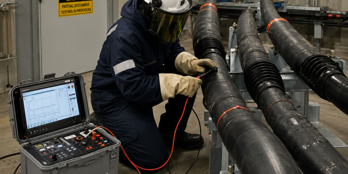
Every production drum undergoes 100% factory routine testing before dispatch: - Spark Testing: 100% inline spark testing at $10\text{ kV}$ AC. - AC Withstand Voltage Test: $3.5\text{ kV}$ AC for 5 minutes between phase conductors and shield without dielectric breakdown. - Partial Discharge (PD) Verification: Routine PD testing with background noise $< 2\text{ pC}$, ensuring inception voltage well exceeds $2,500\text{ V}$ peak. - Transfer Impedance Testing: Validated to IEC 62153-4-3 up to 100 MHz.
10. Frequently Asked Questions (FAQ)
Q1: Can I use standard 4-core PVC or THHN building wire for a VFD motor if it is run inside rigid metallic steel conduit?
No. While rigid steel conduit provides some magnetic shielding at power frequencies, it does not solve the internal high-frequency failure mechanisms. Standard THHN/PVC insulation has a high dielectric constant ($\epsilon_r > 5$), high dielectric loss ($\tan \delta$), and low corona resistance. The rapid $dv/dt$ pulses from the inverter cause partial discharge inside the PVC insulation, resulting in premature insulation puncture. Furthermore, the asymmetrical geometry of a standard 4-core wire inside conduit still generates common-mode bearing currents that destroy motor bearings.
Q2: Why does a symmetrical 3+3 ground design prevent motor bearing failures?
In a symmetrical 3+3 cable, three ground wires are placed $120^\circ$ apart in the outer valleys between the phase conductors. Because the spatial distances from each phase conductor to the ground network are identical, the net magnetic field induced on the ground system is zero. The high-frequency common-mode current induced on the motor shaft is provided a balanced, ultra-low impedance return path back through the three ground wires and the shield, preventing common-mode voltage buildup across the motor bearing oil film and eliminating Electrical Discharge Machining (EDM) fluting.
Q3: What is the maximum distance I can run a VFD cable without installing an output filter?
For standard 480 V NEMA Premium or IEC inverter-duty motors (with insulation rated for $1,600\text{ V}$ peak), the critical threshold without filters is typically 15 meters (50 feet). Beyond 15 meters, reflected wave voltage doubling exceeds the motor insulation withstand rating. Installing a 3% or 5% load reactor extends allowable distance up to 100 meters (330 ft). For runs between 100 and 300 meters, a $dv/dt$ filter is required; beyond 300 meters, a sine wave filter is mandatory.
Q4: Should the VFD cable shield be grounded at one end or both ends?
The VFD cable shield must be grounded at both ends (at the drive enclosure chassis and at the motor terminal box ground lug). High-frequency common-mode return currents must flow back to the drive DC bus filter. Grounding only one end creates an open-circuit RF antenna that allows high-frequency voltages to build up on the ungrounded end, radiating intense electromagnetic interference (EMI) and forcing bearing current to ground through the motor foundation.
Q5: What is the difference between 600V, 1000V, and 2000V rated VFD cables?
The voltage rating reflects the insulation wall thickness and dielectric impulse withstand capability. On 480V systems, 600V/1000V XLPE VFD cables provide ample protection against $1,600\text{ V}$ peak reflected waves. On 575V, 690V, or medium-voltage inverter drives, or when long cable runs create transient spikes exceeding $2,000\text{ V}$, 2000V rated VFD cable with heavy-wall XLPE insulation is essential to guarantee a 30+ year service life without dielectric breakdown.
11. Engineering Recommendations & Product Selection Summary
Selecting the proper motor feeder cable is a fundamental engineering decision that determines the operational reliability, motor longevity, and electromagnetic compatibility (EMC) of modern automated industrial plants.
       SUMMARY OF VFD CABLE SPECIFICATION CRITERIA
       -------------------------------------------
       [ Conductor Geometry ]   ==> Symmetrical 3 Phase + 3 Interstitial Grounds (120° Layout)
       [ Primary Insulation ]  ==> Thermoset XLPE (Dielectric Constant <= 2.35, Corona Resistant)
       [ Shielding System ]    ==> 100% Aluminum Foil + >= 85% Tinned Copper Braid (Dual Shield)
       [ Voltage Rating ]      ==> 1000V / 2000V (UL 1277 Type TC-ER, IEEE 1566, IEC 60502-1)
       [ Termination Method ]  ==> 360° Metallic EMC Cable Glands (Zero Pigtails)
👉 Browse our complete Power Cable product range
👉 Explore our Industrial Control Cable solutions
👉 Select Certified Cable Lugs & Compression Terminals
👉 Contact SiTong Cable Technical Engineering Team for Custom VFD Cable Sizing
📬 Sales inquiries: sales@sitongcable.com | 📞 Phone / WhatsApp: +86-371-69176007