Overhead Line Fittings & Hardware Engineering Guide: Tension Clamps, Suspension Hardware, Mechanical Safety Factors and Conductor Fatigue Protection
Overhead Line Fittings & Hardware Engineering Guide: Tension Clamps, Suspension Hardware, Mechanical Safety Factors and Conductor Fatigue Protection
Overhead transmission and distribution lines represent intricate structural-mechanical networks where bare conductors, insulated cables, and optical ground wires must withstand severe mechanical tension, dynamic wind excitation, thermal cycling, and environmental corrosion over operational lifespans exceeding 40 years. While electrical utilities and EPC contractors allocate substantial resources to conductor sizing, sag-tension calculations, and tower footing resistances, field failure investigations consistently reveal that the electrical and mechanical integrity of the entire grid rests heavily on its connection interfaces: overhead line fittings and pole line hardware.
From securing heavy steel-reinforced conductors on high-tension dead-end river crossings to absorbing high-frequency aeolian vibration on tangent suspension towers, hardware assemblies serve as the primary mechanical load path and electrical bonding mechanism. Applying improper clamp torque, selecting mismatched metallurgy, or underestimating dynamic stress concentrations inevitably leads to fatigue-induced conductor strand breakage, severe galvanic corrosion, insulator string uncoupling, and catastrophic line drops.
As an international power transmission manufacturer and turnkey grid partner, Zhengzhou Sitong Cable Co., Ltd. (SiTong Cable) engineers and supplies high-grade overhead conductors alongside type-tested hardware systems certified to IEC 61284, ANSI C119.4, BS 3288, and EN 50341. This comprehensive technical guide provides electrical engineers, line designers, and procurement managers with an in-depth analysis of hardware classification, gripping mechanics, holding strength ratings, metallurgy selection, safety factors, and failure mitigation strategies.
1. Classification & Functional Anatomy of Overhead Line Hardware
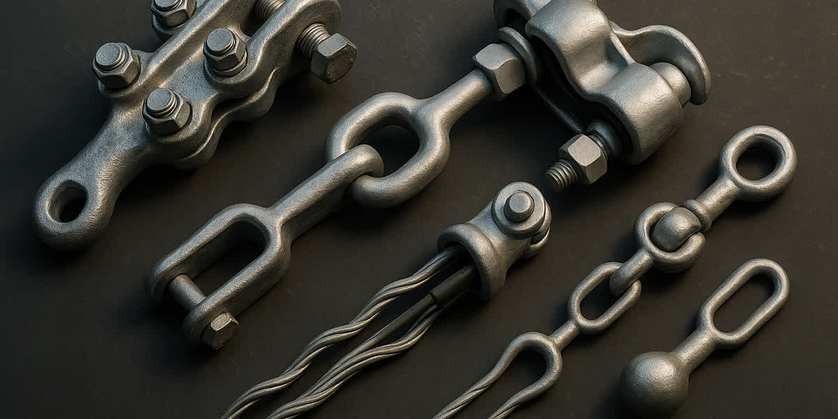
Overhead line hardware encompasses a specialized family of forged, cast, stamped, and helically formed metallic components engineered to suspend, anchor, connect, and protect conductors and insulators. International standards categorize line hardware into five primary functional groups based on their mechanical and electrical duties:
Overhead Line Fittings Classification (IEC 61284 / BS 3288)
 ├── 1. Tension / Dead-End Fittings
 │     ├── Bolted Strain Clamps (Quadrant / NLD Type)
 │     ├── Compression Dead-End Assemblies (Two-Sleeve / Hexagonal Die)
 │     └── Helical Preformed Dead-End Grips
 ├── 2. Suspension Fittings
 │     ├── Trunnion / Envelope Cast Aluminum Clamps
 │     ├── Armoured AGS (Armour Grip Suspension with Neoprene Cushion)
 │     └── Tandem / Double Suspension Assemblies for River Crossings
 ├── 3. Linkage & Connection Fittings
 │     ├── Ball Eye & Socket Eye Fittings (IEC 60120 Pin Coupling)
 │     ├── Clevis-Tongue & Shackle Couplings
 │     └── Yoke Plates (Triangle, Rectangular, Hexagonal for Bundled Conductors)
 ├── 4. Protective & Vibration Damping Hardware
 │     ├── Stockbridge Dampers & Multi-Frequency Dampers
 │     ├── Helical Armour Rods & Line Guards
 │     └── Corona Rings & Grading Rings (≥220 kV Lines)
 └── 5. Electrical Jointing & Conductor Connectors
       ├── Mid-Span Full-Tension Compression Joints
       ├── Parallel Groove (PG) Clamps & Bimetallic Transition Connectors
       └── Insulation Piercing Connectors (IPC for LV ABC Lines)
In heavy-duty power grids, hardware assemblies must function synergistically with standard bare conductors. For instance, high-capacity transmission spans utilizing our ACSR conductor range or all-aluminum-alloy AAAC conductor line depend on precision-matched clamping geometries to transfer massive tensile loads without crushing the outer aluminum stranding layers.
2. Tension and Dead-End Clamps: Mechanics & Holding Strength
Tension assemblies (dead-end or strain hardware) anchor conductors at terminal substations, angle towers (deflection angle >15°), and tension section breaks. They must carry 100% of the conductor's working mechanical tension under extreme weather conditions (NESC Heavy loading: combined wind pressure and radial ice accretion).
2.1 Bolted Strain Clamps (Quadrant / NLD Series)
Bolted quadrant strain clamps consist of a high-strength body (cast ductile iron for steel conductors or high-purity aluminum alloy for all-aluminum lines) with curved conductor grooves and high-tensile U-bolts:
- Holding Strength: Bolted clamps typically develop ≥65% to 85% of the Rated Tensile Strength (RTS) of the conductor. They rely purely on mechanical friction generated by normal bolt clamping force ($F_N$) acting across the contact arc length: $$T_{hold} = \mu \cdot \sum F_N \cdot e^{\mu \theta}$$ Where $\mu$ is the friction coefficient between conductor and clamp body, and $\theta$ is the contact wrap angle.
- Application: Medium-voltage distribution networks (11 kV–35 kV) and low-tension sub-transmission spans. Bolted clamps allow conductor tension adjustment and dismantling during maintenance without severing the conductor.
- Torque Sensitivity: Proper calibrated torque (e.g., 45 Nm for M12 bolts, 75 Nm for M16 bolts) is paramount. Under-torquing leads to conductor slip under storm winds, while over-torquing crushes the conductor's outer layer, causing premature fatigue failure under cyclic aeolian vibration.
2.2 Compression Dead-End Assemblies
For high-voltage transmission lines (66 kV up to 500 kV), bolted clamps cannot provide sufficient holding efficiency or corona performance. Compression dead-end assemblies achieve ≥95% of the conductor RTS, conforming to IEC 61284 Class 1:
- Two-Sleeve System for ACSR:
- Inner Steel Sleeve: High-strength forged structural steel sleeve, hot-dip galvanized, filled with anti-friction compound, compressed directly onto the galvanized steel core wire using a hydraulic press and hexagonal dies.
- Outer Aluminum Sleeve: Extruded EC-grade aluminum sleeve, pre-injected with conductive oxide-inhibiting joint compound (silicon carbide grit in synthetic grease). When compressed over the outer aluminum strands and jumper palm, it provides a low-resistance electrical bridge while transferring residual mechanical tension.
- Monobloc Compression for All-Aluminum/Alloy Conductors:
- A single high-conductivity aluminum sleeve compressed over AAC conductors or ACAR conductors.
2.3 Helical Preformed Dead-End Grips
Manufactured from high-tensile aluminum-clad steel (ACS) or galvanized steel wire strands conforming to ASTM A475 and BS 183, preformed helical dead-ends distribute radial gripping force uniformly over a long contact length (often 1.2 to 2.0 meters):
- No Bolt or Compression Stress Concentrations: Eliminates crushing forces, making it ideal for optical ground wire (OPGW cable range), high-strength guy wires using galvanized steel wire strands, and distribution lines.
- Holding Capability: Consistently achieves 100% of conductor RTS while preserving fiber optical attenuation in OPGW cables.
3. Suspension Hardware: Conductor Support and Dynamic Fatigue Protection
Suspension clamps support the vertical conductor weight and transverse wind load on tangent (straight-line) towers. Unlike tension clamps, suspension hardware must allow the conductor to flex naturally without introducing sharp bending moments at the suspension mouth.
3.1 Fixed Trunnion vs. Armour Grip Suspension (AGS)
| Technical Feature | Standard Trunnion / Envelope Suspension Clamp | Armour Grip Suspension (AGS) Assembly |
|---|---|---|
| Primary Material | A356 Cast Aluminum Alloy (Body) + Galvanized Steel Keeper | Forged Aluminum Alloy Housing + Neoprene Elastomer Insert + Helical Rods |
| Conductor Contact Interface | Direct metal-to-metal contact with conductor outer strands | Resilient elastomer cushion distributing radial clamping force |
| Static Bending Stress Reduction | Minimal; sharp inflection angle at clamp lip | Reduces dynamic bending stress by 40%–60% at clamp mouth |
| Slip Load (IEC 61284) | 10% to 25% of conductor RTS | 15% to 20% of conductor RTS (controlled slip during unbalanced pull) |
| Aeolian Vibration Fatigue Life | Moderate; susceptible to fretting fatigue under un-damped winds | Superior (>4x fatigue life); eliminates metal-to-metal fretting wear |
| Recommended Voltage Level | LV to MV Distribution (1 kV – 69 kV) | High Voltage & EHV Transmission (110 kV – 500 kV), Long Spans, River Crossings |
| Compatible Hardware Category | Pole line brackets via fittings & hardware line | Heavy-duty insulator strings and multi-bundle yoke plates |
3.2 Mechanical Fatigue & Fretting Corrosion Mitigation
Under steady, low-velocity laminar cross-winds (1 to 7 m/s), overhead lines experience vortex-induced high-frequency aeolian vibration (5 to 50 Hz). The point of maximum dynamic stress concentration occurs precisely at the mouth of the suspension clamp.
Without protective helical armour rods or resilient neoprene cushions, microscopic relative slip occurs between conductor strands and the clamp surface. This micro-motion breaks down the protective aluminum oxide film, producing powdery black aluminum debris (fretting corrosion). Within 3 to 10 years of installation, fatigue cracks propagate through the outer strands, resulting in broken conductor strands and phase separation.
4. Mechanical Safety Factors, Proof Testing & Environmental Resilience
Transmission line engineering mandates rigorous mechanical safety factors to prevent structural collapse under extreme environmental events (ice storms, microburst gusts, and broken-conductor shock loads).
4.1 Safety Factor Guidelines (IEC 60826 & EN 50341)
$$SF = \frac{\text{Minimum Failing Load (MFL)}}{\text{Maximum Working Tension (MWT)}}$$
- Tension Clamps & Dead-End Hardware: Safety Factor $\ge 2.5$ under everyday average conditions (Everyday Stress: 18%–22% RTS), and $\ge 1.5$ under maximum design storm/ice load combination.
- Suspension Clamps & Supporting Yokes: Safety Factor $\ge 3.0$ against vertical dead-weight plus maximum radial ice accretion.
- Linkage Hardware (Ball Eyes, Shackles, Clevises): Minimum failing load must exceed the mechanical rating of the adjacent composite or porcelain insulator string (e.g., 70 kN, 120 kN, 160 kN, 210 kN, or 300 kN).
4.2 Metallurgy, Coating & Galvanic Corrosion Prevention
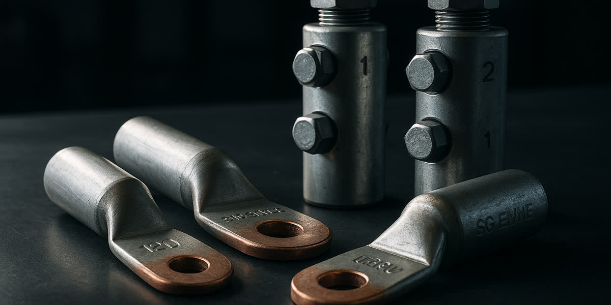
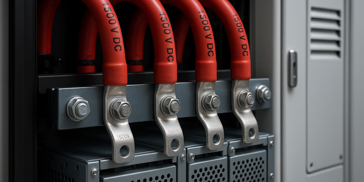
- Galvanic Compatibility: Aluminum conductors must never come into direct, un-greased contact with galvanized steel or copper. Direct copper-to-aluminum contact produces severe bimetallic electrolytic cell corrosion (potential difference $\approx 2.0\text{ V}$). Where overhead conductors transition to substation equipment or switchgear, utilities must install certified friction-welded cable lugs & bimetallic terminals pre-coated with conductive antioxidant paste.
- Hot-Dip Galvanization: All ferrous forged links, U-bolts, and shackles must undergo hot-dip galvanizing in accordance with ASTM A153 or ISO 1461, providing a minimum zinc coating thickness of 85 $\mu$m ($610\text{ g/m}^2$) to withstand 30+ years in industrial (C3/C4) and coastal marine (C5) environments.
- Aluminum Metallurgy: Suspension bodies and compression sleeves utilize structural aluminum alloy (Al-Mg-Si or Al-Si alloy) aged to T6 temper, delivering tensile yield strength $>240\text{ MPa}$ combined with exceptional elongation ($\ge 12\%$) to absorb dynamic impulse shocks without brittle fracture.
5. Engineering Selection Matrix: Hardware by Conductor & System Voltage
To streamline procurement and engineering design, the following matrix pairs typical utility conductor configurations with verified hardware specifications:
| Grid Voltage & Conductor Type | Typical Conductor Spec | Dead-End Clamp Assembly | Suspension Clamp Assembly | Protective / Vibration Hardware |
|---|---|---|---|---|
| 0.4 kV – 1 kV LV Distribution | 3×70+54.6 mm² ABC Cable (aerial bundled cable) | Wedge-type dead-end anchoring clamp (thermoplastic/aluminum alloy body) | Pulley-assisted envelope suspension clamp with UV-resistant plastic insert | Insulation Piercing Connectors (IPC), stainless steel banding straps |
| 11 kV – 33 kV MV Distribution | 100 mm² – 150 mm² AAAC / Tree Wire (tree wire range) | High-strength Bolted Strain Clamp (NLD-3/4) or Helical Dead-End Grip | Cast Aluminum Trunnion Clamp + preformed line guards | Helical Armour Rods, spiral vibration dampers, arc protection horns |
| 66 kV – 132 kV Sub-Transmission | 240/40 mm² ACSR Hawk / Wolf Conductor | Hexagonal Hydraulic Compression Dead-End (Two-Sleeve, 95% RTS) | Armour Grip Suspension (AGS) with neoprene elastomer insert | Stockbridge 4-resonance dampers, bimetallic terminal jumper lugs |
| 220 kV – 500 kV EHV Transmission | 4×400 mm² ACSR Curlew (Bundled) + OPGW | Heavy-duty compression dead-end + multi-bundle yoke plates (160–300 kN MFL) | Tandem AGS double suspension string + ball-socket links | Corona grading rings, spacer dampers (rigid/damping type), Stockbridge dampers |
| Substation & Underground Interface | MV/HV XLPE Underground Cable (power cable line) | Compression termination palm or shear-bolt connector | Wall/structure supporting cleats (IEC 61914 certified) | Heat-shrink / cold-shrink terminations, surge arresters, grounding bus links |
6. Manufacturing Quality Assurance & SiTong Testing Protocols
Hardware failures on energized transmission lines carry catastrophic consequences: unpredicted grid blackouts, structural tower damage, and severe safety hazards. At Zhengzhou Sitong Cable Co., Ltd. (SiTong Cable), our hardware manufacturing and supply chain comply with strict ISO 9001 quality management protocols. Every production batch undergoes rigorous laboratory type testing and routine inspection:
- Tensile & Holding Strength Proof Test (IEC 61284 Clause 11): Hardware samples are subjected to 100% of proof load for 60 seconds without slip or yield, followed by destructive tensile testing to confirm MFL exceeds guaranteed ratings.
- Electrical Temperature Rise & Cycle Test (IEC 61284 Clause 13 / ANSI C119.4): 500 thermal load cycles from ambient to 120°C. Contact resistance across jumper and connector interfaces must remain stable ($\le 1.0 \times$ reference conductor resistance) without thermal runaway.
- Magnetic Power Loss Test for Ferrous Hardware: Measures eddy current and hysteresis heating losses in strain and suspension clamps under heavy operating currents (up to 1200 A), ensuring clamp temperature remains below $75^\circ\text{C}$.
- Zinc Coating Adhesion & Purity Test: Preece copper sulfate dipping tests and magnetic thickness measurements verify uniform, pore-free hot-dip zinc coverage across all forged steel shackles, ball eyes, and clevis links.
Frequently Asked Questions (FAQ)
Q1: What is the primary difference between a bolted strain clamp and a compression dead-end clamp?
A bolted strain clamp (such as the NLD series) utilizes mechanical friction generated by tightening U-bolts over curved conductor clamping channels. It provides an average holding strength of 65%–85% of conductor RTS and allows non-destructive disassembly and tension adjustments, making it well-suited for medium-voltage distribution lines (≤35 kV). In contrast, a compression dead-end clamp uses hydraulic dies to permanently deform separate structural steel and aluminum sleeves onto the core and outer strands, developing ≥95% to 100% of conductor RTS. Compression dead-ends are mandatory for high-voltage and extra-high-voltage transmission lines (66 kV to 500 kV) due to their superior mechanical strength, permanent low contact resistance, and smooth corona-free exterior contours.
Q2: Why are Armour Grip Suspension (AGS) clamps preferred over standard trunnion clamps on EHV transmission spans?
Standard cast aluminum trunnion clamps create a rigid, sharp pivot edge where the conductor enters and exits the clamp body. Under wind-induced aeolian vibration and dynamic galloping, this rigid interface induces extreme alternating bending stresses and fretting wear on the outer aluminum strands, leading to premature fatigue cracking. An Armour Grip Suspension (AGS) assembly replaces the rigid seat with a resilient neoprene elastomer cushion encased in preformed helical armour rods. This composite assembly dampens dynamic flexural stresses by up to 60%, eliminates metal-to-metal fretting, and spreads mechanical clamping pressure over a length of 1 to 2 meters, dramatically extending conductor operational lifespan on long spans and river crossings.
Q3: How do preformed helical dead-ends prevent damage to OPGW fiber optic cores?
Optical Ground Wire (OPGW) contains delicate optical fiber units inside stainless steel or aluminum buffer tubes situated beneath protective outer wire layers. Applying standard bolted or hydraulic compression clamps to an OPGW cable creates severe localized radial pinch forces that crush the buffer tubes, causing micro-bending light loss or permanent fiber breakage. Helical preformed dead-ends are fabricated from high-strength aluminum-clad steel (ACS) wires pre-twisted into an interlocking spiral geometry. When wrapped around the cable, the helical grip distributes radial gripping force evenly across an extended contact length (often exceeding 1.5 meters). This allows the fitting to achieve 100% of the cable's mechanical tensile rating without transmitting damaging radial compression to the internal optical fibers.
Q4: What causes galvanic corrosion between conductors and pole line hardware, and how is it prevented?
Galvanic corrosion occurs when two electrochemically dissimilar metals—such as an aluminum conductor and a copper terminal stud or ungalvanized steel bolt—come into contact in the presence of an electrolyte (atmospheric moisture, rain, or salt-laden coastal humidity). Because aluminum is significantly more anodic (-1.66 V standard reduction potential) than copper (+0.34 V) or iron (-0.44 V), the aluminum sacrificial anode rapidly corrodes, resulting in pitting, high joint resistance, localized overheating, and eventual structural severance. Prevention methods include using compatible high-grade aluminum alloy hardware bodies for aluminum conductors, applying heavy hot-dip zinc coatings (≥85 µm) to steel components to serve as a sacrificial barrier, employing friction-welded bimetallic transition lugs (Cu-Al), and injecting non-drying silicone-based antioxidant contact grease to hermetically seal joint interfaces against moisture penetration.
Engineered Transmission Lines & Hardware Solutions by SiTong Cable
Building a reliable, future-proof overhead electrical network requires precision coordination between conductors and their supporting hardware infrastructure. Zhengzhou Sitong Cable Co., Ltd. (SiTong Cable) delivers integrated, end-to-end transmission solutions tailored to your utility or EPC project requirements:
👉 Explore our comprehensive Pole Line Fittings & Hardware Catalog
👉 Browse our Heavy-Duty Cable Lugs & Bimetallic Terminals
👉 Discover our High-Capacity ACSR Conductor Line
👉 Consult our Senior Engineering Team for Custom Overhead Line Hardware & Conductor Sizing
📬 Engineering & Export Inquiries: sales@sitongcable.com | 📞 Technical Hotline: +86-371-69176007