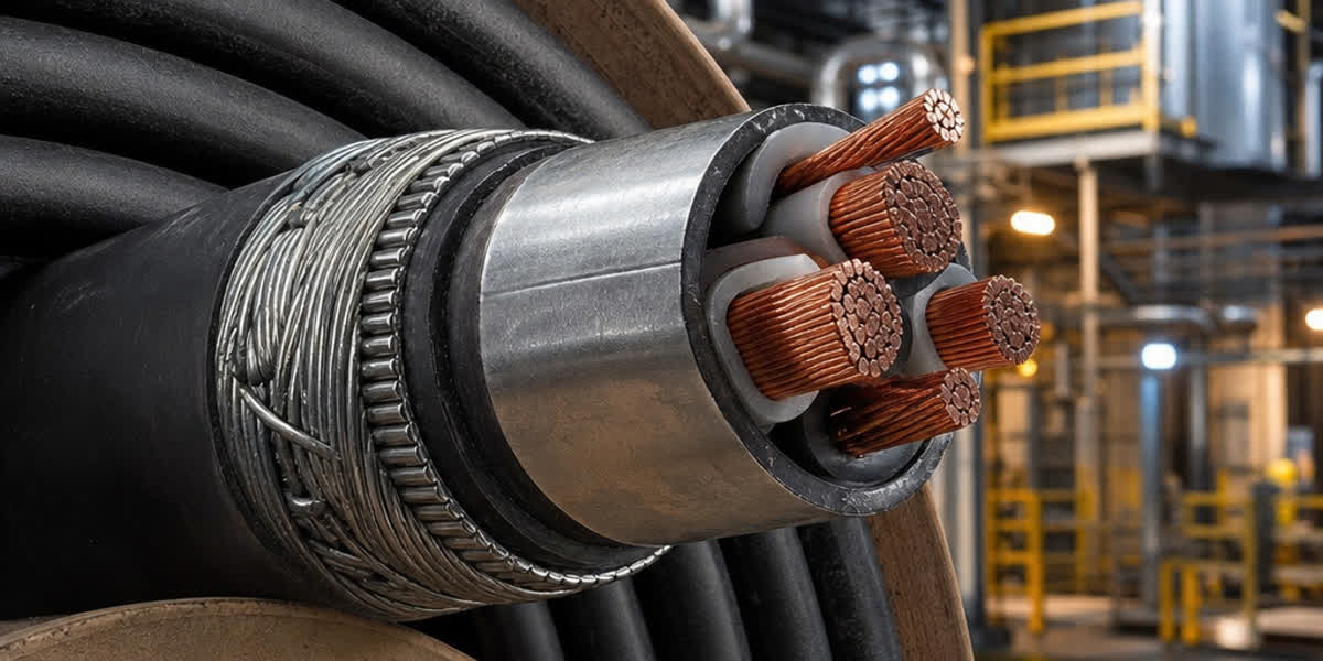
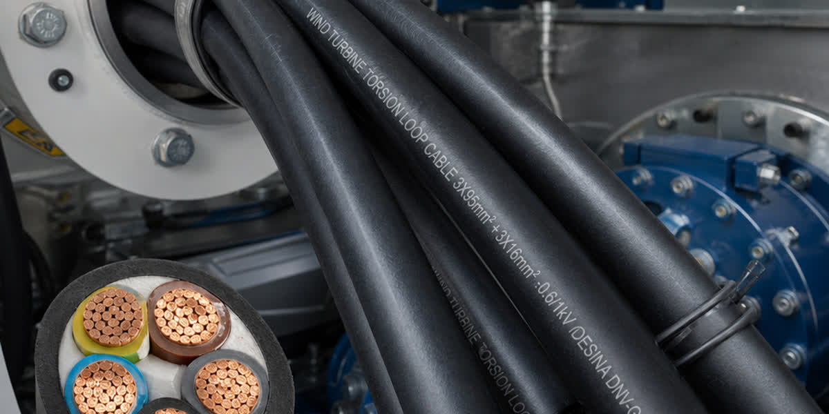
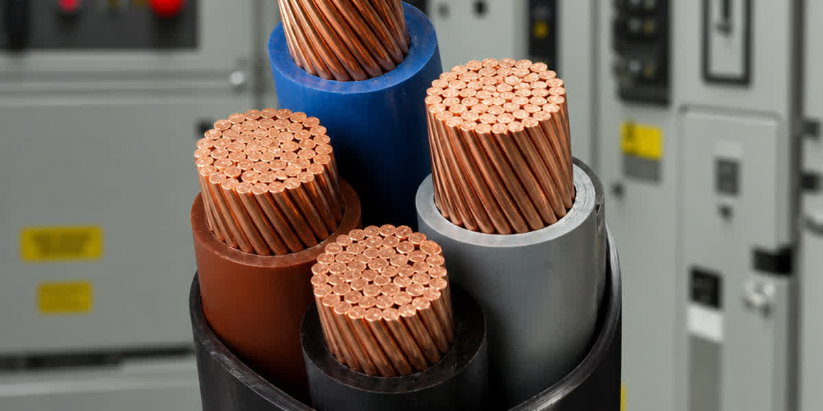
Data Center Power Cabling Engineering Guide: MV Feeders, LSZH Fire Safety, Harmonics & Sizing (TIA-942, IEC 60332)
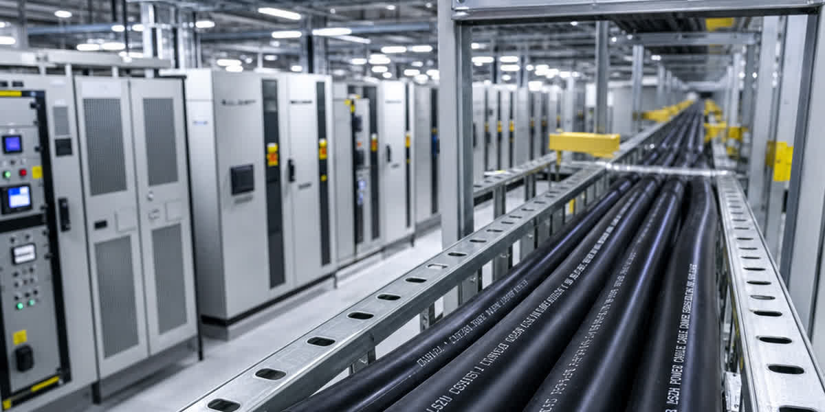
Data Center Power Cabling Engineering Guide: MV Feeders, LSZH Fire Safety, Harmonics & Sizing (TIA-942, IEC 60332)
Master data center power cabling: MV feeders, LSZH fire safety, triplen harmonics, neutral sizing, and busway vs cable selection per IEC standards.
Modern hyperscale, enterprise, and colocation data centers operate under unprecedented electrical power densities. Driven by high-density artificial intelligence (AI) compute clusters, graphics processing units (GPUs), and cloud infrastructure, modern facilities routinely design for power densities exceeding 30 kW to 100 kW per rack. In this mission-critical environment, where downtime costs can exceed tens of thousands of dollars per second, the electrical distribution network is the lifeblood of operations.
Engineering the power delivery infrastructure for an ANSI/TIA-942 Rated 3 (Tier III) or Rated 4 (Tier IV) data center requires an uncompromising approach to power cable selection, ampacity derating, harmonic current handling, and fire safety. Unlike conventional commercial buildings, data centers combine 100% continuous operational duty cycles, massive non-linear electronic switched-mode power supply (SMPS) loads, stringent space constraints, and sensitive electronic hardware vulnerable to microscopic airborne contaminants.
This comprehensive technical guide examines the end-to-end engineering principles governing data center power cabling—from utility substation medium-voltage (MV) incoming feeders down to computer room power distribution units (PDUs). We detail the physical phenomena behind triplen harmonic neutral heating, evaluate Low Smoke Zero Halogen (LSZH) chemical safety standards, analyze short-circuit dynamic stresses, compare busway systems versus multi-conductor cable topologies, and provide actionable sizing calculations aligned with IEC, NEC, and TIA standards.
1. Data Center Power Distribution Architecture: From Grid to Server
A resilient data center electrical architecture is divided into distinct operational zones, each presenting unique electrical, thermal, and mechanical stresses on power conductors. To maintain concurrently maintainable or fault-tolerant operation (2N or distributed redundant topologies), dual independent distribution paths (Path A and Path B) must be maintained from independent utility substations through to the server power supply units (PSUs).
Utility Substation (11kV / 22kV / 33kV)
                │
                ▼
Medium-Voltage (MV) Intake Switchgear ─── Standby Diesel Generators / Gas Turbines
                │
                ▼
Step-Down Transformers (MV to 400V / 480V LV)
                │
                ▼
Main Low-Voltage Switchboard (Main LV Switchgear)
                │
                ▼
Uninterruptible Power Supply (UPS) Systems & Battery Energy Storage
                │
                ▼
Power Distribution Units (PDUs) / Remote Power Panels (RPPs)
                │
                ▼
Busway Tap-Off Boxes / Rack Power Distribution Units (rPDUs)
                │
                ▼
Dual-Corded Server Power Supplies (A/B Feeds)
Cable Functional Classification Across Facility Zones
The following matrix summarizes the primary power cabling technologies utilized across modern data center facilities:
| Facility Zone | Nominal Voltage | Conductor & Insulation System | Mechanical Protection | Relevant Standards |
|---|---|---|---|---|
| Grid Substation to Intake | 11 kV to 33 kV (MV) | Stranded Compact Copper or Aluminium, Tree-Retardant XLPE (TR-XLPE), Semi-conductive screens | Aluminium Wire Armoured (AWA) for single-core; Steel Wire Armoured (SWA) for three-core | IEC 60502-2, BS 6622, ICEA S-94-649 |
| Generator to Main Switchboard | 400 V / 480 V (LV) | Class 2 Stranded or Class 5 Flexible Copper, 90°C XLPE or EPR insulation | Flame-Retardant LSZH outer sheath, optional SWA or heavy braiding | IEC 60502-1, BS 6724, UL 1277 |
| UPS to Battery Storage | Up to 1000 V DC | Flexible Tinned Copper, Heavy-Duty EPDM / EPR / XLPO compound | Chemical, acid, and fire-retardant LSZH sheath | UL 44, EN 50618, IEC 60245 |
| Main LV to PDUs / RPPs | 400 V / 480 V (3P+N+PE) | High-Conductivity Electrolytic Copper, 90°C XLPE insulation | Multi-core SWA LSZH or Metal-Clad (MC) continuous corrugated aluminium armour | IEC 60364-5-52, BS 6724, NEC Article 330 |
| PDU to Server Rack | 208 V / 230 V / 400 V | Single or Multi-core Copper, High-temperature LSZH or THHN/XHHW-2 | Overhead cable trays or overhead modular busway tap-off whips | IEC 60332-3, UL 83, UL 44, TIA-942 |
When engineers design long-run external feeds from utility substations through underground duct banks or concrete trenches, specifying robust direct burial underground cables with longitudinal water-blocking tapes and radial moisture barriers is essential to eliminate water-tree degradation over the facility's 30-year lifecycle.
2. Low Smoke Zero Halogen (LSZH) vs. Standard PVC: The Physics of Corrosive Gas Damage
In commercial and industrial building services, standard Polyvinyl Chloride (PVC) insulated and sheathed cables remain prevalent due to low cost and mechanical flexibility. However, within data center white space (server rooms) and grey space (electrical rooms), the use of halogenated compounds represents an existential operational risk.
The Chemical Mechanism of Halogen Gas Degradation
PVC contains approximately 56% chlorine by molecular weight. When subjected to localized electrical faults, arcing, or external fire temperatures exceeding 250°C, the polymer undergoes rapid thermal dehydrochlorination, releasing massive quantities of gaseous hydrogen chloride ($HCl$):
$$\text{--}[CH_2\text{--}CHCl]_n\text{--} \xrightarrow{\Delta} n\,HCl\uparrow + \text{carbonaceous char / smoke}$$
When released into a data center environment, anhydrous $HCl$ gas combines instantaneously with ambient atmospheric moisture (or vaporized water from fire suppression systems) to form concentrated hydrochloric acid mist:
$$HCl_{(g)} + H_2O \rightarrow H_3O^+ + Cl^-_{(aq)}$$
This acidic vapor is circulated instantly throughout the white space via high-velocity Computer Room Air Handling (CRAH) and fan-wall units. The airborne chloride ions deposit onto server motherboards, microchip lead frames, memory sockets, and optical transceivers. Hydrochloric acid aggressively corrodes microscopic copper traces and silver-plated contact surfaces, causing bridging short-circuits and permanent latent component failure across thousands of servers—even if the physical fire was confined to a single breaker cubicle.
Furthermore, burning PVC produces dense, opaque smoke rich in toxic carbon monoxide and dioxins, dropping optical transmittance to near zero within seconds, obscuring egress pathways and obstructing technician intervention.
International LSZH Testing Standards & Compliance Thresholds
To safeguard both mission-critical IT silicon and human personnel, modern data centers mandate flame-retardant medium-voltage and low-voltage power cables manufactured with advanced Low Smoke Zero Halogen (LSZH / LSOH / OHLS) thermoplastic or thermoset polyolefin materials. Strict compliance requires verification across three independent international testing dimensions:
┌────────────────────────────────────────────────────────────────────────┐
│               LSZH TRI-STANDARD VERIFICATION FRAMEWORK                  │
├────────────────────────┬───────────────────────┬───────────────────────┤
│ 1. Flammability        │ 2. Halogen Content    │ 3. Smoke Density      │
│    IEC 60332-3-24      │    IEC 60754-1 & -2   │    IEC 61034-2        │
│    (Category C Bunch)  │    (Acid Gas Release) │    (Light Transmittance)│
│                        │                       │                       │
│ • Vertical flame spread│ • Halogen acid < 0.5% │ • 3-meter cube test   │
│   <= 2.5 meters        │ • pH >= 4.3           │ • Min transmittance   │
│ • Self-extinguishing   │ • Conductivity        │   >= 60% (typically   │
│   after burn duration  │   <= 10 uS/mm         │   > 80% for SiTong)   │
└────────────────────────┴───────────────────────┴───────────────────────┘
               [Standard Comparison: PVC vs. High-Performance LSZH]

  Test Parameter           Standard Test Ref.     Standard PVC Cable     High-Grade LSZH Cable
  ─────────────────────────────────────────────────────────────────────────────────────────────
  Halogen Acid Gas ($HCl$) IEC 60754-1            200 to 350 mg/g        < 5 mg/g (Zero Halogen)
  Combustion Solution pH   IEC 60754-2            < 2.5 (Highly Acidic)  >= 4.3 (Non-Corrosive)
  Conductivity             IEC 60754-2            > 150 uS/mm            <= 10 uS/mm
  Smoke Transmittance      IEC 61034-2            15% to 35% (Opaque)    >= 60% to 85% (Clear)
  Flame Propagation        IEC 60332-3-24 (Cat C) Continuous Burn        Self-Extinguishing <=2.5m
  Electronic Toxicity      Corrosivity Test       Severe PCB Etching     Zero Metallic Etching
All specialized data center power lines engineered by Zhengzhou Sitong Cable Co., Ltd. (SiTong Cable) utilize high-purity irradiated cross-linked polyolefin (XLPO) or zero-halogen flame-retardant compounds meeting or exceeding IEC 60754, IEC 61034, and UL 1685 vertical tray flame requirements.
3. Harmonic Distortion and Neutral Conductor Sizing in High-Density Facilities
In legacy electrical systems, 3-phase 4-wire distribution assumes balanced linear loads, where neutral current is approximately zero:
$$\vec{I}_N = \vec{I}_A + \vec{I}_B + \vec{I}_C \approx 0$$
Under this assumption, designers frequently specified reduced-neutral cables (e.g., $3 \times 185 + 1 \times 95 \text{ mm}^2$). In modern hyperscale data centers, this assumption is catastrophic.
The Physics of Triplen Harmonics
Servers, storage arrays, core network switches, and uninterruptible power supply (UPS) rectifiers utilize switched-mode power supplies (SMPS) to convert AC mains to DC bus voltages. Even with modern Power Factor Correction (PFC) stages operating at full load, servers draw non-linear pulsed currents.
Fourier decomposition of non-linear current waveforms reveals significant odd harmonic components:
$$i(t) = I_1 \sin(\omega t) + I_3 \sin(3\omega t) + I_5 \sin(5\omega t) + I_7 \sin(7\omega t) + \dots + I_n \sin(n\omega t)$$
The third harmonic ($150 \text{ Hz}$ in $50 \text{ Hz}$ grids, $180 \text{ Hz}$ in $60 \text{ Hz}$ grids) and its odd multiples (9th, 15th, 21st)—collectively termed triplen harmonics—exhibit a zero-sequence phase displacement:
$$\theta_3 = 3 \times 0^\circ = 0^\circ, \quad 3 \times 120^\circ = 360^\circ \equiv 0^\circ, \quad 3 \times 240^\circ = 720^\circ \equiv 0^\circ$$
Because triplen harmonics in all three phases are entirely in phase with each other, they do not cancel at the neutral star point. Instead, they add arithmetically in the neutral conductor:
$$I_{N(3rd)} = I_{A(3rd)} + I_{B(3rd)} + I_{C(3rd)} = 3 \times I_{phase(3rd)}$$
Total root-mean-square (RMS) neutral current, taking into account fundamental imbalance and harmonic summation across all orders, is calculated as:
$$I_N = \sqrt{I_{N(1)}^2 + \sum_{h=3,6,9\dots} (3 \cdot I_{phase(h)})^2}$$
In server rooms operating with Total Harmonic Current Distortion ($THD_i$) between 30% and 45%, the neutral conductor routinely carries continuous currents ranging from 120% to 175% of the nominal phase current.
Skin Effect and Proximity Losses at Harmonic Frequencies
Compounding the problem of increased RMS current is the skin effect. The alternating magnetic field inside the conductor forces current toward the outer circumference. The effective skin depth ($\delta$) decreases inversely with the square root of frequency:
$$\delta = \sqrt{\frac{\rho}{\pi f \mu_0 \mu_r}}$$
| Harmonic Order | Frequency ($50 \text{ Hz}$ Base) | Frequency ($60 \text{ Hz}$ Base) | Copper Skin Depth $\delta$ (mm) | $R_{AC} / R_{DC}$ ($240 \text{ mm}^2$ Cu) |
|---|---|---|---|---|
| Fundamental (1st) | 50 Hz | 60 Hz | 9.38 mm | 1.02 |
| 3rd Harmonic | 150 Hz | 180 Hz | 5.41 mm | 1.15 |
| 5th Harmonic | 250 Hz | 300 Hz | 4.19 mm | 1.28 |
| 9th Harmonic | 450 Hz | 540 Hz | 3.12 mm | 1.54 |
| 15th Harmonic | 750 Hz | 900 Hz | 2.42 mm | 1.88 |
Because AC resistance increases significantly at harmonic frequencies, high harmonic neutral currents generate intense localized Joule heating ($I_N^2 R_{AC}$).
Engineering Mitigation: The 200% Oversized Neutral Rule
To prevent catastrophic insulation degradation, fire hazard, and neutral burn-out, electrical engineers must enforce the following design rules in data center distribution:
- Mandatory 200% Neutral Sizing: For all low-voltage distribution between UPS output, PDUs, and RPPs, specify double-capacity neutral conductors ($2 \times$ Phase Cross-Section). Multi-conductor configurations must utilize $4 \times \text{Phase} + 2 \times \text{Neutral}$ or parallel matching neutral runs.
- Derating Factor Application (IEC 60364-5-52 Annex E):
- If third harmonic content is $15\% < THD_3 \le 33\%$, the phase conductors must be derated by a factor of 0.86.
- If third harmonic content is $> 33\%$, cable sizing must be calculated based directly on the neutral current, applying a derating factor of 0.86 to the neutral capacity.
- Dedicated Phase/Neutral Parity: Never share neutral conductors across single-phase branch circuits. Every branch circuit supplying rack PDUs must feature a dedicated neutral conductor matching or exceeding the phase conductor rating.
4. Busway vs. Armoured Cable: Technical-Economic Matrix for Data Center White and Grey Space
A central debate in data center facility design centers on whether to deploy overhead modular busway (busduct) systems or multi-conductor armoured cable runs for power delivery from PDUs to server racks.
                  ┌──────────────────────────────────────────────────┐
                  │ BUSWAY VS. ARMOURED CABLE EVALUATION FRAMEWORK   │
                  └────────────────────────┬─────────────────────────┘
                                           │
         ┌─────────────────────────────────┴─────────────────────────────────┐
         ▼                                                                   ▼
┌─────────────────────────────────┐                 ┌─────────────────────────────────┐
│     Overhead Modular Busway     │                 │   Armoured LSZH Cable Trays     │
├─────────────────────────────────┤                 ├─────────────────────────────────┤
│ • Pre-engineered track system   │                 │ • SWA / AWA / MC armoured runs  │
│ • Plug-and-play tap-off boxes   │                 │ • Fixed point-to-point routes   │
│ • High initial material CAPEX   │                 │ • Low initial material CAPEX    │
│ • Rapid rack reconfiguration    │                 │ • High structural weight load   │
│ • Strict joint torque checks    │                 │ • High installation labor hours │
│ • Lower continuous copper mass  │                 │ • Superior continuous screening │
└─────────────────────────────────┘                 └─────────────────────────────────┘
Detailed Engineering Trade-Off Matrix
The choice between modular overhead busway and armoured cable depends on facility tier rating, white-space tenant churn rate, floor ceiling heights, and capital expenditure targets:
| Technical Parameter | Overhead Modular Busway (Track Busway) | Armoured LSZH Multi-Core Cable (SWA / MC) | Engineering Assessment & Optimal Application |
|---|---|---|---|
| Initial Capital Cost (CAPEX) | High (35% to 60% premium over cable) | Low to Moderate (standardized bulk commodity) | Cable offers substantial initial savings for dedicated single-tenant enterprise builds with fixed 5-year floor plans. |
| Deployment Flexibility | Ultra-high: Tap-off units plug in live within 15 minutes | Low: Modifying circuits requires pulling new cables | Busway is ideal for colocation data centers with unpredictable rack densities and tenant moves. |
| Physical Space & Airflow | Compact rectangular profile (100–150 mm depth) | Bulky bundled cable trays obstruct under-floor or overhead hot-air return paths | Busway preserves overhead ceiling plenum aerodynamics, lowering cooling fan energy consumption. |
| Floor Loading & Ceiling Weight | Lightweight aluminium housing (12–25 kg/m) | Heavy cable bundles in ladder racks (40–90 kg/m) | In multi-story data centers or seismic zones, cable bundle weights can exceed structural ceiling hanger limits. |
| Thermal Dissipation | Direct radiation from extruded aluminum casing | Bundle derating applies ($k_{group} \approx 0.65 - 0.70$ in multi-tier trays) | Cables in congested trays require significant cross-sectional oversizing to compensate for thermal grouping. |
| Electromagnetic Shielding | Aluminium housing provides moderate EMI shield | Continuous steel/aluminium wire armour provides superior magnetic field attenuation | Armoured cable is superior when routing adjacent to sensitive instrumentation and control cables. |
| Reliability & Failure Points | Joint bolt connections every 3 meters require periodic infrared thermography | Continuous uninterrupted copper conductor from breaker to rack PDU | Cable eliminates intermediate mechanical connection joints, reducing latent thermal connection failures. |
The Hybrid Engineering Consensus: Tier III/IV facility designers increasingly adopt a hybrid topology: - Grey Space (Electrical Rooms): High-ampacity armoured low-smoke zero-halogen power cables or high-flexibility feeder cables are used from generators to main switchboards and transformers to UPS rooms. Cable routes accommodate complex elevations, structural offsets, and wall penetrations. - White Space (Server Compute Halls): Modular overhead track busway is deployed directly above server rack aisles to allow rapid deployment of tap-off units as IT power densities evolve.
5. Short-Circuit Thermal Sizing and Dynamic Magnetic Forces
Data center main low-voltage switchboards are connected to multi-megavolt-ampere (MVA) utility transformers operating in parallel with on-site standby generation. Prospective short-circuit fault currents frequently reach 50 kA, 65 kA, or even 100 kA RMS with fault durations up to 100 to 200 milliseconds before downstream breaker clearance.
Cables subjected to these extreme electrical faults must satisfy two distinct failure criteria: adiabatic thermal limits and dynamic electromagnetic deflection forces.
1. Conductor Thermal Sizing (Adiabatic Limit)
Under short-circuit conditions ($t \le 5 \text{ seconds}$), heat transfer from the conductor through the insulation is negligible. The minimum required conductor cross-sectional area ($S$) is calculated using the adiabatic formula specified in IEC 60364-5-54 and BS 7671:
$$S = \frac{\sqrt{I_{sc}^2 \cdot t}}{k} = \frac{I_{sc} \cdot \sqrt{t}}{k}$$
Where: - $S$ = Minimum conductor cross-sectional area ($\text{mm}^2$) - $I_{sc}$ = Prospective symmetrical short-circuit current RMS ($\text{A}$) - $t$ = Total clearing time of the protective device ($\text{seconds}$) - $k$ = Thermal material factor ($\text{A}\cdot\text{s}^{1/2}/\text{mm}^2$), determined by initial operating temperature and maximum permissible short-circuit temperature:
$$k = \sqrt{\frac{Q_c \cdot (\beta + 20)}{\rho_{20}} \cdot \ln\left(\frac{\beta + \theta_f}{\beta + \theta_i}\right)}$$
For standard high-grade cable insulation systems: - Copper Conductor with 90°C XLPE / LSZH Insulation ($\theta_i = 90^\circ\text{C}, \theta_f = 250^\circ\text{C}$): $k = 143$ - Aluminium Conductor with 90°C XLPE / LSZH Insulation ($\theta_i = 90^\circ\text{C}, \theta_f = 250^\circ\text{C}$): $k = 94$ - Copper Conductor with 70°C Thermoplastic PVC Insulation ($\theta_i = 70^\circ\text{C}, \theta_f = 160^\circ\text{C}$): $k = 115$
Engineering Worked Example:
Consider a data center main distribution feeder exposed to a prospective symmetrical fault current of $I_{sc} = 65,000 \text{ A}$ ($65 \text{ kA}$) with a backup breaker clearance time of $t = 0.12 \text{ seconds}$ ($120 \text{ ms}$). The minimum copper conductor size using XLPE/LSZH insulation is:
$$S_{min} = \frac{65,000 \times \sqrt{0.12}}{143} = \frac{65,000 \times 0.3464}{143} = 157.45 \text{ mm}^2$$
The nearest standard commercial cross-section is $185 \text{ mm}^2$. If aluminium were specified:
$$S_{min(Al)} = \frac{65,000 \times 0.3464}{94} = 239.53 \text{ mm}^2 \implies \mathbf{240 \text{ mm}^2}$$
2. Electromechanical Short-Circuit Forces and Cable Cleating
During a short-circuit event, parallel single-core conductors carry peak asymmetric fault currents ($I_p = 2.55 \times I_{sc}$), generating massive electromagnetic repulsion forces ($F_s$) described by Ampère's Force Law:
$$F_s = 0.2 \times \frac{I_p^2}{S_{spacing}} \quad (\text{N/m})$$
Where: - $F_s$ = Peak dynamic force per unit length ($\text{N/m}$) - $I_p$ = Peak short-circuit current ($\text{kA}$) - $S_{spacing}$ = Center-to-center spacing between adjacent conductors ($\text{m}$)
For a 65 kA RMS fault with peak current $I_p = 165.75 \text{ kA}$ routed in trefoil formation with cable center-to-center diameter $d = 0.05 \text{ m}$ ($50 \text{ mm}$):
$$F_s = 0.2 \times \frac{165.75^2}{0.05} = 0.2 \times \frac{27,473}{0.05} = \mathbf{109,892 \text{ N/m}} \quad (\approx 11.2 \text{ tons force per meter!})$$
Without rigid, engineered mechanical restraint, the conductors will violently deflect, rupturing cable trays, crushing adjacent control wires, and causing phase-to-phase catastrophic arc flash.
Engineers must specify calibrated, non-magnetic trefoil cable cleats compliant with IEC 61914. Cleat spacing ($L_c$) along cable ladders must be calculated based on the maximum rated cleat holding capacity ($F_{cleat}$):
$$L_c \le \frac{F_{cleat}}{F_s}$$
For all heavy single-core feeders, installing certified cable cleat restraints and support hardware at intervals no greater than 300 mm to 600 mm is an absolute safety mandate in mission-critical data center substations.
6. End-to-End Cable Sizing & Ampacity Derating Calculation
In a mission-critical data center, cables cannot be sized based solely on nominal equipment nameplates. System designers must account for continuous ambient room temperatures, dense grouping in multi-tier cable ladders, non-linear harmonic heating, and terminal temperature limits.
                  ┌─────────────────────────────────────────────────────────┐
                  │ CABLE AMPACITY DERATING MULTIPLIER CHAIN (IEC 60364)    │
                  └────────────────────────────┬────────────────────────────┘
                                               │
             ┌─────────────────────────────────┴─────────────────────────────────┐
             ▼                                 ▼                                 ▼
┌─────────────────────────┐       ┌─────────────────────────┐       ┌─────────────────────────┐
│ Ambient Temp ($k_{temp}$)│   ×   │ Cable Grouping ($k_{grp}$)│   ×   │ Harmonics ($k_{harm}$)  │
├─────────────────────────┤       ├─────────────────────────┤       ├─────────────────────────┤
│ Baseline: 30°C in air   │       │ Tray filling & bundling │       │ Triplen neutral content │
│ E.g., 40°C air in tray  │       │ E.g., 6 circuits in     │       │ E.g., 20% THD3 content  │
│ factor = 0.91 (XLPE)    │       │ touching tray = 0.73    │       │ factor = 0.86           │
└─────────────────────────┘       └─────────────────────────┘       └─────────────────────────┘
                                               │
                                               ▼
                             Total Derating: $k_{total} = 0.91 \times 0.73 \times 0.86 = 0.571$
                             Effective Ampacity: $I_z = I_{tabulated} \times k_{total}$
Derating Formula
The permissible continuous current-carrying capacity ($I_z$) under actual operating conditions is given by:
$$I_z = I_0 \times k_{temp} \times k_{group} \times k_{harm} \times k_{soil}$$
Where: - $I_0$ = Tabulated nominal ampacity under reference conditions (IEC 60364-5-52 or NEC Table 310.16) - $k_{temp}$ = Correction factor for ambient temperature (often 35°C to 45°C in overhead hot-aisle containment return plenums) - $k_{group}$ = Grouping derating factor for adjacent touching cables in ladder racks - $k_{harm}$ = Non-linear harmonic distortion derating factor (IEC 60364-5-52 Annex E) - $k_{soil}$ = Thermal resistivity correction for underground intake feeders
Comprehensive Step-by-Step Design Calculation
Design Scenario: Size a low-voltage feeder connecting a 400 V, 1000 kVA UPS output switchboard to a main computer room PDU.
Step 1: Continuous Full-Load Current Calculation
$$\text{Full-Load Current } I_L = \frac{S_{kVA} \times 1000}{\sqrt{3} \times V_{LL}} = \frac{1000 \times 1000}{\sqrt{3} \times 400} = \frac{1,000,000}{692.82} = \mathbf{1443.4 \text{ A}}$$
Applying the continuous load safety factor of 125% per NEC Article 215 / TIA-942: $$I_{design} = 1443.4 \times 1.25 = \mathbf{1804.2 \text{ A}}$$
Step 2: Parallel Cable Selection
Due to physical cable bending radius and termination constraints, carrying 1804 A requires parallel single-core conductors per phase. We select 4 parallel circuits of single-core $300 \text{ mm}^2$ Class 2 copper XLPE/LSZH conductors in trefoil formation.
Target design current per conductor: $$I_{target / cond} = \frac{1804.2 \text{ A}}{4} = \mathbf{451.05 \text{ A}}$$
Step 3: Application of Environmental and Installation Derating Factors
- Ambient Temperature: Overhead cable tray in electrical room operating at 40°C. For 90°C XLPE insulation: $$k_{temp} = 0.91$$
- Grouping Factor: 4 parallel trefoil groups arranged on an open perforated cable ladder with 50 mm clearance: $$k_{group} = 0.88$$
- Harmonic Factor: Measured downstream IT load exhibiting $THD_3 = 22\%$: $$k_{harm} = 0.86$$
Combined overall derating multiplier: $$k_{total} = k_{temp} \times k_{group} \times k_{harm} = 0.91 \times 0.88 \times 0.86 = \mathbf{0.6887}$$
Step 4: Verification of Effective Ampacity
From IEC 60364-5-52 Table B.52.12 (Method F, single-core cables touching in trefoil in free air, copper conductor, 90°C insulation): - Tabulated base ampacity for $300 \text{ mm}^2$ Cu: $I_0 = 741 \text{ A}$
Effective derated ampacity ($I_z$): $$I_z = I_0 \times k_{total} = 741 \text{ A} \times 0.6887 = \mathbf{510.3 \text{ A}}$$
Comparison: $$I_z (510.3 \text{ A}) > I_{target / cond} (451.05 \text{ A}) \quad \checkmark \text{ PASSED with 13.1% thermal margin}$$
Step 5: High-Current Termination Engineering
To terminate multiple parallel 300 mm² conductors into compact switchgear breaker stabs without thermal hot spots, technicians must install heavy-duty bimetallic cable lugs or certified shear-bolt mechanical connectors. Calibrated torque wrenches must be used to ensure precise contact pressure according to manufacturer specifications (e.g., 45 N·m for M12 grade 8.8 bolts), preventing thermal relaxation under dynamic 24/7 loading cycles.
For sub-distribution circuits inside server containment aisles, engineers deploy fire-rated building wire and branch circuit conductors routed in dedicated steel conduit to isolate sensitive server supplies from mechanical vibration.
7. Frequently Asked Questions (FAQ)
Q1: Why is LSZH cable mandatory in data centers even when clean-agent gaseous fire suppression (FM-200, Novec 1230, Inergen) is installed?
Gaseous fire suppression systems are designed to extinguish active flames by oxygen displacement or chemical thermal absorption. However, localized electrical overheating or slow smoldering electrical arcing can generate corrosive hydrogen chloride ($HCl$) gas at temperatures as low as 180°C to 250°C—before sufficient heat or smoke accumulates to trigger clean-agent discharge.
Once generated, $HCl$ acid gas immediately enters the high-volume air stream of the data center's cooling infrastructure, causing irreversible microscopic acid corrosion on server circuit boards throughout the hall. Specifying cables certified to IEC 60754-1/2 ($HCl < 0.5\%$, $\text{pH} \ge 4.3$) guarantees that even in extreme localized thermal events, zero corrosive acid is formed.
Q2: How does triplen harmonic current affect neutral conductor sizing in a 3-phase PDU feeder?
Triplen harmonics (3rd, 9th, 15th order) are zero-sequence harmonic currents. Unlike fundamental balanced currents ($50/60 \text{ Hz}$) which cancel out at the neutral star point of a three-phase system, triplen harmonic components from all three phases align in phase and add directly together in the neutral conductor ($I_N \approx 3 \times I_3$). In high-density server environments, this causes the neutral current to exceed phase currents, frequently reaching 130% to 170% of phase load.
Consequently, electrical engineers must specify 200% oversized neutral conductors ($2 \times \text{Phase Cross-Section}$) and apply the 0.86 harmonic derating factor per IEC 60364-5-52 Annex E to prevent neutral overheating and insulation breakdown.
Q3: When should a data center choose modular overhead busway over multi-core armoured cables?
Modular overhead track busway is superior in data center white space (server compute rooms) where rack densities evolve dynamically, tenant equipment rotates frequently, or rapid 15-minute live tap-off additions are required. Busway reduces overhead weight, frees up airflow plenums, and provides plug-and-play reconfiguration.
Conversely, armoured LSZH multi-core cables (such as SWA, AWA, or MC cables) are significantly more cost-effective in grey space (electrical utility intake, generator rooms, and static UPS distribution) where high-ampacity runs are permanent, physical routes involve complex elevation changes and sharp building turns, and maximum physical protection against mechanical impacts is required.
Q4: Can aluminium conductors be used in mission-critical data center power distribution?
Yes, but with strict engineering boundaries. Aluminium conductors (particularly modern AA-8000 series electrical alloys) offer significant cost and weight advantages for long-run medium-voltage (11 kV to 33 kV) utility intake feeders and bulk low-voltage feeder backbones where raceway space is abundant.
However, because aluminium has lower volumetric conductivity than copper (requiring approximately 1.6 times the cross-sectional area for equivalent ampacity), copper conductors remain the gold standard inside high-density computer halls, cramped PDU cabinets, and switchgear enclosures. When aluminium is used, technicians must strictly install certified bimetallic friction-welded lugs or shear-bolt connectors with oxide-inhibiting paste to prevent galvanic corrosion and thermal creep.
Q5: How do dynamic short-circuit electromagnetic forces affect cable tray and cleat design in data center switchrooms?
Under a high prospective fault (e.g., 65 kA RMS), the peak asymmetrical current creates massive magnetic repulsion forces between adjacent conductors, exceeding 100,000 N/m (over 10 tonnes of dynamic force per meter of cable run). If single-core cables in trefoil formation are secured only with standard plastic cable ties, the forces will violently shear the ties, allowing conductors to whip outward, destroy cable trays, and cause secondary short-circuits.
Data center engineering specifications must mandate certified, short-circuit tested non-magnetic cable cleats compliant with IEC 61914, spaced at calculated intervals (typically 300 mm to 600 mm near terminations) to absorb these mechanical shockwaves safely.
8. Conclusion and Engineering Recommendations
Designing the electrical infrastructure of a modern hyperscale or enterprise data center requires balancing high power densities, severe harmonic stresses, strict structural weight limits, and zero-tolerance fire safety requirements.
By mandating tri-standard certified LSZH cables (IEC 60332-3, IEC 60754, IEC 61034), engineers protect sensitive IT silicon from catastrophic acid vapor etching. Applying the 200% neutral conductor rule alongside rigorous skin-effect and grouping deratings safeguards systems against non-linear server harmonics. Combining overhead modular busway in whitespace with rugged, heavy-duty armoured cables in grey space achieves optimal capital efficiency, scalability, and long-term operational resilience.
Zhengzhou Sitong Cable Co., Ltd. (SiTong Cable) is a globally recognized manufacturer of mission-critical electrical cabling systems. With state-of-the-art continuous triple-extrusion lines, dedicated zero-halogen polyolefin compounding, and rigorous in-house laboratory testing for flammability, acid emission, and partial discharge, SiTong Cable delivers certified power solutions to data centers, renewable energy projects, and national utilities in more than 80 countries worldwide.
👉 Browse our Power Cable product range 👉 Harmonics and Neutral Conductor Sizing Engineering Guide 👉 Contact our engineering team
📬 Sales inquiries: sales@sitongcable.com | 📞 Phone: +86-371-69176007