High Temperature Wire: Complete Technical Guide, Standards & Selection Best Practices
High Temperature Wire: Complete Technical Guide, Standards & Selection Best Practices
High temperature wire (also referred to as high-temp lead wire, thermocouple wire, or heat-resistant cable) is a class of electrical conductors engineered to operate reliably in ambient and conductor-surface temperatures ranging from 150°C to 450°C and above, where standard PVC, XLPE, or general-purpose rubber insulation would degrade, embrittle, or fail catastrophically. These specialty cables are indispensable across industries that manage extreme thermal environments — aerospace engine nacelles, automotive engine bays and EV battery packs, industrial furnace thermocouple circuits, power generation turbine instrumentation, oil & gas downhole sensor arrays, and steel mill continuous-casting machinery. Selecting the correct high-temperature wire requires navigating a matrix of conductor metallurgy, insulation chemistry, applicable international standards, and installation constraints. This guide provides engineers and procurement professionals with a structured methodology for specification, backed by current standards and real-world application data.
1. Introduction
High temperature wire is defined by its ability to preserve electrical insulation integrity, mechanical flexibility, and conductor conductivity under sustained thermal stress. The threshold for "high temperature" in wire and cable engineering is generally accepted as continuous service at or above 150°C, though many specialized constructions are rated for 200°C, 260°C, or even 1000°C short-term exposure. The thermal rating is not merely a material property — it is a system property determined by the interaction of the conductor metal, plating, insulation polymer or ceramic, and the application environment (air, oil, radiation, vibration, moisture).
Industries that rely on high-temperature wire include:
| Industry | Typical Temperature Range | Common Applications |
|---|---|---|
| Aerospace | 200°C – 400°C | Engine sensor harnesses, fire-zone wiring, APU leads |
| Automotive (ICE & EV) | 150°C – 250°C | Engine bay wiring, battery interconnect cables, exhaust sensor leads |
| Industrial Furnaces | 200°C – 1000°C+ | Thermocouple extension, heating element leads, kiln instrumentation |
| Power Generation | 180°C – 300°C | Turbine RTD cables, generator stator leads, nuclear containment wiring |
| Oil & Gas | 200°C – 450°C | Downhole motor leads, wellhead sensor cables, MWD/LWD systems |
| Steel Mills | 250°C – 600°C | Continuous caster harnesses, ladle furnace cables, induction coil leads |
2. Applications Reference Table
The following table maps common industrial applications to the wire types and temperature ratings typically specified. Use this as a preliminary cross-reference before proceeding to detailed standards and material selection.
| ⚡ Application | 🌡️ Temperature Range | 🔧 Key Wire Variants |
|---|---|---|
| Furnace thermocouple extension | 200°C – 600°C | Mica-wrapped, ceramic-fiber insulated, SS-braided thermocouple wire |
| Aerospace engine fire zone | 260°C – 400°C | MIL-W-22759/11–/13 (ETFE, PTFE), nickel-plated copper conductor |
| Automotive exhaust gas sensor | 200°C – 300°C | PTFE insulated, silver-plated copper, stainless steel braid |
| EV battery cell interconnect | 150°C – 200°C | Cross-linked PEEK, thin-wall ETFE, aluminum or nickel-plated copper |
| Downhole motor lead extension | 250°C – 450°C | PEEK insulated, stainless steel armor, corrosion-resistant alloy conductor |
| Steel mill continuous caster | 250°C – 500°C | Mica + glass braid, silicone rubber impregnated, high-strand nickel-plated copper |
| Nuclear containment instrumentation | 180°C – 250°C | Halogen-free, radiation-resistant ETFE or PEEK, documented traceability |
| Induction heating coil leads | 200°C – 350°C | Silicone rubber braid, high-flex stranded tinned copper, high-voltage rated |
3. International Standards Reference
High-temperature wire products must conform to one or more international standards depending on the end-use market, industry segment, and regulatory jurisdiction. The table below summarizes the most relevant standards.
| 🌍 Standard | Scope | Key Wire Types Covered | Temperature Rating Notes |
|---|---|---|---|
| ASTM B (series) | Conductor materials — copper, nickel, stainless steel alloys | Bare & plated conductors (B33 tinned, B298 silver-plated, B355 nickel-plated, B682 nickel-clad) | Conductor rating only; insulation rated per separate standard |
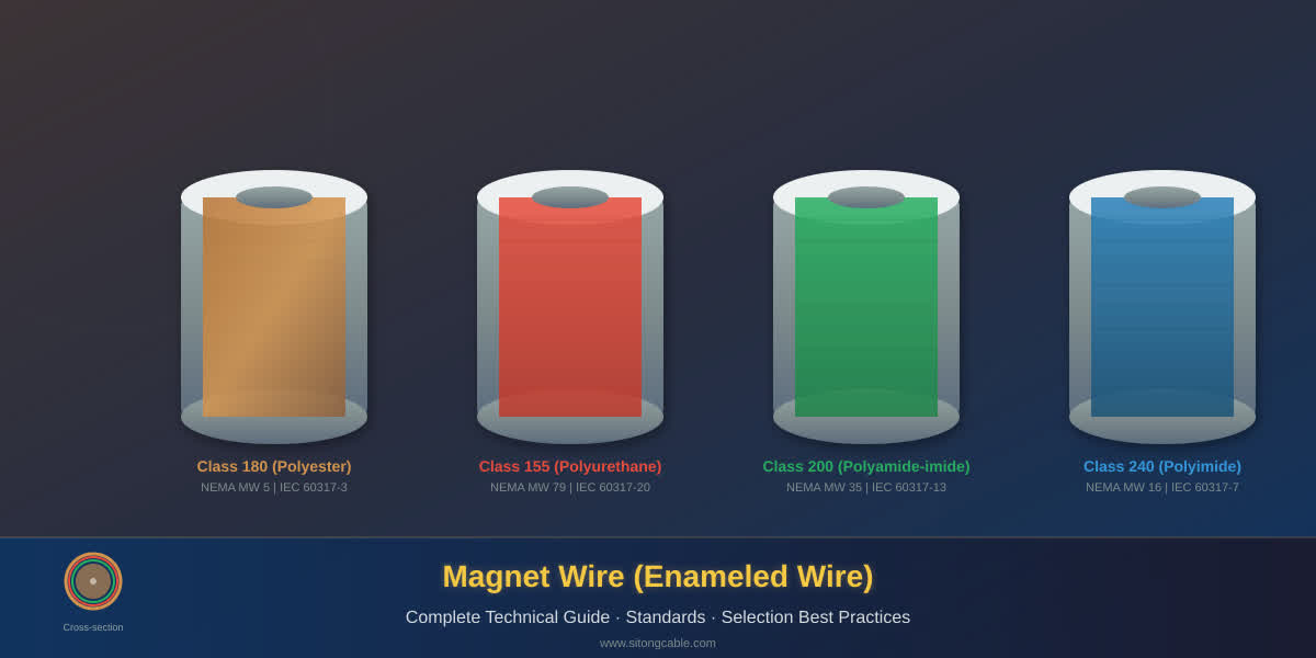
| IEC 60317 (series) | Enamelled winding wires | Round and rectangular magnet wire, various solderable and heat-resistant grades | Class 180 (H), Class 200 (N), Class 220 (R), Class 240 (S) |
| NEMA MW 1000 | Magnet wire (US adoption of IEC 60317 with additions) | Heavy-build, quadruple-build polyimide (ML), polyesterimide (PEI), self-bonding | Thermal class up to 240°C per MW 1000-C |
| MIL-W-22759 | Aerospace hookup wire | Solderable fluoropolymer insulated: ETFE (22759/32–35), PTFE (22759/11–13), PFA/FEP (22759/41–46) | 200°C (ETFE), 260°C (PTFE/PFA) continuous; 300°C intermittent |
| UL 5107 | Appliance & equipment wiring (US/UL) | Fluoropolymer, silicone rubber, PEEK-insulated single conductors, pairs, and coax | 150°C – 260°C depending on insulation; UL listing requires mandrel bend + dielectric |
| ISO 6722 | Road vehicle (automotive) cables | Thin-wall and standard-wall, single-core, unshielded, 60V–600V | Class A (85°C), B (100°C), C (125°C), D (150°C), E (175°C), F (200°C) |
💡 Tip: When specifying wire for dual-use (e.g., aerospace-derived sensor cable for industrial furnace), the governing standard is typically the more conservative one. MIL-W-22759 ratings often serve as a conservative baseline even for non-military applications due to their extensive qualification testing.
4. High Temperature Wire Types — Insulation & Conductor Specifications
The performance envelope of a high-temperature wire is dominated by the insulation material. Below, three tables classify commercially available constructions by insulation type, conductor options, and typical applications.
4.1 Fluoropolymer-Insulated Wires (150°C – 260°C)
| Code / Type | 🌡️ Temp Rating | Insulation Material | Conductor Options | Typical Applications |
|---|---|---|---|---|
| PTFE (Teflon™) solid/tape wrap | 260°C continuous, 300°C intermittent | Extruded or tape-wrapped PTFE (polytetrafluoroethylene) | Nickel-plated copper, silver-plated copper, nickel-clad copper | Aerospace fire zone, furnace sensor leads, downhole logging |
| PFA (perfluoroalkoxy) | 260°C continuous | Extruded PFA — melt-processable fluoropolymer | Silver-plated copper, bare copper, nickel-plated copper | Semiconductor equipment, chemical processing, high-purity applications |
| FEP (fluorinated ethylene propylene) | 200°C continuous | Extruded FEP — lower melt point than PTFE/PFA | Tinned copper, silver-plated copper | General appliance wiring, medical devices, flex applications at moderate temp |
| ETFE (ethylene tetrafluoroethylene) | 150°C – 200°C | Extruded ETFE — mechanically tough, radiation resistant | Silver-plated copper, nickel-plated copper, tin-coated copper | Aerospace hookup (MIL-W-22759/32), automotive (ISO 6722 Class F), nuclear |
4.2 High-Performance Polymer & Rubber-Insulated Wires (150°C – 250°C)
| Code / Type | 🌡️ Temp Rating | Insulation Material | Conductor Options | Typical Applications |
|---|---|---|---|---|
| PEEK (polyether ether ketone) | 250°C continuous, 300°C short-term | Extruded PEEK — exceptional chemical resistance & mechanical strength | Nickel-plated copper, stainless steel, silver-plated copper | Downhole oil & gas, medical implant lead wires, high-vibration/high-shock environments |
| Silicone Rubber (SiR) | 150°C – 200°C continuous, 250°C intermittent | Extruded silicone rubber, often with fiberglass braid jacket | Tinned copper, bare copper, nickel-plated copper | Flexible furnace leads, induction heating, appliance wiring in humid/corrosive environments |
| Cross-linked Polyolefin (XLPO) | 150°C – 180°C | Irradiation or chemically cross-linked polyolefin | Tinned copper, silver-plated copper | Automotive battery cables, traction motor leads, rail wiring |
4.3 Ceramic & Mica-Insulated Wires (250°C – 1000°C+)
| Code / Type | 🌡️ Temp Rating | Insulation Material | Conductor Options | Typical Applications |
|---|---|---|---|---|
| Mica tape + glass braid | 500°C – 600°C continuous | Phlogopite or muscovite mica tape, over-braided with fiberglass | Nickel-plated copper, stainless steel, Inconel alloy | Furnace heating element leads, steel mill ladle cables, fire-resistant circuits |
| Ceramic fiber insulated | 800°C – 1000°C+ | High-purity alumina-silica ceramic fiber braid or tape | Nickel-clad copper, stainless steel, Kanthal alloy | Thermocouple extension in kilns, burner management, high-temp oven wiring |
| Metallic-sheathed mineral insulated (MI) | 500°C – 1000°C | Compacted magnesium oxide (MgO) powder in SS/Inconel sheath | Copper, nickel-alloy, stainless steel conductors | Resistance temperature detector (RTD) leads, heater cables, nuclear sensors |
💡 Tip: For applications above 300°C continuous, fluoropolymer-only insulation is insufficient. Use mica tape (primary electrical barrier) plus ceramic braid (mechanical + thermal barrier) or fully mineral-insulated (MI) cable.
5. Selection Methodology — A 5-Step Engineering Process
Correct specification of high-temperature wire follows a systematic decision tree. We recommend the following five-step process:
Step 1: Define the Operating Temperature Profile
Determine three temperature parameters: - T_continuous: Maximum steady-state conductor temperature during normal operation. - T_intermittent: Peak temperature expected during transients (e.g., furnace door opening, engine afterburner). - T_ambient: The environment temperature surrounding the wire (may differ from conductor temperature due to self-heating).
Apply a safety margin: select wire with a continuous rating at least 25°C above T_continuous.
Step 2: Select the Conductor
Choose base metal and plating based on temperature and corrosion environment:
| Conductor | Max Useful Temp (continuous) | Plating Option | Best For |
|---|---|---|---|
| Copper (bare) | 150°C (oxidizes above) | — | Low-cost, low-temp applications |
| Tinned copper | 150°C (tin diffuses above) | Hot-dip tin | General appliance ≤ 150°C |
| Silver-plated copper | 200°C (silver tarnishes above) | Electrolytic silver | Aerospace, high-frequency; up to 200°C |
| Nickel-plated copper | 400°C (nickel stable) | Electrolytic nickel | Furnace, turbine, downhole — the most common high-temp choice |
| Nickel-clad copper | 450°C | Clad (bi-metal) | Extreme temp where oxidation resistance is critical |
| Stainless steel (304/316/Inconel) | 600°C – 800°C | — | Thermocouple extension, resistance heating alloys |
Step 3: Choose the Insulation System
Match insulation to the temperature profile from Step 1 using the tables in Section 4. Key trade-offs: - PTFE: Best electrical properties at high temp, but cold flow and notch-sensitive. Stripping requires specialized tooling. - PEEK: Highest mechanical strength and chemical resistance, but stiffer and more expensive. - Silicone rubber: Excellent flexibility down to −60°C, but poor abrasion resistance without braid. - Mica + ceramic: Necessary above 300°C, but bulky and limited flex life.
Step 4: Check Voltage and Current Ratings
⚠️ Voltage derating: High-temperature wire voltage ratings (typically 300V, 600V, or 1 kV for UL styles) are specified at rated temperature. At elevated temperatures, insulation resistance drops. Derate voltage by 0.5% per °C above 100°C as a rule of thumb.
For current-carrying capacity, use the conductor ampacity formula adjusted for temperature:
I = sqrt((T_max − T_ambient) / (R_ac × R_th))
where:
- T_max = maximum conductor temperature (°C)
- T_ambient = ambient temperature (°C)
- R_ac = AC resistance of conductor at operating temperature (Ω/m)
- R_th = thermal resistance of insulation + environment (°C·m/W)
For three-phase power applications:
I = P / (√3 × V × cos φ)
Then confirm the ampacity from the conductor manufacturer's standard tables at the elevated temperature.
Step 5: Verify the Environment
Check non-thermal stressors:
| Stressor | Key Consideration |
|---|---|
| Radiation | ETFE and PEEK are radiation-resistant (up to 200 Mrad); PTFE degrades above ≈ 10 Mrad |
| Chemical exposure | PEEK > PTFE > FEP > Silicone (oil resistance order) |
| Vibration/Shock | PEEK and ETFE have best mechanical toughness; PTFE can cold-flow under vibration |
| Moisture/Submersion | Mica absorbs moisture — must be sealed with silicone or jacket when submerged |
| Abrasion | Add glass braid, stainless steel braid, or metallic armor jacket |
6. Installation Practices for High Temperature Wire
Proper installation is critical to achieving the rated service life. High-temperature insulation materials behave differently from standard PVC or XLPE.
6.1 Minimum Bending Radius
- Fluoropolymer wires (PTFE, PFA, FEP): 10× cable outer diameter (OD) for static, 15× OD for dynamic/flex applications.
- PEEK-insulated wires: 8× OD static, 12× OD dynamic.
- Silicone rubber wires: 6× OD (flexible, but internal conductor can fail if bent sharply at cold temperatures).
- Mica/Ceramic wires: 12× OD minimum; repeated flexing damages the mica layer.
6.2 Stripping Considerations
- PTFE: Extremely slippery and notch-sensitive. Use hot-blade strippers (thermostrippers) for clean, crack-free end terminations. Avoid mechanical strippers with sharp V-blades that score the conductor.
- PEEK: Very stiff and tough. Use rotary strippers with carbide blades or laser stripping. Heat-assisted stripping improves results.
- Silicone rubber: Soft and easy to strip with standard tools, but the conductor may pull out of the insulation if the strip length is too long or the wire is under tension.
- Mica tape + braid: Stripping must be done in stages — cut and remove the outer braid, then unwrap or cut the mica tape, exposing the conductor. Expect some mica dust.
6.3 Termination Techniques
- Crimping: Use crimp terminals rated for the wire temperature (standard tin-plated terminals are limited to 150°C). For high-temp applications, use nickel-plated or stainless steel ring terminals with PTFE or silicone boots.
- Soldering: If soldering is required, use high-temperature solder (e.g., Sn95/Ag5, melting point 245°C). Note that the joint may creep above 150°C. For 200°C+, use crimped terminations exclusively.
- Screw terminals / barrier strips: Use nickel-plated brass or stainless steel hardware. Torque to manufacturer specification — overtightening can cold-flow PTFE insulation.
6.4 Heat Shrink Compatibility
Standard polyolefin heat shrink is unsuitable for high-temperature wiring. Use:
- PTFE heat shrink: 260°C rated, requires 330°C – 360°C installation temperature.
- FEP heat shrink: 200°C rated, requires 230°C – 250°C installation.
- PEEK heat shrink: 250°C rated, limited availability, requires specialized hot-air tools.
- Silicone rubber heat shrink: 200°C rated, flexible, suitable for splices in vibration-prone environments.
💡 Tip: Always pre-heat fluoropolymer heat shrink slowly. Rapid heating can cause air entrapment and voids under the shrink tubing.
7. Case Study: Thermocouple Sensor Cable for Industrial Furnace
Application: Type-K thermocouple extension cable for a natural-gas fired industrial annealing furnace operating at 200°C continuous with 300°C intermittent peaks during door-opening cycles.
Environment: Ambient heat radiation, occasional oil mist from hydraulic presses, and mechanical vibration from conveyor motors. Cable routing includes a 100 mm radius bend into a junction box on the furnace crown.
Selection Process:
- Temperature profile: T_continuous = 200°C, T_intermittent = 300°C (15 minutes per cycle). Applying the 25°C margin: minimum continuous rating = 225°C.
- Conductor: Nickel-plated copper (rated 400°C continuous) — chosen over silver-plated copper (200°C limit exceeded) and stainless steel (excessive resistance for thermocouple signal).
- Insulation: PTFE tape-wrapped and extruded (260°C continuous rating) with an outer fiberglass braid for abrasion resistance. PEEK was considered but rejected due to stiffness causing excessive stress at the 100 mm bend radius.
- Jacket: FEP or silicone rubber outer jacket not required; the fiberglass braid provides adequate mechanical protection in an indoor furnace environment. The PTFE primary insulation handles the 300°C intermittent peaks.
- Verification: Conductor resistance at 200°C (electrical) and 300°C (intermittent) confirmed within acceptable tolerance for Type-K signal transmission (±0.75% standard limits per IEC 60584-1).
Result: PTFE/fiberglass-braid Type-K extension wire with nickel-plated copper conductors, 20 AWG (7×28 stranding for flexibility), installed with 100 mm bend radius and nickel-plated ring terminals. Service life exceeded 5 years with no insulation failures.
8. Environmental & Durability Considerations
The following table summarizes environmental factors that affect high-temperature wire selection and the engineering rationale for each recommendation.
| ✅ Factor | 📋 Recommendation | 🔬 Rationale |
|---|---|---|
| Gamma / neutron radiation | Use ETFE or PEEK; avoid PTFE above 10 Mrad total dose | PTFE depolymerizes under radiation, evolving toxic HF gas. ETFE and PEEK crosslink and maintain integrity up to 200 Mrad. |
| Oil / hydrocarbon exposure | Select PEEK (best), PTFE (excellent), or FEP (good); avoid bare silicone rubber | Silicone swells and loses mechanical strength in hydrocarbons. PEEK is virtually inert to all organic solvents. |
| Concentrated acid / base | PTFE or PFA for extreme chemical resistance; PEEK degrades in concentrated sulfuric acid | PTFE is chemically inert to all common acids and bases at temperatures up to 260°C. |
| Continuous vibration (10–2000 Hz) | PEEK or ETFE; avoid PTFE unless mechanically supported | PTFE exhibits cold flow (creep) under sustained vibration, leading to insulation thinning and short circuits. Support PTFE with braid or conduit. |
| High humidity / condensation | Silicone rubber (excellent moisture barrier) or PEEK; seal mica/ceramic constructions | Mica is hygroscopic — absorbed moisture degrades insulation resistance. A silicone or FEP jacket over mica prevents moisture ingress. |
| UV / outdoor exposure | FEP or ETFE (excellent UV resistance); PTFE fair; silicone requires UV-stabilized formulation | Fluoropolymers inherently resist photo-degradation. Silicone requires carbon black or TiO₂ fillers for UV stability. |
| Thermal cycling (rapid) | PEEK or mica-based constructions; PTFE can develop micro-cracks after many cycles | Disparate thermal expansion coefficients between PTFE and copper can cause fatigue cracking at the insulation-conductor interface after 1000+ cycles from 25°C to 260°C. |
9. Frequently Asked Questions
Q1: What is the temperature limit of PTFE wire?
PTFE (polytetrafluoroethylene) is rated for 260°C continuous and 300°C intermittent (short-term, typically up to 30 minutes). The continuous rating is mandated by UL and MIL-W-22759 standards based on accelerated aging testing. Above 300°C, PTFE begins to depolymerize, releasing toxic perfluoroisobutylene (PFIB) gas.
Q2: How does PTFE compare to PEEK and silicone rubber for high-temperature wire?
| Property | PTFE | PEEK | Silicone Rubber |
|---|---|---|---|
| Max continuous temp | 260°C | 250°C | 200°C |
| Mechanical toughness | Poor (cold flow, notch-sensitive) | Excellent (highest tensile & abrasion) | Poor (low cut-through resistance) |
| Flexibility | Moderate | Low / stiff | Excellent (flexible to −60°C) |
| Chemical resistance | Excellent (inert) | Excellent (except strong acids) | Poor in hydrocarbons |
| Radiation resistance | Poor (>10 Mrad degrades) | Good (up to 200 Mrad) | Moderate |
| Relative cost | Moderate | High | Low |
Choose PTFE for maximum thermal and chemical resistance where mechanical support is available. Choose PEEK for high mechanical stress and chemical exposure up to 250°C. Choose silicone rubber for extreme low-temperature flexibility and moderate high-temperature performance at lowest cost.
Q3: What is the maximum voltage rating for high-temperature wire?
Standard ratings per UL 5107 and MIL-W-22759 are: - 300 V (light-wall, thin-wall constructions, typically 22–30 AWG) - 600 V (standard wall, most common for industrial 14–20 AWG) - 1 kV (heavy-wall, for power circuits and traction motor leads) - 2 kV+ (specialized, e.g., ignition wire, induction heating leads)
Voltage rating applies at the rated temperature. See derating guidance in Section 5, Step 4.
Q4: What is the minimum bending radius for PTFE high-temperature wire?
The general rule: 10× cable outer diameter (OD) for static installations and 15× OD for dynamic (flexing) applications. For example, a 2.5 mm OD PTFE wire requires a minimum bend radius of 25 mm static, 37.5 mm dynamic. Violating the minimum bend radius causes micro-cracking of the PTFE insulation, leading to dielectric failure.
Q5: Can high-temperature wire be stored for long periods?
Yes. High-temperature insulation materials — particularly fluoropolymers (PTFE, PFA, FEP, ETFE) and PEEK — are chemically stable and do not hydrolyze or oxidize during storage. Typical shelf life: - PTFE / PFA / FEP: Indefinite (decades) in a cool, dry environment away from UV and ozone. - PEEK: Indefinite. - Silicone rubber: 10–15 years (some plasticizer migration may stiffen the material). - Mica / ceramic: Indefinite, but keep sealed packaging to prevent moisture absorption in mica.
Q6: What are typical lead times for custom high-temperature wire?
Lead times depend on configuration: - Standard catalog items (UL 5107, MIL-W-22759, ISO 6722 stock sizes): 2–5 business days. - Custom stranding / plating / insulation thickness: 3–4 weeks. - Mica + ceramic constructions with special alloys: 6–8 weeks. - Mineral-insulated (MI) cable: 8–12 weeks.
Contact the Sitong Cable sales team (sales@sitongcable.com) for current lead time estimates on non-standard configurations.
Q7: What is the difference between "high temperature wire" and "fire-resistant cable"?
These are distinct classifications:
- High temperature wire: Rated for continuous operation at elevated temperatures (150°C–450°C+). The insulation remains functional indefinitely at the rated temperature.
- Fire-resistant (circuit integrity) cable: Designed to maintain circuit continuity for a defined period (e.g., 30, 60, 90 minutes) during a fire (typically at 750°C–950°C per BS 6387 or IEC 60331). It may not be rated for continuous high-temperature service.
Some constructions, such as mica-tape wrapped cables with ceramic braid, satisfy both requirements — continuous high-temperature operation and fire circuit integrity.
Q8: How do I select the correct stranding for high-temperature wire?
Stranding selection balances flexibility, current density, and termination reliability:
| Application | Recommended Stranding | AWG Equivalent Example |
|---|---|---|
| Fixed furnace wiring | Solid or 7-strand | 20 AWG solid or 7×28 |
| Moderate flex (junction box to sensor) | 19-strand | 20 AWG 19×32 |
| High flex (robot arm, moving carriage) | 41-strand or fine-strand (Type K) | 20 AWG 41×36 |
| Thermocouple extension | Solid (calibrated pair) | 24 AWG solid, Type K alloy |
For a given AWG, finer stranding increases flexibility but also increases DC resistance (up to 3% for 41-strand vs. solid) due to longer spiral path and inter-strand contact resistance.
10. Conclusion
High temperature wire selection is a multi-variable engineering decision that demands careful alignment of temperature profile, conductor metallurgy, insulation chemistry, and environmental stressors. By following the structured 5-step methodology outlined in this guide — and cross-referencing the material properties, standards compliance, and installation best practices provided — engineers can specify wire that delivers reliable service life measured in years rather than months.
For applications requiring custom constructions, non-standard conductor alloys, or rapid prototyping, the Sitong Cable engineering team offers design support, sample runs, and full type-test qualification per the applicable standards.
Explore the complete high-temperature wire product line: - High Temperature Wire Product Category - Contact Sitong Cable Engineering & Sales
📞 Phone: +86-371-69176007
📧 Email: sales@sitongcable.com
This guide was prepared by the Sitong Cable engineering team.