Armoured Cable (SWA) — Complete Technical Guide: IEC 60502, BS 5467 & BS 6724 Standards
Armoured Cable (SWA) — Complete Technical Guide: IEC 60502, BS 5467 & BS 6724 Standards
Steel wire armoured (SWA) cable is the standard choice for industrial power distribution, direct-buried feeders and utility networks wherever conductors need mechanical protection. The galvanized steel wire armour layer not only shields the cable from impact, rodents and ground movement — it also provides tensile strength during installation and can serve as the circuit protective conductor (CPC) under BS 7671. This guide covers armoured cable construction, types (SWA, AWA, STA), international standards, specification tables, a 5-step selection methodology, installation best practices and a project case study, with reference to IEC 60502, BS 5467, BS 6724, BS 6622 and IEC 60228.
1. What is an Armoured Cable? Construction and Working Principle
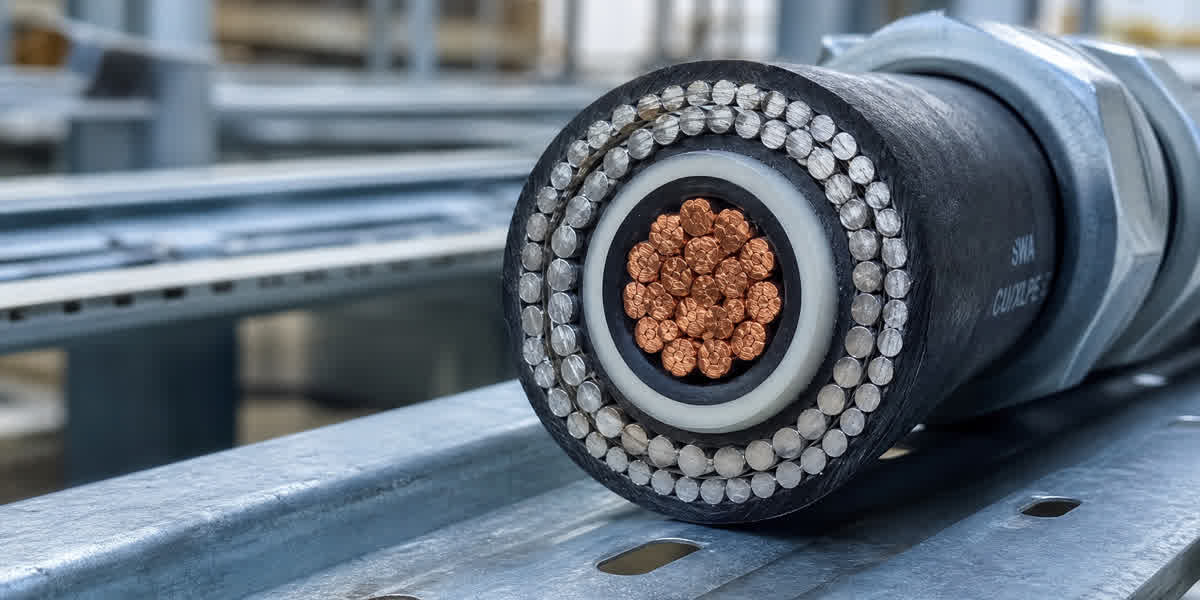
An armoured cable is a power cable with a metallic protection layer — usually galvanized steel wire or tape — laid between an inner bedding and an outer serving sheath. The armour is the defining element: it converts an ordinary power cable into a cable that can be buried directly, pulled through demanding routes, and left exposed in industrial environments.
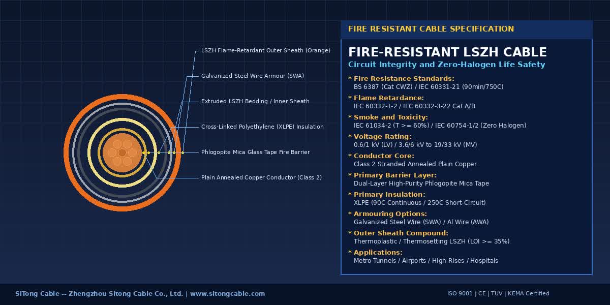
1.1 Layer-by-Layer Construction
| Layer | Function | Typical Material |
|---|---|---|
| Conductor | Carries current | Copper or aluminium, Class 1/2/5 per IEC 60228 |
| Insulation | Voltage withstand | XLPE (cross-linked polyethylene), EPR or PVC |
| Bedding | Cushions the armour, prevents insulation damage | PVC or LSZH compound |
| Armour | Mechanical protection + tensile strength + earthing path | Galvanized steel wire (GSW), aluminium wire (AWA) or steel tape (STA) |
| Serving (outer sheath) | Seals out moisture, provides final protection | PVC or LSZH compound (BS 6724) |
💡 Why bedding matters: the bedding must be thick enough that the armour wires do not press into the insulation when the cable is bent. BS 5467 specifies minimum bedding thickness for each armour wire diameter.
1.2 The Four Standard Armour Types
| Type | Armour | Best Application |
|---|---|---|
| SWA (Steel Wire Armoured) | Single layer of galvanized steel wires | Mains distribution, direct burial, industrial plants — the most common type |
| AWA (Aluminium Wire Armoured) | Aluminium alloy wires | Single-core AC circuits and high-current runs where steel would cause eddy-current heating |
| STA (Steel Tape Armoured) | Two steel tapes applied helically | Radial crushing protection — railways, roads, rodent-prone sites |
| DWA / Double-wire | Two layers of steel wires | Extra mechanical duty, long heavy pulls |
2. Armoured Cable Types and Application Overview
Armoured cables cover the whole low-voltage and medium-voltage spectrum, from 0.6/1 kV service feeders to 19/33 kV primary distribution circuits. The table below maps common applications to recommended constructions.
| Application | Voltage Class | Recommended Construction |
|---|---|---|
| Sub-distribution feeders, industrial plants | 0.6/1 kV | 3- or 4-core copper XLPE/SWA/PVC |
| Street lighting and road power | 0.6/1 kV | 2-core copper or aluminium, SWA |
| Pump stations and water treatment | 0.6/1 kV – 3.6/6 kV | Multi-core XLPE/SWA, PVC or LSZH |
| Wind farm collector networks | 6.35/11 kV – 12.7/22 kV | 3-core XLPE/SWA per IEC 60502-2 |
| Utility primary distribution | 19/33 kV | 3-core XLPE/SWA or AWA, BS 6622 |
| Control and instrumentation circuits | 300/500 V | Armoured control cable with screened pairs |
⚠️ Single-core rule: for single-core AC circuits above roughly 60 A, use AWA (aluminium wire armour) instead of SWA. Steel armour around a single AC conductor forms a magnetic circuit that heats up and derates the cable significantly.
3. International Standards Reference Table
| Standard | Title / Scope | Key Parameters |
|---|---|---|
| IEC 60502-1 | Power cables with extruded insulation, 1 kV–3 kV | Construction, test requirements, LV range |
| IEC 60502-2 | Power cables with extruded insulation, 6 kV–30 kV | MV range, partial discharge limits |
| BS 5467 | LV & MV cables with thermosetting insulation (XLPE) | The classic UK SWA specification, armour tables |
| BS 6724 | LSZH-sheathed cables with thermosetting insulation | Fire-safety version of BS 5467 (IEC 60332-3, IEC 60754, IEC 61034) |
| BS 6622 | MV cables 3.8/6.6 kV to 19/33 kV | MV SWA/AWA cables for utility networks |
| BS 7846 | LSZH fire-resistant cables | Circuit integrity + fire survival (enhanced fire performance) |
| IEC 60228 | Conductors of insulated cables | Conductor classes, resistance limits, stranding |
| ICEA S-95-658 | US power cable standard (NEC type TC) | US-market armoured constructions |
| UL 1277 | Type TC and TC-ER cables | US tray cable, armoured variants |
| IEEE 383 | Flame testing of cables | Fire propagation qualification |
| IEC 60332-3-24 | Flame spread on bunched cables | Category C vertical flame test |
| IEC 60754-1/-2 | Halogen acid gas evolution | Corrosivity of combustion gases (LSZH) |
| IEC 61034-2 | Smoke density measurement | Smoke emission of LSZH compounds |
| BS 7671 | IET Wiring Regulations (UK) | Installation, earthing of armour, bending radii |
| IEC 61914 | Cable cleats | Short-circuit force containment |
| IEC 62444 | Cable glands for electrical installations | Gland dimensions and tests |
💡 Project tip: European and Middle-East tenders typically specify BS 5467 or BS 6724 for LV and IEC 60502 for international projects; North American projects follow ICEA/UL construction requirements. Confirm the armour test regime (IEC 60332-3, IEC 60754, IEC 61034) when LSZH is mandated.
4. Construction Details and Specification Tables
4.1 Conductor Classes (IEC 60228)
| Class | Construction | Application |
|---|---|---|
| Class 1 | Solid round conductor | Small fixed installations |
| Class 2 | Stranded (circular, compacted or sector-shaped) | Standard power cables — most SWA cables |
| Class 5 | Fine stranded flexible | Flexible connections, panel droppers |
4.2 DC Resistance Limits (IEC 60228, Class 2 Copper)
| Nominal Area (mm²) | Max DC Resistance at 20 °C (Ω/km) | Typical SWA Application |
|---|---|---|
| 1.5 | 12.1 | Control circuits |
| 2.5 | 7.41 | Lighting, small motors |
| 16 | 1.15 | Sub-distribution feeders |
| 25 | 0.727 | Industrial feeders |
| 95 | 0.193 | Main distribution |
| 240 | 0.0754 | Large utility feeders |
4.3 Representative BS 5467 Armour Wire Sizing (Typical Values)
Full requirements are given in BS 5467 Table 12; the values below are typical for 0.6/1 kV multi-core XLPE/SWA/PVC cables.
| Nominal Conductor (mm²) | Approx. Diameter over Bedding (mm) | Armour Wire Ø (mm) | Typical No. of Wires |
|---|---|---|---|
| 4 × 2.5 | 13–15 | 1.25 | 14–16 |
| 4 × 16 | 19–22 | 1.6 | 18–22 |
| 4 × 25 | 23–26 | 2.0 | 20–24 |
| 4 × 95 | 35–39 | 2.5 | 28–32 |
| 4 × 240 | 52–58 | 3.15 | 36–42 |
💡 Selection note: armour wire diameter and count are set by the diameter over bedding, not by conductor size alone. When replacing a cable on an existing route, check the overall diameter against duct and gland sizes before ordering.
4.4 Approximate Ampacity — 3-Core XLPE/SWA/PVC, Copper (BS 7671 Method, Reference Conditions)
| Size (mm²) | Clipped Direct (A) | Buried Direct (A) | Voltage Drop (mV/A/m) |
|---|---|---|---|
| 4 × 16 | 88 | 74 | 2.8 |
| 4 × 25 | 110 | 92 | 1.75 |
| 4 × 95 | 270 | 210 | 0.52 |
| 4 × 240 | 480 | 350 | 0.21 |
⚠️ Derating factors (grouping, ambient temperature, soil thermal resistivity) per BS 7671 Appendix 4 / IEC 60364-5-52 must be applied. The buried values assume 1.5 K·m/W soil and 15 °C ground temperature.
5. Selection Methodology — 5 Steps
Step 1: Define the Electrical System
Voltage class (0.6/1 kV, 6.35/11 kV, etc.), earthing arrangement (TN-S, TN-C-S, TT), fault level, and whether the armour will be used as the CPC.
Step 2: Size the Conductor
S (mm²) = based on design current, voltage drop limit (typically ≤ 5% for feeders, ≤ 3% for final circuits), and fault withstand: S ≥ √(I²t)/k
For a 400 V feeder, 3-phase, 160 A load over 150 m with 5% drop limit: voltage drop per metre = 20 V / 150 m = 0.133 V/m = 133 mV/m ÷ √3 ≈ 77 mV/A/m per phase — from the table, 95 mm² (0.52 mV/A/m × 160 A × 1.732 × 150 m ≈ 21.6 V ≈ 5.4%) — recalculate at 120 mm² or accept 95 mm² with derating. Always check against the cable manufacturer's rating tables.
Step 3: Choose the Armour Type
- SWA — default for multi-core LV/MV, direct burial, industrial.
- AWA — single-core AC circuits, high-current single-phase runs.
- STA — where radial crushing (railway ballast, vehicle crossings) is the dominant risk.
- LSZH armour bedding/serving — confined spaces, tunnels, public buildings (BS 6724).
Step 4: Choose the Sheath Material
PVC (BS 5467) for general use; LSZH (BS 6724/BS 7846) where fire toxicity and smoke are a concern. For fire survival circuits (fire alarms, emergency lighting) use BS 7846.
Step 5: Verify the Installation Environment
Corrosion class (C4/C5 coastal → consider AWA or enhanced servings), burial depth (600 mm under soft ground, 900 mm under roads per BS 7671), glanding and cleating requirements, and pulling tension limits.
6. Installation Best Practices
6.1 Bending Radius
| Condition | Minimum Bend Radius |
|---|---|
| Installed, armoured cable | 6 × overall diameter |
| During pulling | 12 × overall diameter |
| At gland entries | 6 × OD, with straight lead-in ≥ 300 mm |
6.2 Glanding and Earthing the Armour
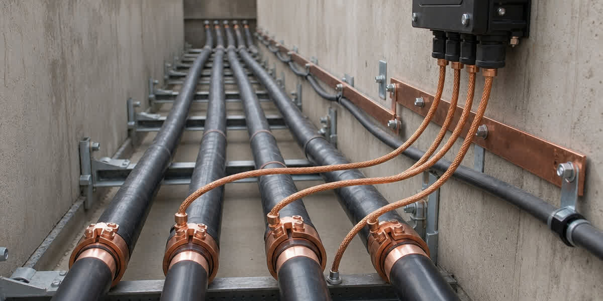
Use compression glands to BS 6121-1 / IEC 62444 with an armour clamp (banjo washer) that makes positive contact with the steel wires. Under BS 7671, the armour of a SWA cable is the CPC: terminate it at both ends with the gland earth tag bonded to the earthing conductor. The armour cross-sectional area must satisfy the fault-current withstand for the circuit.
| Gland Type | Application |
|---|---|
| BW (brass, CW) | Indoor, dry — standard SWA |
| CW (compound) | Outdoor / wet — filled for sealing |
| E1W/E1F | Hazardous areas (ATEX/IECEx) |
| E1U | Hazardous areas, gas groups IIA/IIB |
6.3 Direct Burial
Lay at ≥ 600 mm depth (900 mm under roads), on a 75 mm sand bed, with warning tape 150 mm above the cable. Do not pull directly against the armour — use a pulling stocking over the sheath and keep tension within the manufacturer's limit (typically ≤ 50 N/mm² of conductor cross-section).
6.4 Cable Cleating (Short-Circuit Forces)
Per IEC 61914, cleats must restrain the cable against the peak short-circuit force F = (0.17 × Ipk² × s) / d where Ipk is the peak fault current (kA), s the conductor spacing (m) and d the centre-line distance (m). Clamp single-core cables in trefoil to cancel magnetic forces.
7. Case Study — 11 kV Wind Farm Collector Network
| Parameter | Value |
|---|---|
| Route | 4.2 km, direct buried, rural terrain |
| Voltage | 6.35/11 kV |
| Load | 3-core, 95 mm² copper, 12 MW wind cluster |
| Standard | IEC 60502-2 / BS 6622 |
| Route hazards | Vehicle crossings ×3, waterlogged sections, rodent activity |
Option A — Unarmoured XLPE in ducts: cheaper cable, but requires 4.2 km of duct, 9 jointing/pull pits and full concrete encasement at crossings; installation labour roughly doubles.
Option B — 3-core XLPE/SWA: cable buried directly with sand bed and warning tape; armour provides mechanical protection and doubles as the earth continuity path; glands at both terminations with earth tags bonded to the earthing grid.
✅ Recommendation: Option B. The SWA construction eliminated the duct system (≈35% total-installed-cost saving), the armour withstood vehicle crossings without concrete protection, and the armour-to-earth bonding satisfied the utility's touch-voltage requirements. Site acceptance: insulation resistance ≥ 1 GΩ/km at 5 kV DC after installation, armour continuity ≤ 0.5 Ω.
8. Environmental and Durability Considerations
| Factor | Recommendation | Rationale |
|---|---|---|
| Coastal / C4-C5 corrosion | AWA or hot-dip galvanized wires with PVC serving intact | Galvanizing protects the steel; any exposed wire corrodes quickly in salt air |
| Waterlogged ground | PVC or PE serving, sealed glands | Moisture under the armour accelerates corrosion and partial discharge in MV |
| Rodents / termites | STA or SWA with tight serving | Metallic armour is the only reliable barrier |
| UV exposure | Keep black PVC serving; avoid prolonged sun on LSZH compounds | UV degrades many LSZH sheaths faster than PVC |
| Fire risk / confined spaces | LSZH per BS 6724 / BS 7846 | IEC 60332-3 flame spread, IEC 60754 low halogen, IEC 61034 low smoke |
| Vibration (pumps, compressors) | Flexible tail via Class 5 conductors + cleats at 300 mm pitch | Fatigue failure of solid/stranded conductors and armour wires |
9. FAQ
Q1: What does SWA stand for, and what is the difference between SWA and STA? SWA means steel wire armoured — a single layer of galvanized steel wires. STA means steel tape armoured — two helically applied steel tapes. SWA provides the best tensile strength and impact resistance; STA provides superior resistance to radial crushing and is common on railway and road-crossing installations.
Q2: Can SWA cable be buried directly underground? Yes — direct burial is the primary application. Lay at least 600 mm deep (900 mm under roads) on a sand bed, cover with warning tape, and use compound-filled glands at terminations so moisture cannot track under the armour.
Q3: Why is AWA cable used instead of SWA for single-core circuits? Steel armour around a single AC conductor forms a closed magnetic path, causing eddy-current and hysteresis heating that derates the cable and can overheat it. Aluminium wire armour (AWA) is non-magnetic, so single-core circuits above roughly 60 A should use AWA.
Q4: What is the minimum bending radius for SWA cable? 6 × the overall diameter when installed, and 12 × overall diameter while pulling. For a typical 4 × 25 mm² SWA cable at about 25 mm diameter, that means 150 mm installed and 300 mm during pulling. Tighter bends can permanently deform the armour wires.
Q5: How is the armour of a SWA cable earthed? Under BS 7671 the armour is the circuit protective conductor (CPC). Terminate the armour at both ends through a compression gland fitted with an earth tag (banjo), bonded to the earthing conductor. Verify the armour's cross-sectional area meets the fault-current withstand required for the circuit.
Q6: What is the difference between BS 5467 and BS 6724? BS 5467 covers XLPE-insulated armoured cables with PVC bedding and sheath. BS 6724 is the same cable family but with low-smoke, halogen-free (LSZH) bedding and sheath, meeting IEC 60332-3 flame spread, IEC 60754 halogen and IEC 61034 smoke requirements. Choose BS 6724 for tunnels, public buildings and confined spaces.
Q7: What voltage grades is SWA cable available in? Common grades are 0.6/1 kV (LV), 1.9/3.3 kV, 3.8/6.6 kV, 6.35/11 kV, 8.7/15 kV, 12.7/22 kV and 19/33 kV (MV, per IEC 60502-2 / BS 6622). The rating defines the insulation thickness, not the armour.
Q8: How do I choose the correct gland size for SWA cable? Measure the overall diameter of the cable over the serving. Select the gland whose size range covers that diameter (e.g., a 25 mm² 4-core cable at ~25 mm OD typically needs a 25S or 32S gland). The gland must also match the armour wire diameter so the clamp grips the wires securely.
10. References and Standards
| Standard | Description |
|---|---|
| IEC 60502-1/-2 | Power cables with extruded insulation, LV and MV |
| BS 5467 | Thermosetting-insulated armoured cables |
| BS 6724 | LSZH-sheathed armoured cables |
| BS 6622 | MV armoured cables 3.8/6.6 kV to 19/33 kV |
| BS 7846 | Fire-resistant LSZH cables |
| IEC 60228 | Conductor classes and resistance |
| IEC 60332-3 | Flame spread on bunched cables |
| IEC 60754 / IEC 61034 | Halogen and smoke emission |
| BS 7671 / IEC 60364-5-52 | Installation and cable sizing |
| IEC 61914 / IEC 62444 | Cable cleats and glands |
| ICEA S-95-658 / UL 1277 | North American tray cable |
11. About Sitong Cable
Zhengzhou Sitong Cable is a professional manufacturer of power cables, control cables, electric wires and overhead conductors, producing armoured constructions to IEC, BS, ASTM and ICEA standards with full type-test documentation. Our engineering team supports cable selection, glanding and installation queries for projects worldwide.
👉 Browse our power cable range or contact our team for armoured cable specifications, type tests and lead times.
This guide was prepared by the Sitong Cable engineering team. All technical data references the standards listed in Section 10; always verify final ratings with the cable manufacturer's data sheet.