Screened & Shielded Cable — Complete Technical Guide: EMC, Transfer Impedance & VFD Applications (IEC 60502, BS 5308, EN 50288 Standards)
Screened & Shielded Cable — Complete Technical Guide: EMC, Transfer Impedance & VFD Applications (IEC 60502, BS 5308, EN 50288 Standards)
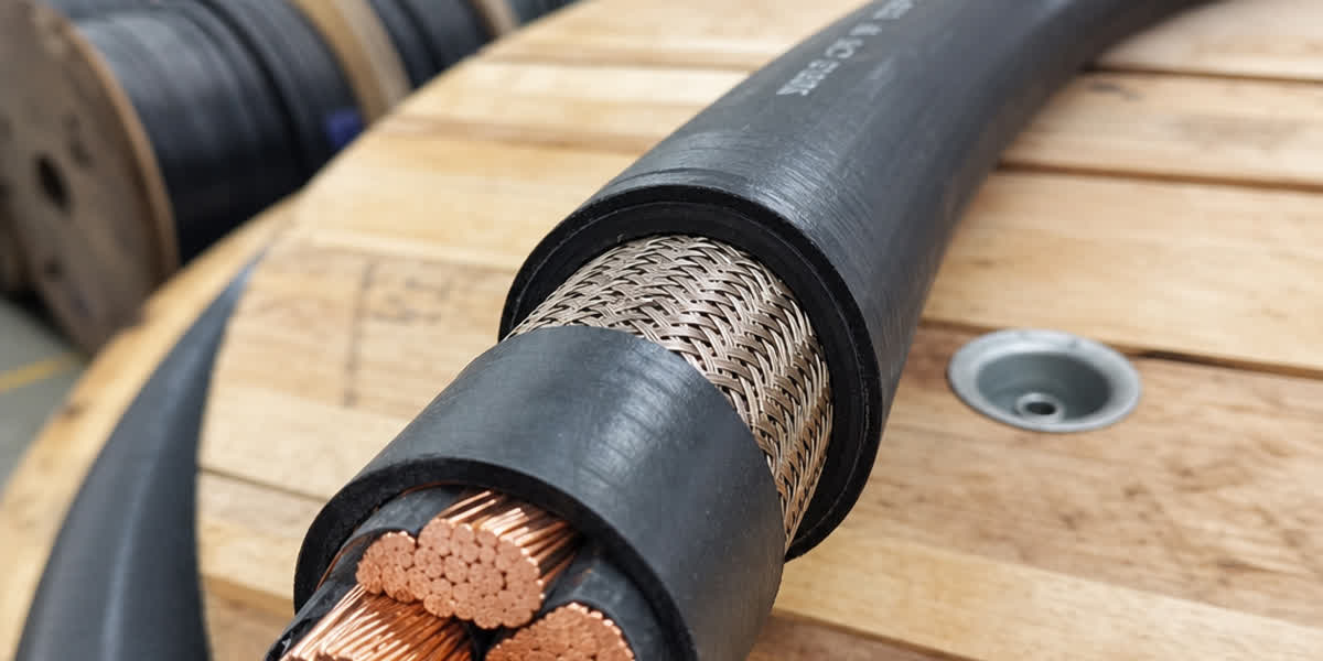
A screened (shielded) cable is an electrical cable in which the phase or signal conductors are surrounded by a conductive layer — a copper wire braid, copper tape, aluminium foil laminate, or concentric wire assembly — that intercepts electromagnetic interference (EMI) before it can couple into the circuit. Screening is one of the most misunderstood specifications in cable procurement: buyers routinely specify "screened" without defining coverage, transfer impedance, earthing philosophy, or the standard the screen must meet, and the resulting EMC failures cost far more than the cable itself. This guide is written for electrical engineers, panel builders and procurement professionals who need to specify screened power, control cable and instrumentation cable correctly for industrial, marine and utility installations.
We cover the physics of screening in plain engineering terms, the international standards that define screen performance (IEC 60502, BS 5308, EN 50288, ICEA S-73-532 and the IEC 61000 EMC family), a comparison of screen constructions with typical transfer-impedance values, a five-step selection methodology, special requirements for variable-frequency drive (VFD) feeders, installation and earthing best practice, a worked case study, and answers to the eight questions we hear most often from customers.
Why Screening Matters: The EMC Problem
Every current-carrying conductor radiates an electromagnetic field, and every conductor acts as an antenna that picks one up. In an industrial installation the offenders are well known: PWM variable-frequency drives switching at 2–16 kHz with rise times of 50–200 ns (generating interference well into the tens of MHz), contactors, welding plant, large motors on starting, and lightning transients on outdoor circuits. The victims are equally familiar: 4–20 mA analogue loops, RTD and thermocouple inputs, RS-485 and fieldbus links, and sensitive electronic instrumentation.
A screen performs three duties:
| Function | What it does | Typical application |
|---|---|---|
| Electrostatic (capacitive) shielding | Shunts capacitive-coupled noise to earth; effective from DC upwards | Instrumentation, signal circuits |
| Electromagnetic shielding | Attenuates magnetic-field coupling via induced shield currents | Motor feeders, VFD cables, cable trays with power + signal |
| Safety/earth continuity | Provides a defined low-impedance earth path; in concentric designs doubles as neutral/PEN | LV distribution, mines, marine |
The key rule: screening is only as good as its termination. A perfect screen with a 50 mm pigtail earth lead can be ten to a hundred times worse than an adequate screen bonded 360° around the gland, because the pigtail's inductance raises the transfer impedance at high frequency. We return to this in the installation section.
For most industrial sites the practical specification question is not "screened or unscreened" but which screen construction, what coverage, and how it is earthed — which is exactly what the standards in the next section define.
International Standards Reference Table
Screening performance is defined differently across jurisdictions, so the standard you specify should match the project's tender documents and the final installation location.
| Standard | Title / Scope | Key screening parameters |
|---|---|---|
| IEC 60502-1 | Power cables with extruded insulation, 1 kV (LV) | Screen/earth conductor sizing, concentric conductor options |
| IEC 60227 / IEC 60228 | PVC-insulated cables / conductor classes | Conductor classes 1–5, stranding rules |
| BS 5308 | Instrumentation cables (Part 1 PE, Part 2 PVC insulated) | Screen types: collective, individual + collective; coverage, drain wire, test voltages |
| EN 50288-1 / -7 | Multi-element metallic cables — general requirements / cables for variable frequency drives | Symmetric 3+3 construction, 100 % screen coverage for VFD |
| ICEA S-73-532 / NEMA WC 57 | Control cables (North America) | Braid coverage %, shield types |
| UL 13 / UL 1277 | Power-limited circuit cables / Type TC tray cable | Foil + drain wire, braid options, 600 V |
| IEC 61000-6-2 / -6-4 | EMC immunity / emission — industrial environments | Whole-installation EMC limits the cable system must support |
| IEC 61800-3 | Adjustable speed drive systems — EMC requirements | Motor cable screening requirements for drive compliance |
| IEC 62153-4-3 | Metallic communication cable test methods — surface transfer impedance (triaxial method) | The measurement standard for Zt |
| IEC 60332-1-2 / -3-24 | Flame propagation tests | Fire behaviour of screened cables |
| IEC 60754 / IEC 61034 | Halogen acid gas / smoke density | LSZH screen and sheath materials |
| IEEE 519 / IEEE 383 | Harmonics / industrial cable qualification | Drive-system harmonic limits; cable type tests |
| BS 7671 | IET Wiring Regulations | Earthing, segregation distances, screen earthing |
| IEC 62444 | Cable glands for electrical installations | EMC gland performance classes |
💡 Project tip: For European tenders specify EN 50288-7 for VFD feeders and BS 5308 for instrumentation; for North American projects use ICEA S-73-532 / NEMA WC 57 or UL 1277; for global plants the IEC 60502-1 + IEC 61000 combination is the most widely accepted baseline.
Screen Construction Types & Specifications
Screens are manufactured in five principal constructions. Coverage is expressed as a percentage of the underlying surface enclosed; braid coverage of 80–90 % is standard for control and power screens, while foil laminates achieve 100 % coverage by construction.
| Screen type | Construction | Typical coverage | Typical Zt @ 1 MHz | Best for |
|---|---|---|---|---|
| Copper wire braid | Interwoven tinned/bare copper wires over the cores | 80–90 % | 10–50 mΩ/m | General control, VFD, instrumentation |
| Double braid | Two counter-wound braids | 85–95 % | 1–5 mΩ/m | High-EMC industrial, marine |
| Copper tape (helical) | Wound copper tape with overlap | ~100 % (overlap dependent) | 5–15 mΩ/m | Power cables, MV, screened LV |
| Al/PET foil + drain wire | Aluminium metallised polyester laminate with tinned copper drain wire | 100 % (foil) | 50–150 mΩ/m | UL 13 signal circuits, digital comms |
| Combination (foil + braid) | Foil under a braid; drain wire for termination | 100 % + 85 % | 5–20 mΩ/m | Instrumentation, fieldbus, high-integrity signal |
| Concentric wires | Helically applied copper wires (often serving as neutral/PEN) | ~100 % | 1–5 mΩ/m | LV distribution — see our concentric cable range |
Values are indicative orders of magnitude; actual Zt depends on material, lay angle, wire diameter and termination method. Always request the manufacturer's measured values to IEC 62153-4-3 for critical applications.
💡 Selection note: do not judge a screen by coverage alone. A 100 % foil screen has a higher transfer impedance than an 85 % braid at most frequencies of interest because the foil's thin aluminium film carries shield current poorly; for power and VFD circuits a copper braid (or copper tape) is nearly always the better choice, with foil reserved for low-current digital and instrument circuits where termination simplicity matters.
Transfer Impedance & Screening Effectiveness
The single most useful number describing a screen is its surface transfer impedance:
Zt = V2 / (I1 × l)
where I1 is the current flowing on the screen, V2 is the voltage induced on the inner conductor, and l is the cable length. Zt is expressed in mΩ/m and is measured by the triaxial method of IEC 62153-4-3. The lower Zt, the better the screen — an ideal solid tube approaches a few µΩ/m; a poor foil-and-drain assembly can exceed 100 mΩ/m at 10 MHz.
Three practical consequences follow:
- Zt rises with frequency for braids and foils, so a screen that is "fine at 50 Hz" can be useless for a PWM drive with 100 ns edges. Specify Zt at the frequencies of interest, not just at mains frequency.
- Termination dominates. A pigtail earth lead adds inductance that raises effective Zt dramatically above ~1 MHz; a 360° EMC gland preserves the screen's rated performance (see installation section).
- Screening factor vs transfer impedance. The screening factor
k(shield current divided by total interference current) is used by some older specifications; Zt is the modern, measurable parameter and is what IEC 62153-4-3 and most EMC engineers now request.
Selection Methodology — 5 Steps
Step 1 — Define the signal and the EMC environment. Classify each circuit: analogue (4–20 mA, mV, thermocouple), digital (RS-485, Ethernet, fieldbus), or power (motor feeders, VFD, distribution). Then classify the environment: clean (control room), moderate (general plant), harsh (adjacent to drives, switchgear, welding), or severe (MV switchyards, marine, mining).
Step 2 — Choose the screen construction from the required Zt. Use the table above. Rule of thumb: analogue instrumentation → individual + collective braid per BS 5308; VFD feeders → 100 % coverage braid per EN 50288-7; digital comms → foil + braid combination; general power cable in mixed trays → copper tape or braid.
Step 3 — Size the conductors. Select cross-section from load current, voltage drop and short-circuit requirements per IEC 60228 classes 2 (power) or 5 (flexible). Derate for grouped installation — a screen adds no ampacity but the installation method usually reduces it.
Step 4 — Verify electrical parameters. For VFD cables check mutual capacitance (lower is better for common-mode leakage; typical screened VFD designs run 150–300 pF/m) and the L/R ratio of the symmetrical design (values close to 1.0 minimise circulating currents). For instrumentation cables check loop resistance and, where specified, crosstalk between pairs.
Step 5 — Specify the extras. Flame-retardant class (IEC 60332-3 category A/B/C), halogen-free / LSZH (IEC 60754, IEC 61034) for tunnels and public buildings, armouring for mechanical protection, and gland compatibility (IEC 62444 EMC glands).
VFD & Motor Feeder Cables
Variable-frequency drives are the single most common reason a plant discovers it needed screened cables. PWM inverters produce common-mode voltages with dv/dt of several kV/µs and switching frequencies of 2–16 kHz; the motor cable is both a radiator and a receiver, and unscreened feeders cause bearing currents, nuisance tripping of drives and corrupted adjacent signal circuits.
For VFD feeders specify:
- Symmetric 3+3 core construction — three phase conductors and three PE conductors of equal size arranged symmetrically. This cancels the zero-sequence magnetic field, reduces common-mode current, and gives a low L/R ratio. Asymmetric 3-core + earth designs do not.
- 100 % screen coverage — a tinned copper wire braid over the assembled cores, providing a low-impedance return path for common-mode current from the motor frame back to the drive.
- Screen area matched to phase conductors — the screen must carry common-mode current continuously, not just fault current; undersized screens overheat on long runs.
- Low mutual capacitance — to minimise capacitive leakage current, particularly on long runs above 100 m.
- Compliance with EN 50288-7 and IEC 61800-3 — the drive system's EMC declaration of conformity is only valid with the specified screened cable type and correct termination.
Installation & Earthing Best Practices
A technically perfect cable fails EMC if installed badly. The five rules that matter most:
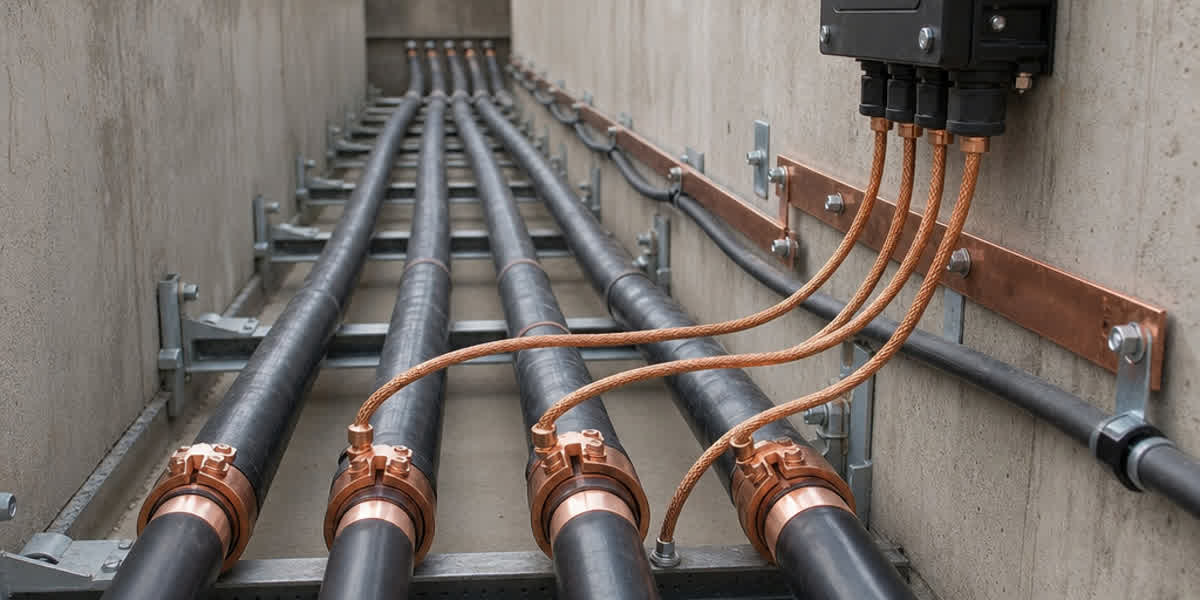
- Bond 360°, never pigtail, above ~1 MHz. Strip the screen back, fold it over the gland body and clamp with an IEC 62444 EMC gland so the braid contacts the gland 360°. A pigtail of even 50 mm raises effective Zt by an order of magnitude at VFD frequencies.
- Earthing philosophy depends on the circuit. For instrumentation (BS 5308): earth the screen at one end only (usually the control-room end) to avoid ground loops; the far end may be terminated via a capacitor or spark gap where lightning protection demands it. For VFD and power screens: earth at both ends (and at the motor end via the gland), because the screen carries common-mode current and must complete the circuit.
- Segregate by category. Keep power and signal circuits in separate trays; BS 7671 and NEC 725.136 practice calls for separation of at least 300 mm between power and sensitive signal cables, increasing with power level, with crossings at 90°.
- Respect bending radius. Screened cables are stiffer than unscreened; minimum bending radius is typically 6× OD for braid-screened cables (12× OD for armoured types) during installation, and double that for fixed termination in tight glands.
- Never use the screen as the sole protective earth. Screens provide EMC and fault-current paths, but a dedicated earth continuity conductor (or the concentric neutral, where applicable) must carry the PE function.
Case Study: Wastewater Treatment Plant, 16 × 75 kW VFD Pumps
A municipal plant reported intermittent drive trips and corrupted 4–20 mA level signals from its clarifier instrumentation. The original installation used 4-core unscreened power feeders laid 150 mm from the signal trays.
| Parameter | Original (faulty) | Redesigned |
|---|---|---|
| Motor feeders | 4-core unscreened, 150 mm from signal | EN 50288-7 3+3 screened VFD cable, 500 mm segregation |
| Instrumentation | Unscreened PVC | BS 5308 screened, individually screened pairs, single-point earthed |
| Glands | Standard | IEC 62444 EMC glands, 360° braid bonding |
| Signal noise floor | 8 % of span | < 0.5 % of span |
| Drive trips / month | 6–9 | 0 |
The redesign eliminated every trip and returned the analogue signals to instrument accuracy — with no change to the drives themselves. The lesson: screening selection and installation discipline, not more expensive drives, solved the EMC problem.
Environmental & Durability Considerations
| Factor | Recommendation | Rationale |
|---|---|---|
| Coastal / offshore | Tinned copper braid, LSZH sheath | Tinned conductors resist salt corrosion; braid remains the earth path |
| High temperature | Copper tape or braid with silicone/EPR insulation | Foil laminates degrade above ~105 °C |
| Vibration (machinery, marine) | Braid preferred over foil; proper gland strain relief | Braid withstands flexing; foil cracks and loses continuity |
| Fire risk (tunnels, high-rise) | IEC 60332-3 category C/A + IEC 60754/IEC 61034 LSZH | Halogen-free, low-smoke materials protect egress routes |
| Long outdoor runs | Screen plus overall sheath; UV-stable jacket | Sheath protects the braid from oxidation and abrasion |
FAQ
1. What is the difference between screened and unscreened cable? A screened cable has a conductive layer (braid, tape, foil or concentric wires) around its cores that intercepts electromagnetic interference and provides a defined earthing path. An unscreened cable relies on physical separation and installation discipline alone, which is rarely sufficient in industrial environments with drives and switchgear.
2. What is transfer impedance and why does it matter? Transfer impedance (Zt, in mΩ/m) quantifies how much of the current flowing on a screen couples into the inner conductors. Measured per IEC 62153-4-3, it is the definitive figure of merit for screening: lower Zt means better shielding. Always compare Zt at the frequencies of your interference, not at 50/60 Hz.
3. Braid or foil — which screen is better? For power, VFD and general control circuits, copper braid (80–90 % coverage) is better because it carries shield current with lower impedance. Foil (Al/PET) achieves 100 % coverage but has higher Zt and is best for low-current digital and instrument circuits where termination simplicity and drain-wire convenience matter.
4. Why do VFD cables need 3+3 symmetric construction and 100 % coverage? The symmetric three-phase + three-PE layout cancels the magnetic field of the phase currents and minimises common-mode current, while 100 % braid coverage provides a low-impedance path for that common-mode current back to the drive. Both are required for reliable operation and for the drive's IEC 61800-3 EMC compliance.
5. Should the screen be earthed at one end or both ends? Instrumentation screens are normally earthed at one end only (control-room end) to prevent 50 Hz ground loops; VFD and power screens are earthed at both ends because they must carry common-mode current. When in doubt, follow the standard the cable was specified to (BS 5308 for instruments, EN 50288-7/IEC 61800-3 for drives).
6. Can I use a standard unscreened power cable for a VFD connection? Only for very short runs (< 10 m) in benign environments, and even then drive manufacturers will typically void the EMC warranty position. Long unscreened VFD feeders cause bearing currents, drive nuisance trips and radiated interference. Use a purpose-built screened VFD cable.
7. What is the difference between a screen and an armour? A screen is an electrical function — it carries interference and fault currents and controls EMC. Armour is a mechanical function — steel wire or tape that protects the cable from crushing and rodent attack. Many cables have both; the screen is inside, the armour outside the sheath. Do not use armour as an EMC screen.
8. How do I verify a screen's performance? Request the manufacturer's measured transfer impedance to IEC 62153-4-3, verify braid coverage (80–90 % for braid, 100 % for foil), check DC screen resistance, and after installation test screen continuity and insulation. For critical sites, commissioning EMC measurements per IEC 61000-6-2/-6-4 confirm the whole installation.
Conclusion
Screening is a system property, not a component option: the cable, its glands, its earthing philosophy and its segregation from other circuits must be designed together. Specify the standard (IEC 60502-1, BS 5308, EN 50288-7 or ICEA S-73-532) that matches your tender, choose the screen construction by transfer impedance rather than coverage alone, earth instrumentation screens at one end and VFD screens at both, and bond every screen 360° at the gland.
SiTong Cable manufactures screened and unscreened control cables, power cables and concentric cables to IEC, BS, EN and ICEA standards, with braid, tape, foil and concentric screen options, LSZH and flame-retardant variants, and full test documentation including transfer-impedance data on request.
👉 Browse our Control Cable product range 👉 Browse our Power Cable product range 👉 Contact our team
📬 Sales inquiries: sales@sitongcable.com | 📞 Phone: +86-371-69176007
This guide was prepared by the SiTong Cable engineering team. All technical data references the standards listed above; indicative values must be verified against the manufacturer's test certificate for critical applications.