ACAR Conductor: Complete Technical Guide — Standards, Specifications & Selection
ACAR Conductor: Complete Technical Guide — Standards, Specifications & Selection
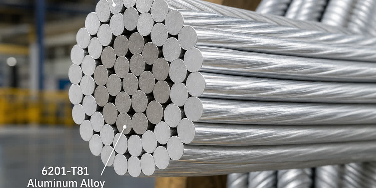
ACAR (Aluminum Conductor Alloy Reinforced) is a high-performance overhead conductor that combines concentric-lay stranded 1350-H19 aluminum wires with one or more layers of 6201-T81 aluminum-alloy wires to achieve a superior strength-to-weight ratio and higher conductivity than conventional ACSR conductors of equivalent diameter. Developed as an optimized alternative for medium-to-long-span transmission lines where both electrical efficiency and mechanical strength are critical, ACAR has become the preferred choice for 69 kV to 345 kV transmission projects, river-crossing spans, and coastal or industrial-corrosion environments where galvanized steel reinforcement is undesirable.
This guide provides a comprehensive technical reference for ACAR conductors, covering standard specifications, mechanical and electrical properties, construction variants, ampacity calculation methods, installation best practices, and comparison with alternative overhead conductor types.
1. Introduction
ACAR conductors fill a specific niche in overhead transmission line engineering: they offer higher conductivity than ACSR (because the reinforcement strands themselves carry current), while retaining mechanical strength comparable to ACSR (typically 85–95% of equivalent ACSR). The key distinction lies in the reinforcement material — instead of galvanized steel, ACAR uses high-strength 6201-T81 aluminum alloy, an Al-Mg-Si alloy that provides approximately twice the tensile strength of EC-grade (1350) aluminum while maintaining roughly 52.5% IACS conductivity.
The development of ACAR conductors in the 1960s and 1970s was driven by the need for a conductor that could: - Carry higher current than equivalent-diameter ACSR without requiring heavier towers - Resist corrosion in marine and industrial environments where galvanized steel would degrade - Provide lower electrical losses for long transmission distances - Maintain adequate sag characteristics for medium-to-long spans
Today, ACAR is standardized under ASTM B524 (USA), IEC 61089 (international), BS EN 50183 (European), and AS/NZS 3607 (Australia/New Zealand), with widespread adoption in North America, the Middle East, Southeast Asia, and Australia.
2. ACAR Conductor Construction
2.1 Layer Configuration
ACAR conductors are concentrically stranded, with the central core and one or more intermediate layers composed of 6201-T81 alloy wires, and the outer layer (or layers) composed of 1350-H19 aluminum wires. Common configurations include:
| Configuration | Core (Alloy) | Inner Layer(s) | Outer Layer(s) | Typical AWG/kcmil Range |
|---|---|---|---|---|
| 6/1 | 1× 6201-T81 | — | 6× 1350-H19 | 4 AWG – 4/0 AWG |
| 15/4 | 7× 6201-T81 | — | 15× 1350-H19 | 266.8 – 795 kcmil |
| 22/7 | 7× 6201-T81 | 15× 6201-T81 | 22× 1350-H19 | 795 – 1500 kcmil |
| 37/8 | 7× 6201-T81 | 15× 6201-T81 | 37× 1350-H19 | 1500 – 2500 kcmil |
Note: The notation "22/7" means 22 aluminum wires in the outer layer and 7 alloy wires in the core/inner layers. The total number of alloy strands divided by total strands gives the alloy-to-aluminum ratio, which directly correlates with mechanical strength.
2.2 Material Properties
| Property | 1350-H19 (EC Grade) | 6201-T81 (Alloy) |
|---|---|---|
| Elemental composition | ≥99.50% Al | Al + 0.6–0.9% Mg + 0.5–0.9% Si |
| Minimum tensile strength | 186 MPa (27 ksi) | 317 MPa (46 ksi) |
| Conductivity (% IACS) | 61.2% | 52.5% |
| Density | 2.705 g/cm³ | 2.703 g/cm³ |
| Coefficient of linear expansion | 23.0 × 10⁻⁶ /°C | 23.0 × 10⁻⁶ /°C |
| Modulus of elasticity | 69 GPa | 69 GPa |
💡 Key insight: The modulus of elasticity and thermal expansion coefficient of 1350 aluminum and 6201 alloy are nearly identical, which means ACAR conductors experience minimal differential thermal stress — a significant advantage over ACSR (steel core) where the steel/aluminum mismatch causes internal compressive forces.
3. International Standards Reference
ACAR conductors must comply with one or more of the following standards depending on the project jurisdiction:
| Standard | Scope | Key Requirements |
|---|---|---|
| ASTM B524 | Standard Specification for Concentric-Lay-Stranded Aluminum Conductors, Aluminum-Alloy Reinforced (ACAR) | 1350-H19 wires per ASTM B230/B609, 6201-T81 wires per ASTM B398/B399; stranding tolerances, tensile, and resistivity |
| IEC 61089 | Round wire concentric lay overhead electrical stranded conductors | Generic standard covering AAC, AAAC, ACSR, ACAR; Annex A provides ACAR-specific construction tables |
| BS EN 50183 | Conductors for overhead lines — Aluminium-magnesium-silicon alloy wires | European standard for the 6201-T81 alloy component |
| AS/NZS 3607 | Aluminium alloy stranded conductors for overhead power lines | Australian/New Zealand adoption; includes characteristic load tables |
| CSA C49.1 | Aluminum Alloy Stranded Conductors | Canadian standard; similar to ASTM B524 with metric sizing |
Key Testing Requirements per ASTM B524
| Test | Requirement | Frequency |
|---|---|---|
| Tensile strength (complete conductor) | ≥ 90% of calculated nominal | Every 500 km or production lot |
| Resistivity (1350-H19 wires) | ≤ 0.028264 Ω·mm²/m at 20°C | Per coil |
| Resistivity (6201-T81 wires) | ≤ 0.032757 Ω·mm²/m at 20°C | Per coil |
| Mass per unit length | ±2% of nominal | Every 500 km |
| Diameter tolerance | ±1% for individual wires | Per layer |
4. ACAR vs Alternative Overhead Conductors
4.1 Comprehensive Comparison
| Property | ACAR (22/7) | ACSR (26/7) | AAAC (all 6201) | AAC (all 1350) |
|---|---|---|---|---|
| Construction | Al + Al-alloy strands | Al + steel core | All-alloy strands | All aluminum strands |
| Conductivity (% IACS) | ~56% (weighted average) | ~51–55% (steel non-conductive) | 52.5% | 61.2% |
| DC resistance (Ω/km @ 20°C) | 0.0458 | 0.0512 | 0.0497 | 0.0419 |
| RTS (kN) | 185 | 215 | 198 | 125 |
| Weight (kg/km) | 1,420 | 1,340 | 1,390 | 970 |
| Strength-to-weight ratio | 130 N·m/kg | 160 N·m/kg | 142 N·m/kg | 129 N·m/kg |
| Corrosion resistance | Excellent | Moderate (steel core) | Excellent | Excellent |
| Typical span (m) | 250–400 | 300–500 | 250–400 | 150–300 |
| Relative cost per km | 1.0× (baseline) | 0.85× | 0.95× | 0.75× |
Values shown for a representative 795 kcmil conductor (approx. 403 mm² total area).
4.2 Decision Matrix: When to Choose ACAR
| Scenario | Recommended Conductor | Rationale |
|---|---|---|
| Short span (< 200 m), low icing | AAC | Lowest cost, highest conductivity |
| Standard transmission (200–400 m span) | ACAR | Best balance of strength & conductivity |
| Long span (> 400 m), heavy ice or wind | ACSR | Highest strength (steel core) |
| Coastal / industrial corrosion zone | ACAR or AAAC | No steel to corrode |
| Reconductoring existing towers (load-limited) | ACAR | Higher capacity without tower upgrade |
| Very long span (> 600 m), river crossing | ACSR (EHS core) or ACSS | Special high-strength constructions |
| Low-loss long-distance transmission | ACAR | Lower resistance than ACSR of same diameter |
💡 Tip: ACAR often provides the most economical solution when reconductoring existing lines where tower loading is constrained but increased ampacity is required. Because ACAR is lighter than ACSR of the same diameter, existing towers and foundations can typically be retained.
5. Mechanical & Electrical Properties
5.1 Rated Tensile Strength (RTS)
The rated tensile strength of an ACAR conductor is the sum of the rated strengths of its individual component wires, calculated per ASTM B524:
RTS = (N_al × σ_al × A_al) + (N_ay × σ_ay × A_ay)
Where:
- N_al, N_ay = number of 1350-Al and 6201-alloy wires
- σ_al, σ_ay = minimum tensile strength of individual wires (186 MPa / 317 MPa)
- A_al, A_ay = cross-sectional area of individual wires
Typical RTS values for common sizes:
| Size (kcmil) | Configuration | Total Area (mm²) | Alloy Wires | RTS (kN) | DC Resistance at 20°C (Ω/km) |
|---|---|---|---|---|---|
| 266.8 | 15/4 | 135.2 | 4 | 45.2 | 0.2131 |
| 336.4 | 15/4 | 170.5 | 4 | 57.1 | 0.1691 |
| 397.5 | 15/4 | 201.4 | 4 | 67.4 | 0.1431 |
| 477 | 15/4 | 241.7 | 4 | 81.0 | 0.1213 |
| 556.5 | 15/4 | 281.9 | 4 | 94.4 | 0.1039 |
| 636 | 22/7 | 322.3 | 7 | 107.8 | 0.0905 |
| 795 | 22/7 | 402.9 | 7 | 134.8 | 0.0724 |
| 954 | 22/7 | 483.4 | 7 | 161.7 | 0.0604 |
| 1033.5 | 37/8 | 523.7 | 8 | 175.3 | 0.0557 |
| 1272 | 37/8 | 644.5 | 8 | 215.8 | 0.0453 |
5.2 Ampacity Calculation
The current-carrying capacity of ACAR conductors follows the general heat-balance equation per IEEE Standard 738 (Standard for Calculating the Current-Temperature of Bare Overhead Conductors):
I = sqrt( (q_c + q_r − q_s) / R(T_c) )
Where:
- q_c = convective heat loss (W/m)
- q_r = radiated heat loss (W/m)
- q_s = solar heat gain (W/m)
- R(T_c) = conductor AC resistance at operating temperature (Ω/m)
Typical ampacity values at key assumptions (solar = 1000 W/m², emissivity = 0.5, absorptivity = 0.5, ambient temp = 40°C):
| Conductor Size | 75°C (kA) | 100°C (kA) | 125°C (kA) |
|---|---|---|---|
| 266.8 kcmil (15/4) | 0.43 | 0.54 | 0.62 |
| 397.5 kcmil (15/4) | 0.55 | 0.70 | 0.81 |
| 636 kcmil (22/7) | 0.74 | 0.94 | 1.10 |
| 795 kcmil (22/7) | 0.85 | 1.08 | 1.27 |
| 1033.5 kcmil (37/8) | 1.00 | 1.29 | 1.52 |
| 1272 kcmil (37/8) | 1.14 | 1.47 | 1.73 |
⚠️ Note: Ampacity values are indicative. Always perform site-specific calculations per IEEE 738 or IEC 61597, accounting for actual ambient temperature, wind speed, solar radiation, and conductor age.
5.3 Sag and Tension Characteristics
ACAR conductors exhibit sag behavior between AAC and ACSR. The following table compares sag at a representative 300 m span with initial and final (after 10-year creep) conditions:
| Conductor (795 kcmil) | Initial Sag at 50°C (m) | Final Sag at 50°C (m) | Initial Sag at 100°C (m) | Final Sag at 100°C (m) |
|---|---|---|---|---|
| AAC (all 1350) | 6.8 | 7.9 | 9.4 | 10.5 |
| ACAR 22/7 | 6.1 | 6.9 | 8.3 | 9.1 |
| AAAC (all 6201) | 5.8 | 6.5 | 7.9 | 8.6 |
| ACSR 26/7 | 5.4 | 5.9 | 7.2 | 7.7 |
Assumptions: 20% RTS initial tension, NESC Heavy loading district.
6. Accessories & Installation
6.1 Recommended Hardware
| Component | Recommendation | Notes |
|---|---|---|
| Suspension clamps | Aluminum-alloy (cast 356-T6 or similar) | Galvanized steel clamps contact aluminum wires → galvanic corrosion |
| Tension clamps (dead-ends) | Full-tension aluminium alloy dead-ends (preformed helical type or compression type) | Must be rated for 100% RTS of the conductor |
| Vibration dampers | Spiral vibration dampers (Stockbridge type) | Required for spans > 200 m or where Aeolian vibration is expected |
| Spacers | Aluminum alloy (for bundled conductor configurations) | Used for 2-conductor or 4-conductor bundle arrangements |
| Armor rods | Aluminum-clad steel or alloy rods at suspension points | Prevent fretting at support points |
| Jumper/connection hardware | All-aluminum or bimetal (Al-Cu) connectors | Avoid direct copper-to-aluminum contact without bi-metal transition |
6.2 Installation Guidelines
Stringing tension: - Initial stringing tension: 15–20% of RTS (typical) - Maximum stringing tension: 35% of RTS (limit for normal conditions) - Maximum ice/wind loading tension: 60% of RTS
Minimum bending radius during stringing: - Sheave diameter: ≥ 20× conductor diameter (recommended) - Minimum bend radius for compression dead-ends: 10× conductor diameter
Compression dead-end installation: 1. Strip the conductor to the specified length (no wire damage) 2. Clean aluminum surfaces with a stainless steel brush 3. Apply oxide-inhibiting compound (Al–Zn based, per ASTM B887) 4. Insert the conductor into the dead-end sleeve 5. Crimp using the manufacturer-specified die sequence and hydraulic pressure 6. Verify crimp dimensions with a go/no-go gauge
Sagging method: - Pre-stretch: Apply 50% RTS for 1 hour to remove constructional stretch (optional, reduces final creep) - Final sag: Set at the specified sag value at the ambient stringing temperature - Check with sag calculation tables specific to the conductor's tension-temperature equation
6.3 Corrosion Protection
| Environment | Recommended Protection | Standard |
|---|---|---|
| Coastal (≤ 5 km from sea) | ACAR preferred over ACSR; all-aluminum hardware | IEC 60865, IEEE 1243 |
| Industrial (chemical/acid) | ACAR or AAAC; sealed dead-ends | — |
| High humidity (> 80% RH annual avg) | Oxide-inhibiting compound on all connections | ASTM B887 |
| Agricultural (ammonia/fertilizer) | ACAR or AAAC; avoid steel entirely | — |
💡 Tip: The absence of steel in ACAR makes it inherently superior to ACSR in corrosion-prone environments. For severe coastal conditions, specify fully-sealed ACAR with the oxide-inhibiting compound pre-applied to the core interstices during stranding.
7. Case Study: Reconductoring a 132 kV Coastal Line with ACAR
Background
A 132 kV transmission line in Fujian Province, China, running parallel to the coast for approximately 35 km, was originally constructed in 1998 using ACSR 477 kcmil (15/4) conductors. After 25 years of service, periodic inspections revealed significant corrosion of the steel cores in sections within 2 km of the coastline. Zinc coating on the steel strands had been depleted, and red rust was visible on the core of several spans. The utility decided to reconductor rather than rebuild.
Requirements
| Parameter | Value |
|---|---|
| Original conductor | ACSR 477 kcmil (26/7) |
| Replacement conductor | ACAR 477 kcmil (15/4) |
| Span length (typical) | 250–350 m |
| Ambient temperature | −5°C to 40°C |
| Maximum conductor temperature | 100°C |
| Ice load | 5 mm radial |
| Wind load | 35 m/s (3-second gust) |
| Design life | 30 years |
| Tower loading constraint | No tower reinforcement permitted |
Selection Analysis
-
Corrosion: ACAR was selected over ACSR because the coastal environment had already proven destructive to galvanized steel. AAAC was also considered but rejected because the existing towers were designed for the higher weight of ACSR/ACAR and the lighter AAAC would have required tower modification to maintain clearance in high wind.
-
Electrical: ACAR 477 kcmil offers DC resistance of 0.1213 Ω/km at 20°C — approximately 5% lower than the original ACSR. This reduces I²R losses by approximately 12,000 kWh per year over the 35 km line (at 60% average loading), yielding a net present value saving of over $180,000 over 30 years.
-
Mechanical: The ACAR replacement has nearly identical weight (1,320 kg/km vs 1,310 kg/km for the original ACSR), so tower loading remained within original design margins. Sag at maximum load is only 2% greater than the original ACSR, well within clearance limits.
Result
The reconductoring was completed in 2023 with a 6-week outage window. The new ACAR 477 kcmil (15/4) conductors were installed using the existing towers and hardware — no tower reinforcement or foundation work was required. Post-commissioning thermal imaging confirmed uniform current distribution across all strands. The projected 30-year life with no steel corrosion risk provides significant maintenance cost savings compared to a comparable ACSR line in the same environment.
8. Environmental and Sustainability Considerations
| Factor | ACAR Benefit |
|---|---|
| Recyclability | 100% recyclable. Both 1350 and 6201 alloys are standard aluminum scrap grades with established recycling streams. Recycling aluminum consumes 95% less energy than primary production. |
| Corrosion longevity | No steel → no rust → fewer replacements. Expected service life of ACAR in non-coastal environments exceeds 50 years. |
| End-of-life value | The recovered conductor retains significant scrap value (aluminum content), offsetting decommissioning costs. |
| Carbon footprint | Lower transmission losses (higher conductivity than ACSR) reduce operational carbon emissions over the line's lifetime. |
| No galvanizing waste | Steel core galvanizing involves zinc and flux chemicals; eliminating steel eliminates this waste stream. |
9. Frequently Asked Questions
Q1: What is the difference between ACAR and AAC?
AAC (All Aluminum Conductor) consists entirely of 1350-H19 aluminum wires. ACAR replaces some of those wires with 6201-T81 aluminum-alloy reinforcing strands. The result: ACAR has approximately 50% higher tensile strength than equivalent AAC, making it suitable for longer spans and higher loading conditions while retaining good conductivity (approximately 56% IACS vs 61.2% for AAC).
Q2: Is ACAR stronger or weaker than ACSR?
ACSR typically has 15–30% higher RTS than equivalent-diameter ACAR, depending on the steel core proportion and steel grade. However, ACAR's strength-to-weight ratio is competitive because ACAR is lighter. For many applications (250–400 m spans), ACAR provides adequate strength with lower electrical losses than ACSR.
Q3: Which is more corrosion-resistant, ACAR or ACSR?
ACAR is significantly more corrosion-resistant in coastal, industrial, and agricultural environments. ACSR's galvanized steel core is vulnerable to corrosion when the zinc coating is depleted (typically 15–30 years in marine environments). ACAR contains no steel — both the 1350 and 6201 alloys are inherently corrosion-resistant aluminum.
Q4: Can ACAR be installed on existing ACSR-design towers?
Often yes. ACAR of the same kcmil rating typically has similar or slightly lower weight than equivalent ACSR. However, the lower tensile strength of ACAR may require adjustments to tension settings. Always perform a tower loading analysis before reconductoring.
Q5: How is ACAR different from AAAC?
AAAC (All Aluminum Alloy Conductor) uses 6201-T81 alloy for ALL strands — no 1350-H19 wires. ACAR uses a mix of 1350 and 6201. AAAC offers the highest strength of the all-aluminum options but has lower conductivity (52.5% IACS for all strands). ACAR achieves a better conductivity-strength balance by using pure aluminum in the outer (lowest-stress) layers.
Q6: Does ACAR require special hardware compared to ACSR?
Yes. Because ACAR contains no steel, all hardware that contacts the conductor must be aluminum or aluminum-alloy to prevent galvanic corrosion. Steel suspension clamps used for ACSR cannot be reused with ACAR. Hardware manufacturers provide ACAR-specific dead-ends, suspension assemblies, and compression fittings.
Q7: What is the maximum operating temperature of ACAR?
ACAR uses the same 1350-H19 and 6201-T81 wires as standard overhead conductors. Typical maximum continuous operating temperatures are: - 75°C (traditional limit for anneal-sensitive conductors) - 100°C (common high-temperature rating with normal hardware) - 125°C (limited to specialized high-temperature hardware and tension/compression fittings) - 150°C (with high-temperature rated fittings; requires creep and annealing evaluation)
Above 100°C, a permanent loss of tensile strength occurs due to annealing of the 1350-H19 wires (approximately 10–15% loss at 125°C over conductor lifetime). Evaluate the impact on sag and clearance before specifying high-temperature operation.
Q8: What international standards govern ACAR manufacturing?
ACAR conductors are primarily governed by ASTM B524 (USA), IEC 61089 (international), BS EN 50183 (European), AS/NZS 3607 (Australia/New Zealand), and CSA C49.1 (Canada). The component wires follow ASTM B230 (1350-H19) and ASTM B398 (6201-T81) for US-standard projects.
Q9: How does ACAR behave under fault current?
Under short-circuit conditions, ACAR conductors handle fault currents better than ACSR because the alloy core carries current (unlike steel), effectively increasing the cross-sectional area available for fault current. The maximum short-circuit temperature is generally limited to 200°C for ACAR (vs 180°C for AAC and 300°C for steel-reinforced conductors with steel core). Always verify with the manufacturer's fault-current tables.
Q10: What is the typical lead time for ACAR conductors?
| Order Type | Lead Time |
|---|---|
| Standard sizes (477–795 kcmil, 15/4 or 22/7) in stock | 2–4 weeks |
| Custom stranding configuration or size | 6–10 weeks |
| Large project orders (> 100 km) | 10–16 weeks |
Contact the Sitong Cable sales team for up-to-date lead times and minimum order quantities.
10. Conclusion
ACAR conductors occupy a strategic position in the overhead conductor landscape — bridging the gap between high-conductivity AAC and high-strength ACSR. For the engineer designing or reconductoring a transmission line where corrosion resistance, moderate strength, and low electrical losses are all important, ACAR often provides the optimal solution.
Key takeaways: - ACAR uses 6201-T81 aluminum-alloy reinforcing strands instead of steel, achieving approximately 56% IACS conductivity and 85–95% of ACSR's strength - Governed by ASTM B524, IEC 61089, and other international standards with comprehensive testing requirements - Ideal for coastal, industrial, and agricultural corrosion environments where ACSR steel cores would degrade - Enables tower-load-limited reconductoring with higher ampacity than original ACSR designs - Provides a 5–12% lower I²R loss compared to equivalent-diameter ACSR - Requires all-aluminum hardware to prevent galvanic corrosion
Explore ACAR conductor products: - Overhead Transmission Conductors Product Category - Contact the Engineering Team for ACAR Specifications
📞 Phone: +86-371-69176007
📧 Email: sales@sitongcable.com
This technical guide was prepared by the Sitong Cable engineering team. For project-specific ACAR selection support, including sag-tension calculations and loss evaluation, contact our technical sales department.