OPGW Installation & Maintenance: Complete Field Guide for Power & Communication Networks
OPGW Installation & Maintenance: Complete Field Guide for Power & Communication Networks
1. Introduction
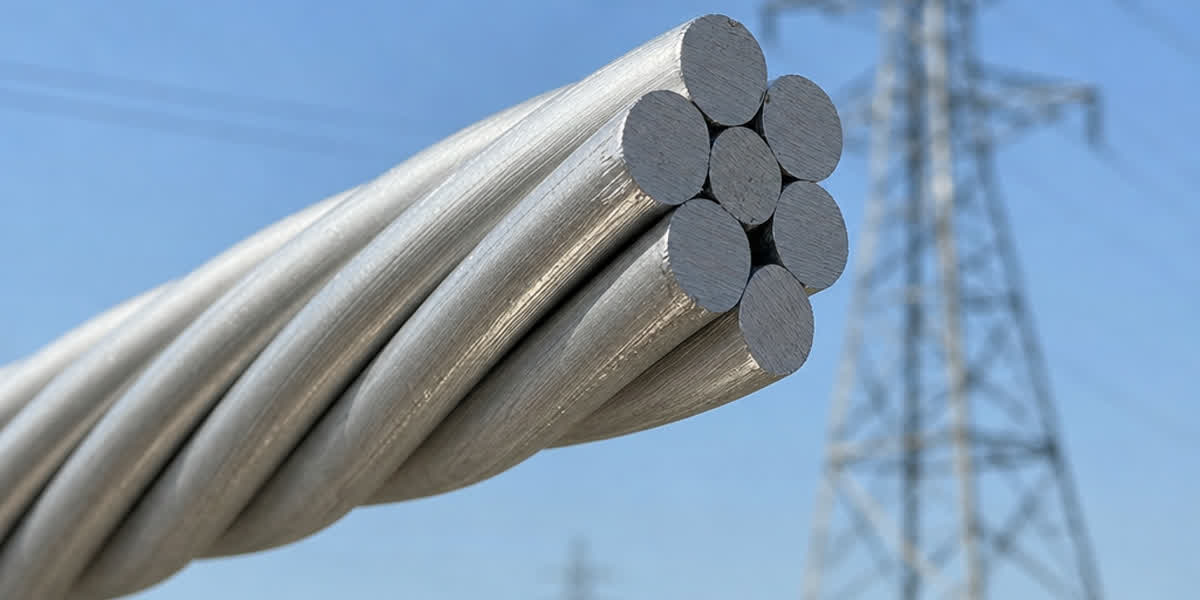
Optical Power Ground Wire (OPGW) is a dual-function cable that serves as both a lightning-protection overhead ground wire and a high-bandwidth optical fiber communication channel on transmission lines. Proper installation and maintenance of OPGW are critical — the cable operates in the harshest environment atop transmission towers, exposed to lightning strikes, ice loading, wind-induced vibration, and electrical stress.
A poorly installed OPGW can fail catastrophically, taking down both the grounding system and the communication link simultaneously. This guide is written for field engineers, project managers, linemen, and utility maintenance crews who need practical, standards-based installation procedures and long-term maintenance strategies for OPGW on lines from 33 kV to 765 kV.
Scope: This guide covers pre-installation planning, hardware selection, stringing procedures, splicing, post-installation testing, routine maintenance, and troubleshooting. It references IEEE 1138, IEC 60794-4-10, CIGRE TB 308, and national utility standards.
2. Pre-Installation Preparation
2.1 Receiving and Storage
| Inspection Item | Acceptance Criteria |
|---|---|
| Drum damage | No broken flanges, no crushed drum heads |
| Cable end seal | Intact, no moisture ingress |
| Fiber continuity | OTDR trace confirms all fibers intact (≤0.05 dB/km splice loss target) |
| Coating condition | No cracks, no exposure to UV for >6 months |
| Documentation | Supplier test certificate, fiber map, splice loss budget |
⚠️ Storage: Store OPGW drums on firm, level ground. Drums must be covered (UV degrades the loose tube sheathing over months). Never store drums on their sides — the cable can shift and kink. Maximum outdoor storage: 6 months without intermediate testing.
2.2 Tools and Equipment Checklist
| Tool Category | Required Items | Application |
|---|---|---|
| Pulling | Swivel pulling grip (5-ton min.), pulling line (dyneema/steel), tensioner, bullwheel tensioner | OPGW pulling without rotating the cable |
| Splicing | Fusion splicer (single-mode, ≤0.02 dB loss), cleaver, LID system, splice protection sleeves | Fiber splicing at tower & joint locations |
| Testing | OTDR (min. 1310/1550 nm), power meter, light source, VFL (visible fault locator) | Pre- and post-installation fiber verification |
| Grounding | Grounding clamps (C-type, bolted), downlead clamps, surge arresters | Tower grounding continuity |
| Safety | GFCIs, rubber gloves (for induced voltage), fall arrest systems, warning signs | Personnel safety near energized lines |
2.3 Installation Plan Checklist
Before mobilizing to the tower site, confirm: - [ ] Pulling section lengths calculated (typically 2–4 km per section; 3–6 km maximum for heavy structures) - [ ] Tensioner and pulling equipment positioned correctly for de-rotation pulling - [ ] Tower hardware (suspension clamps, tension sets, downlead clamps) pre-installed - [ ] Splicing locations identified (intermediate joint towers or dedicated fiber huts) - [ ] Fiber count verified against design documents - [ ] Weather forecast acceptable (no lightning within 10 km, wind < 40 km/h)
3. Engineering Calculations
3.1 Design Parameters
| Parameter | Typical Value | Notes |
|---|---|---|
| Design tension (EDS) | 15%–25% of RTS | Higher for ice regions, lower for vibration-prone spans |
| Maximum installation tension | 33% of RTS (IEC 60826) | At +15°C, no ice, no wind |
| Temperature range | −40°C to +80°C (conductor), −20°C to +60°C (fiber) | Fiber window: −10°C to +60°C for ≤0.1 dB/km added loss |
| Fiber strain limit | 0.25%–0.5% (stranded loose tube) | Beyond this: permanent fiber damage |
| Ruling span | 300–500 m (typical 66–220 kV lines) | Use actual span length distribution for stringing charts |
3.2 Sag-Tension Computation
For OPGW, the sag-tension relationship follows the same catenary equations as conventional overhead ground wires, but with two critical differences:
- Fiber strain limit — The stringing tension must never exceed the value that produces 0.25% fiber strain in the loose tubes. This is typically 20–30% of RTS.
- Creep — OPGW has negligible creep compared to ACSR (the steel/aluminum stranding is thermally stable). However, the fiber loose tubes can compress under sustained high tension, altering the fiber path and increasing attenuation.
💡 Rule of thumb: For most 48-fiber OPGW designs, stringing tension of 15–20% RTS gives optimal sag and fiber strain margin. In ice regions, use 20–25% RTS to prevent galloping.
3.3 Vibration Analysis
| Vibration Type | Frequency Range | OPGW Risk | Mitigation |
|---|---|---|---|
| Aeolian vibration | 3–150 Hz | Fatigue at suspension clamps | Spiral vibration dampers (AVDs) or rubber-lined clamps |
| Galloping | 0.15–1 Hz | Ice-induced, high amplitude | Interphase spacers, twisting-resistant OPGW |
| Wake-induced oscillation | 0.15–2 Hz | Bundle conductors only | Not applicable (OPGW is single) |
Standard practice: Install spiral dampers within 1 m of each suspension clamp for spans exceeding 300 m, or for any span in wind-prone areas (avg. wind > 5 m/s).
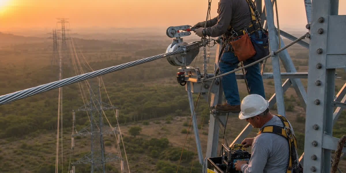
4. Installation Procedure
4.1 Setup and Preparation
- Position the tensioner at one end of the pulling section. The OPGW drum must feed into the tensioner from the top with a back-tension of 1–2% RTS.
- Run the pulling line through all traveler blocks (pre-installed on tower arms). Traveler block pulley diameter: ≥ 20× OPGW diameter (minimum 500 mm).
- Attach the swivel pulling grip to the OPGW end. Ensure it rotates freely — this is critical to prevent fiber strain from twist accumulation.
- Ground the pulling line at both ends before attaching to the OPGW.
⚠️ Safety: Induced voltages on de-energized lines can exceed 15 kV from adjacent energized circuits. Bond and ground all pulling equipment at both ends before handling.
4.2 Stringing Procedure
| Step | Action | Requirements |
|---|---|---|
| 1 | Start pulling at constant speed (0.3–0.5 m/s) | Do NOT exceed 33% RTS on the tensioner setting |
| 2 | Monitor tension continuously | Data-logger recommended |
| 3 | Maintain sag target using stringing chart | ±2.5% sag tolerance |
| 4 | Stop pulling when first dead-end is reached | Leave 3–5 m tail at each end for splicing |
| 5 | Clip-in permanent suspension clamps | Ensure clamp liner matches OPGW diameter (±0.5 mm) |
| 6 | Install armor rods or spiral dampers | Within 24 hours of stringing |
De-rotation pulling: OPGW must be pulled with a non-rotating pulling grip (swivel feature) because any rotation accumulates twist that can strain the fiber core. Never use a rotating pulling grip or choker-type grip on OPGW.
4.3 Hardware Installation
| Component | Application | Standards |
|---|---|---|
| Suspension clamp | Tangent towers (0°–3° line angle) | IEEE 1138, IEC 61284 |
| Tension/Dead-end set | Angle towers (≥3°), terminal towers | IEEE 1138, IEC 61284 |
| Downlead clamp | Tower body fiber transition | IEEE 1138, IEC 61772 |
| Joint box (splice box) | Fiber splicing location | IEC 60794-4-20, IP66 |
4.4 Splicing Procedure
- Secure both OPGW tails in the tower splice box (or on the ground for hut splicing). Leave minimum 15 m of fiber tail coiled in the splice box.
- Strip the OPGW — remove the outer layer(s) of stranded wires carefully using hydraulic cutters. Do NOT use angle grinders — heat damages the fiber tubes.
- Identify fibers — use the supplier's color-code map. Typical 48-fiber OPGW uses 4 loose tubes × 12 fibers each (standard color: blue, orange, green, brown, slate, white).
- Cleave and splice each fiber using a fusion splicer. Target loss: ≤0.02 dB per splice.
- Heat-shrink protection sleeves over each splice.
- Coil splices in the splice tray — minimum bend radius 30 mm.
- Test with OTDR in both directions. Record bi-directional average loss.
💡 Tip: A good field splice results in OTDR loss < 0.05 dB. If you see > 0.1 dB or a reflective event (> 0.5 dB reflectance), re-splice.
5. Post-Installation Testing
| Test | Method | Acceptance Criteria |
|---|---|---|
| Fiber end-to-end attenuation | OTDR, 1310 nm and 1550 nm | ≤0.35 dB/km (1310 nm), ≤0.25 dB/km (1550 nm) |
| Splice loss verification | Bi-directional OTDR | Average ≤0.05 dB per splice, maximum ≤0.10 dB |
| Reflectance | OTDR event reflectance | ≤ −65 dB (single-mode) |
| Grounding continuity | Micro-ohmmeter (DC resistance) | ≤10 mΩ between tower and OPGW clamp |
| Visual inspection | Drone or binoculars from ground | No kinks, no abrasion, no loose armor rods |
⚠️ If any single fiber exceeds 0.4 dB/km at 1550 nm, check for macro-bends in splice trays or fiber pinching in the joint box.
6. Routine Maintenance Schedule
| Frequency | Maintenance Activity |
|---|---|
| Monthly | Visual inspection via drone/patrol: check for broken strands, loose clamps, foreign objects |
| Quarterly | Thermal imaging of tension clamps and splice boxes (hot spots indicate loose connections or corrosion) |
| Semi-annual | OTDR trend testing: compare fiber attenuation against baseline. Any increase > 0.05 dB/km requires investigation |
| Annual | Sag measurement at three reference spans. Compare against as-built. > 5% change indicates creep or ice damage |
| Every 5 years | Full hardware inspection: replace ground clamps showing corrosion > 20% section loss |
| Every 10 years | Random destructive testing of 1 drum-length OPGW from inventory block: full mechanical + optical test |
Thermal Imaging Protocol
- Equipment: IR camera with ≥ 320 × 240 resolution, temperature sensitivity ≤ 0.05°C
- Inspection window: Clear weather, wind < 3 m/s, ambient 0°C–40°C
- Targets: All tension clamps, downlead bonding connections, splice box fittings
- Acceptance criteria: ∆T < 10°C above ambient for clamps; ∆T < 5°C for splice box
7. Troubleshooting Common Issues
| Problem | Likely Cause | Solution |
|---|---|---|
| High fiber attenuation (>0.4 dB/km) in one tube | Macro-bend at splice tray or pinched fiber in joint box | Open splice box, re-inspect fiber routing, re-coil loose fiber with ≥30 mm bend radius |
| Transient fiber loss during temperature change | Fiber strain near loose tube limit; outdoor temp extreme | If permanent: re-string with lower tension (reducing to 15% RTS gains 0.1% headroom) |
| Broken strand(s) at suspension clamp | Aeolian vibration fatigue, no dampers installed | Install spiral vibration dampers; clamp repair or OPGW replacement if >3 adjacent strands broken |
| High splice loss (>0.1 dB) | Dirty cleaver, poor arc calibration, incompatible fiber type | Re-cleave and re-splice with cleaned equipment |
| Ground continuity >10 mΩ | Corroded downlead clamp or loose bolted connection | Clean contact surfaces, re-torque to manufacturer spec, apply dielectric grease |
| Corrosion at coastal tower attachment | Chloride attack on aluminum-clad or stainless fittings | Replace with marine-grade fittings (316 SS), apply anti-corrosion wrap |
| OTDR event with high reflectance (>−50 dB) | Cracked fiber in splice; mechanical splice instead of fusion | Re-splice with fusion; verify cleave quality |
| Fiber break in mid-span | Lightning strike, gunshot, or ice shedding impact | Locate with OTDR; install repair splice mid-span (temporary), plan OPGW section replacement |
8. Safety Considerations
| Hazard | Precaution |
|---|---|
| Induced voltage on de-energized OPGW | Bond and ground all pulling equipment at both ends. Use rated grounding switches. Treat as energized. |
| Falling from height during tower work | 100% tie-off with double lanyard on towers >10 m. Wind < 40 km/h for tower-top work. |
| Eye damage from fusion splicer arc | Never look directly at the arc. Use auto-darkening filter or LCD screen. |
| Laser hazard from OTDR/VFL | Class 1M/3R: do not look into the fiber end. Cap unused connectors. |
| Oil/chemical spills from hydraulic pulling equipment | Secondary containment under tensioner. Clean immediately. |
| Lightning proximity | Cease tower work if lightning within 10 km. Wait 30 minutes after last strike. |
9. FAQ
Q1: What is the maximum pulling length for OPGW? Standard pulling sections are 2–4 km for 48-fiber OPGW on 220 kV towers. Maximum pulling length is 6 km with intermediate tensioner repositioning. Beyond this, friction in travelers increases pulling tension above the safe limit.
Q2: Can OPGW be installed on an energized transmission line? No — OPGW installation requires the line to be de-energized and grounded. The induced voltage from adjacent energized circuits can still exceed 15 kV. Live-line OPGW installation (using hot-line tools) is possible in some jurisdictions but requires special training and equipment.
Q3: How do I detect OPGW fiber degradation before failure? OTDR trend testing (quarterly) is the gold standard. A gradual increase in attenuation of 0.01–0.02 dB/km per quarter suggests developing hydrogen darkening or micro-bending. Perform a polarization-mode dispersion (PMD) test annually if the link carries 10 Gbps or higher.
Q4: What is the typical lifespan of an OPGW installation? 30–40 years with proper maintenance. The optical fiber itself has a theoretical lifespan exceeding 50 years. Failure modes typically involve corrosion of the metallic outer layer, aeolian vibration fatigue, or lightning damage.
Q5: How often should OPGW splices be inspected after commissioning? Splice boxes should be inspected visually during quarterly maintenance (check seal integrity, moisture ingress). The splices themselves are passive and do not require re-inspection unless OTDR shows new high-loss events at the splice location.
Q6: Can different OPGW types be spliced together? Yes, if both have the same fiber type (G.652D or G.655), similar mode field diameter, and the same number of fibers per tube. However, mixing stranding types (central loose tube vs. stranded loose tube) complicates splice box accommodation. ALWAYS verify the splice loss budget with a bi-directional OTDR after any mixed-type splice.
Q7: What is the minimum bending radius for OPGW during installation? During installation: 20× the OPGW diameter. During operation (static): 15× the OPGW diameter. In splice trays: ≥ 30 mm for individual coated fibers (or as specified by the cable manufacturer).
Q8: Does snow or ice affect OPGW optical performance? Ice loading increases tensile stress on the OPGW, which can strain the fibers. For well-designed OPGW (fiber strain margin ≥ 0.25%), an ice load of 50 mm radial thickness at −5°C will increase fiber attenuation by less than 0.05 dB/km. Beyond 80 mm ice, fiber strain can exceed the 0.5% emergency limit, risking permanent damage.
10. References and Standards
| Standard | Description |
|---|---|
| IEEE 1138 | Standard for testing of OPGW for use on electric utility power lines |
| IEC 60794-4-10 | Optical fibre cables — Part 4-10: Sectional specification for OPGW |
| IEC 60794-4-20 | Optical fibre cables — Sectional specification for aerial optical cables along electrical power lines |
| IEC 60826 | Design criteria of overhead transmission lines |
| IEC 61284 | Overhead lines — Requirements and tests for fittings |
| CIGRE TB 308 | OPGW installation and maintenance guide |
| CIGRE TB 425 | OPGW life cycle management and condition assessment |
| IEC 61772 | Optical ground wires — Downlead cable and accessories |
| IEC 61395 | Overhead electrical conductors — Creep test procedures |
| IEC 60652 | Loading tests on overhead line structures |
| CISPR 18-2 | Radio interference characteristics of overhead power lines |
| ISO/IEC 11801 | Generic cabling for customer premises (splice loss & reflectance limits) |
11. About SiTong Cable
SiTong Cable has manufactured and supplied OPGW for utilities and renewable energy projects across 50+ countries since 2010. Our OPGW products comply with IEEE 1138, IEC 60794-4-10, and national utility standards. We provide full technical documentation, splice loss budgets, stringing charts, and on-site training for installation crews.
👉 Browse our OPGW product range 👉 Contact our engineering team for installation support 👉 Read more: OPGW Complete Technical Guide
This guide was prepared by the SiTong Cable engineering team. All technical data references IEEE 1138, IEC 60794-4-10, and CIGRE TB 308. For specific project requirements, contact sales@sitongcable.com or call +86-371-69176007.