STACIR/AW (HTLS) Installation & Maintenance: Complete Field Guide for High-Temperature Low-Sag Overhead Lines
STACIR/AW (HTLS) Installation & Maintenance: Complete Field Guide for High-Temperature Low-Sag Overhead Lines
Complete field guide to installing and maintaining STACIR/AW (HTLS) conductors — invar-core sag control, tension stringing, compression fittings, thermal inspection and troubleshooting.
1. Introduction
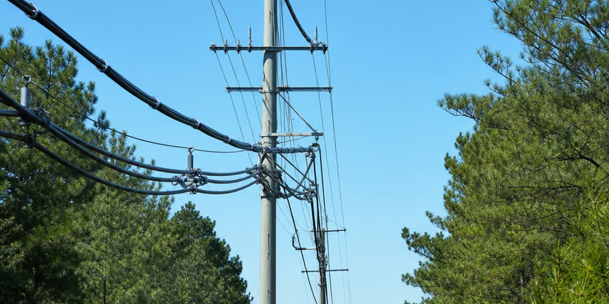
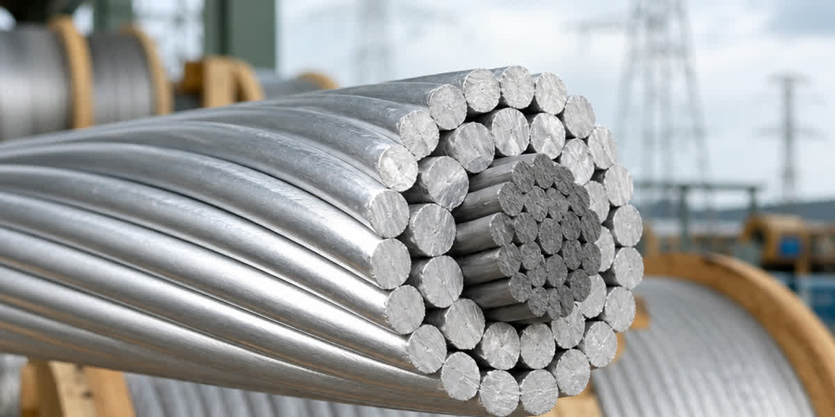
High-Temperature Low-Sag (HTLS) conductors are the workhorse of transmission line uprating projects, and STACIR/AW (Super Thermal-resistant Aluminum Conductor Invar Reinforced) is one of the most field-proven variants in service today. Unlike conventional ACSR conductor, which is thermally limited to roughly 90–100°C continuous operation, STACIR/AW is designed to operate at 150°C continuous and up to 210°C in emergency conditions — while its invar (iron-nickel, ~36% Ni) core, with a coefficient of thermal expansion (CTE) of roughly 3 × 10⁻⁶/°C, keeps sag growth a fraction of what a steel core would produce. The result: 50–100% ampacity gains on existing tower geometry without rebuilding structures.
However, these performance advantages only materialize if the conductor is handled, strung, spliced and maintained correctly. STACIR/AW is not an ACSR conductor that runs hot — its invar core, zirconium-doped thermal-resistant aluminum (ZTAL) strands, and elevated operating temperatures change every step of the installation and maintenance workflow: stringing tensions must respect the composite core/strand load share, compression dies must be sized for the invar core, and thermal inspection becomes a scheduled activity rather than an occasional check.
This guide is written for transmission line engineers, field supervisors, linemen, and utility maintenance crews. It covers pre-installation preparation, sag-tension engineering, the full stringing procedure, post-installation testing, a routine maintenance schedule, troubleshooting, and safety. For selection criteria, specification tables, and international standards comparison, see our companion guide HTLS Conductor (STACIR/AW): Complete Technical Guide.
2. Pre-Installation Preparation
2.1 Receiving and Storage
| Check | Acceptance Criteria |
|---|---|
| Drum condition | No broken lagging; flanges intact; no signs of impact damage |
| Drum rotation | Arrows visible; conductor pays off over the top (cable off the top of drum) |
| End seal | Both ends sealed against moisture ingress |
| Sample test | Take 3 m sample per drum; verify stranding and lay direction against ASTM B941 |
| Storage | Horizontal on cribbing ≥150 mm off ground; cover with breathable tarp; never stack more than 3 drums high |
| Temperature | Store away from heat sources — ZTAL strands retain strength only if not annealed in storage |
Critical: STACIR/AW drums must not be stored in direct contact with the ground or in standing water. The aluminum-clad invar core is corrosion-resistant, but prolonged moisture contact with unclad end terminations can initiate galvanic activity. If a drum has been stored for more than 6 months, rotate it 90° every 3 months to prevent core settlement.
2.2 Tools and Equipment Checklist
| Tool Category | Items | Application Notes |
|---|---|---|
| Pulling | Pulling grips (Kellems-style or compression pulling eyes), swivels, stringing blocks (travelers) | Traveler groove diameter must be ≥20× conductor diameter; use 762 mm (30 in) minimum for 400 mm² and above |
| Tensioning | Tensioner with bullwheel, reel stands, brake | Bullwheel groove must be lined with neoprene or polyurethane; no steel-to-aluminum contact |
| Splicing | Full-tension compression dies, hydraulic pump (≥100 MPa), cutters | Dies per connector manufacturer's data sheet — invar core dies differ from ACSR steel dies |
| Sagging | Transit/theodolite, sag boards, temperature probe, dynamometer | Sag at 150°C design temperature requires careful ambient correction |
| Vibration | Stockbridge dampers, spacer dampers, armor rods | Per design — mandatory for spans >200 m or where Aeolian vibration risk exists |
| Grounding | Grounding clamps, bonding cables, personal protective grounds | Induced voltage on adjacent live circuits can exceed 100 V — always ground the work section |
| Measurement | Optical pyrometer or IR camera, resistance meter (micro-ohmmeter) | For post-installation joint verification and thermal imaging |
2.3 Installation Plan
Before mobilization, the contractor shall prepare a stringing plan covering: pulling section lengths (typically 3–6 km between set-up locations), traveler placement and sagging points, crossing protection (roads, railways, LV/MV lines), and the sequence of tension stringing per IEEE 524. For reconductoring jobs on live corridors, confirm outage windows and coordinate with the control center — induced voltage mitigation is part of the plan, not an afterthought.
⚠️ Warning: Never pull STACIR/AW with a steel pulling line directly on the conductor. Always use a swivel between the pulling line and the pulling grip, and maintain the pulling tension below 20% of the rated tensile strength (RTS) during stringing, or the manufacturer's recommended maximum, whichever is lower.
3. Engineering Calculations
3.1 Design Parameters
| Parameter | STACIR/AW Typical Value | Notes |
|---|---|---|
| Max continuous operating temp | 150°C | ZTAL strands retain strength at 150°C |
| Max emergency operating temp | 210°C | Short-term (≤2 h cumulative per event) |
| Core CTE | ~3 × 10⁻⁶/°C | Invar Fe-36Ni |
| Strand CTE | ~23 × 10⁻⁶/°C | ZTAL aluminum alloy |
| Initial modulus | ~70–80 GPa composite | Depends on strand/core area ratio |
| Creep | Low at 150°C | ZTAL alloy designed for elevated-temp creep resistance |
3.2 Sag-Tension Computation (Knee-Point Behavior)
STACIR/AW exhibits knee-point behavior similar to ACSS: below the knee-point temperature (typically 80–120°C depending on the strand/core area ratio), both the aluminum strands and the invar core share the tension; above the knee point, the aluminum strands have expanded and relaxed, and the invar core carries nearly all the mechanical load. This is what keeps sag flat at high temperature.
Use the composite-model method per CIGRE TB 324 (Sag-Tension Calculation Methods for Overhead Lines), never the simple parabolic approximation used for ACSR:
Sag = (w × L²) / (8 × H)
where w = unit weight (N/m), L = ruling span (m), H = horizontal tension (N). The tension H must be solved iteratively for the two-material composite, accounting for:
- Initial (unloaded, 15°C) stringing condition
- Final condition after creep (see §3.3)
- 150°C continuous operating condition
- 210°C emergency condition
- Ice + wind loading per IEC 60826 or local loading zones
Verification rule: The sag at 150°C shall not exceed the design clearance limit, and the tension at −5°C with ice load shall not exceed 40% RTS (or the value specified by the project).
3.3 Creep Compensation
Aluminum-alloy strands creep over time, and at elevated temperatures creep accelerates. Per CIGRE TB 244, HTLS installations should account for:
| Creep Type | Cause | Magnitude (typical) | Mitigation |
|---|---|---|---|
| Initial creep | Strand settlement and inter-layer compaction | 0.1–0.3% strain in first 6 months | Pre-stress or sag correction at stringing |
| Thermal creep | Long-term exposure at 150°C | 0.05–0.15% over 20 years | Use manufacturer creep curves; design final sag accordingly |
| Core creep | Negligible for invar | <0.02% | Invar does not creep appreciably at ≤210°C |
Practical approach: Install at the stringing temperature with sag set for the final (creeped) condition, or apply an initial over-tension for 1–2 hours ("pre-stressing") to accelerate initial creep out of the span. Confirm the approach with the conductor manufacturer before stringing.
4. Installation Procedure
4.1 Setup and Stringing
- Position equipment: Place the tensioner at the pulling end and the bullwheel tensioner at the set-up location, aligned with the line direction.
- Install travelers: Hang stringing blocks at each structure; check that traveler saddles are free to rotate and are sized for the conductor diameter (groove ≥20× diameter).
- Thread pilot line: Pull a synthetic pilot line (never steel) through the travelers.
- Attach pulling grip: Connect the pilot line to the pulling grip via a swivel. For 400 mm² and above, use a compression pulling eye that will later be cut off — do not pull on a temporary grip at high tension.
- String the conductor: Maintain tension such that the conductor never touches the ground, trees, or structures. Maximum stringing tension: 20% RTS (or 25% with prior approval), and never exceed the traveler-rated load.
- Sag the span: Using the sagging method (transit + sag boards or dynamometer), set sag to the stringing chart value corrected for the actual ambient temperature at the time of sagging. Do not sag by "feel" — at 150°C design, a 10°C sagging error changes clearance significantly.
- Clip-in: Transfer the conductor from travelers into suspension clamps or armor rod assemblies at each structure. Ensure the clamp cushions (neoprene or similar) are installed — bare metal-to-aluminum contact is prohibited.
- Dead-end: Install full-tension dead-ends per the manufacturer's instructions. STACIR/AW dead-ends use compression fittings with the invar core inserted into the core barrel.
4.2 Splicing and Compression
Splicing is the highest-risk activity for HTLS conductors — a poor splice becomes a hot spot at 150°C.
| Step | Requirement |
|---|---|
| Connector selection | Use connectors rated for 210°C continuous, tested per IEC 61238-1 / IEEE 575 |
| Core preparation | Strip aluminum strands carefully; do not nick the invar core wires |
| Die selection | Use dies specified for the STACIR/AW core/strand combination — do NOT reuse ACSR dies (invar core is harder than galvanized steel and requires different compression) |
| Compression | Full-tension splice: compress core barrel first, then aluminum sleeve from center outward; hydraulic pressure ≥100 MPa per connector data sheet |
| Verification | After compression, measure resistance across the joint with a micro-ohmmeter — shall be ≤1.1× equivalent conductor length resistance; mark and record joint locations |
| Repair splices | Tension-repair splices only per manufacturer approval; never use bolted/parallel-groove clamps for full-tension repairs on spans |
💡 Tip: For 400 mm² and above STACIR/AW, use two-piece (core + aluminum) compression splices. One-piece splices are acceptable only below 240 mm² and only with manufacturer approval. Document every splice with GPS coordinates — this is essential for the thermal inspection program in §6.
4.3 Vibration Mitigation
Aeolian vibration is the primary fatigue risk on HTLS lines, and the elevated operating temperature does not reduce it. Install per design:
| Countermeasure | Application | Standard |
|---|---|---|
| Stockbridge dampers | Spans >200 m; 1–2 per span end | IEEE 664 |
| Spacer dampers | Bundle conductors (2 or 4 subconductors) | IEEE 524 |
| Armor rods | Suspension points and where clamps contact conductor | IEC 61284 |
| Vibration recorders | Long spans, river crossings, open terrain | — |
Install dampers within 0.5–1.5 m of the suspension clamp per the damper manufacturer's placement chart. Retighten damper clamps at the first annual inspection.
5. Post-Installation Inspection & Testing
| Inspection Item | Acceptance Criteria | Method |
|---|---|---|
| Sag verification | Measured sag within ±2% of design value at ambient temperature | Transit survey or laser rangefinder |
| Splice resistance | ≤1.1× equivalent length resistance | Micro-ohmmeter across each joint |
| Corona / radio interference | No audible/visible corona at rated voltage; RI within CISPR 18-2 limits | Night inspection + RI meter |
| Grounding continuity | <1 Ω between structures and ground | Clamp-on ground tester |
| Hardware torque | All bolts at specified torque; cotter pins installed | Torque wrench |
| Conductor surface | No nicks, abrasions, or crushed strands from travelers/clamps | Visual + drone inspection |
First energization: After energizing, perform a thermal imaging survey within 24 hours at load. Document the thermal profile as the baseline for the maintenance program.
6. Routine Maintenance Schedule
| Frequency | Maintenance Activity |
|---|---|
| Monthly (first 3 months) | Visual check of new splices and dead-ends for signs of overheating |
| Semi-annual | Thermal imaging of all splices, dead-ends, and jumpers — compare against baseline; any joint >10°C above the adjacent conductor temperature shall be flagged |
| Annual | Sag measurement and trend analysis; damper inspection and retorque; hardware check; vegetation clearance audit |
| Every 2 years | Corona/RI survey; insulator and hardware visual inspection (drone or climbing) |
| Every 5 years | Full line inspection: conductor surface, corrosion check at coastal sections, sample splice resistance testing |
| Every 10 years | In-depth audit: re-verify sag-tension against design, review thermal history (conductor temperature monitors if installed), replacement planning |
⚠️ Thermal imaging threshold: On HTLS lines, a splice running 10°C above the adjacent conductor at 150°C load is a developing fault — schedule repair within 30 days. At 20°C above, take the line out of service or transfer load immediately.
7. Troubleshooting Common Issues
| Problem | Likely Cause | Solution |
|---|---|---|
| Hot splice detected in thermal survey | Under-compressed core barrel; wrong dies; loose jumper | De-rate line, re-compress or replace splice per manufacturer procedure |
| Sag greater than design at high load | Creep not compensated at stringing; wrong sagging temperature | Re-verify with sag-tension software; plan re-sag if clearance violated |
| Conductor vibration / fatigue marks near clamps | Missing or misplaced dampers; armor rods absent | Install dampers per placement chart; inspect strands for fatigue cracks |
| Corrosion at coastal section | Unclad core exposure at splice; damaged cladding | Replace affected section; apply corrosion inhibitor at joints |
| RI / audible noise at night | Surface contamination, water droplets, or damaged strands | Clean or repair; check for corona rings at terminations |
| Pulling grip slip during stringing | Wrong grip size; tension too high | Stop stringing, re-rig with correct grip; inspect conductor for damage |
| Strand birdcaging at splice | Improper cut-back; die mismatch | Re-splice with correct die set; cut back damaged strands |
8. Safety Considerations
| Hazard | Precaution |
|---|---|
| Induced voltage on de-energized line | Ground both ends of the work section; use personal protective grounds; bond stringing equipment |
| High pulling tension (up to 20% RTS) | Keep personnel clear of the pulling path; use proper barriers and tag lines |
| Elevated temperature exposure (150–210°C design) | Assume conductor may be hot during maintenance on loaded lines; use thermal imaging before touching |
| Falls during tower work | Full fall protection; work positioning per local regulations |
| Compression tooling (≥100 MPa hydraulic) | Operator training; never place hands between dies; use tool guards |
| Corona / electric field exposure | Maintain clearances at energized structures; use EMF-safe work practices |
9. FAQ
Q1: Can STACIR/AW be strung with the same tension as ACSR? No. STACIR/AW stringing tension is typically limited to 20% of RTS (versus 15–25% for ACSR depending on project), but the critical difference is the composite load share: because the invar core carries most of the load above the knee point, stringing tension must be verified against the composite sag-tension model per CIGRE TB 324, not the ACSR parabolic approximation.
Q2: What is the knee-point temperature of STACIR/AW? The knee point is the temperature at which the aluminum strands have expanded enough to shed their tension to the core — typically 80–120°C for STACIR/AW depending on the strand/core area ratio. Above the knee point, sag growth is governed almost entirely by the invar core's ~3 × 10⁻⁶/°C CTE, which is why sag stays flat up to 210°C.
Q3: Are standard ACSR compression dies acceptable for STACIR/AW splices? No. The invar core has different hardness and diameter characteristics than galvanized steel core wire. Always use the connector manufacturer's die set and compression schedule for the specific STACIR/AW size. Using ACSR dies is a common cause of under-compressed, high-resistance joints that overheat at 150°C.
Q4: How often should thermal imaging be performed on an HTLS line? At minimum semi-annually, and within 24 hours of first energization to establish the baseline. Monthly checks are recommended for the first 3 months after installation. Any splice more than 10°C above adjacent conductor temperature requires action within 30 days; 20°C requires immediate load reduction.
Q5: Does STACIR/AW require special hardware for 210°C operation? Yes. All fittings — dead-ends, splices, suspension clamps, armor rods, jumpers — must be rated for continuous operation at 210°C. Standard ACSR hardware rated for 90–100°C will lose mechanical properties and corrode at HTLS operating temperatures. Specify HTLS-rated hardware at procurement.
Q6: Can existing ACSR towers be reused when reconductoring with STACIR/AW? In most cases yes — that is the core value proposition of HTLS reconductoring. However, the tower loads must be re-verified: STACIR/AW is typically heavier than the ACSR it replaces, and the higher tension at low temperature (if any) must be within tower and foundation limits. A full structural assessment per IEC 60826 is required.
Q7: What is the maximum span length for STACIR/AW? There is no fixed maximum, but spans over 400 m require manufacturer-specific sag-tension data at 150°C and 210°C, plus a vibration study. STACIR/AW has been used on river crossings and long-span applications; consult the manufacturer for spans above 600 m.
Q8: How do you detect corrosion on an aluminum-clad invar core? The aluminum cladding protects the invar core galvanically, but corrosion can initiate where the cladding is damaged (at splices, clamp points, or handling damage). Annual visual inspection plus targeted resistance checks at coastal or industrial sections will reveal developing issues — a 20% resistance increase in a joint is a strong indicator of developing corrosion.
10. References and Standards
| Standard | Description |
|---|---|
| ASTM B941 | Concentric-Lay-Stranded Aluminum Conductors, Aluminum-Clad Invar (STACIR/AW) — primary construction standard |
| IEEE 524 | Guide to the Installation of Overhead Transmission Line Conductors |
| IEEE 738 | Standard for Calculating the Current-Temperature Relationship of Bare Overhead Conductors |
| IEEE 664 | Guide for Laboratory Measurement of the Power Dissipation Characteristics of Aeolian Vibration Dampers |
| IEC 61089 | Round Wire Concentric Lay Overhead Electrical Stranded Conductors |
| IEC 60826 | Design Criteria of Overhead Transmission Lines |
| IEC 61284 | Overhead Lines — Requirements and Tests for Fittings |
| IEC 61238-1 | Compression and Mechanical Connectors for Power Cables — Part 1 |
| IEC 61597 | Overhead Electrical Conductors — Calculation Methods for Stranded Bare Conductors |
| CIGRE TB 244 | Conductors for the Uprating of Overhead Lines |
| CIGRE TB 324 | Sag-Tension Calculation Methods for Overhead Lines |
| CISPR 18-2 | Radio Interference Characteristics of Overhead Power Lines — Methods of Measurement |
11. About Sitong Cable
Sitong Cable is a professional manufacturer of overhead conductors, including ACSR conductor, AAAC conductor, AAC conductor, and ACAR, produced to ASTM B941, IEC 61089 and BS 215 standards. Our engineering team supports sag-tension studies, stringing plans, and installation training for HTLS and conventional conductor projects worldwide.
👉 Browse our ACSR conductor range 👉 HTLS Conductor (STACIR/AW): Complete Technical Guide — Standards, Specifications & Selection 👉 Contact our team
📬 Sales inquiries: sales@sitongcable.com | 📞 Phone: +86-371-69176007
This guide was prepared by the Sitong Cable engineering team. All technical data references ASTM B941, IEEE 524, IEEE 738, IEC 61089, IEC 60826, CIGRE TB 244 and CIGRE TB 324.