ACAR Conductor Installation & Maintenance: Complete Field Guide
ACAR Conductor Installation & Maintenance: Complete Field Guide
This guide provides a comprehensive technical reference for field engineers, linemen, and maintenance crews working with ACAR (Aluminum Conductor Alloy Reinforced) overhead conductors. Covering pre-installation preparation, stringing procedures, compression splicing, post-installation inspection, routine maintenance, troubleshooting, and safety — this field guide is designed to ensure reliable long-term performance of ACAR conductors in 69 kV to 345 kV transmission lines, river-crossing spans, and coastal or industrial environments.
💡 Audience: Field installation engineers, transmission line technicians, maintenance crews, and project managers.
1. Pre-Installation Preparation
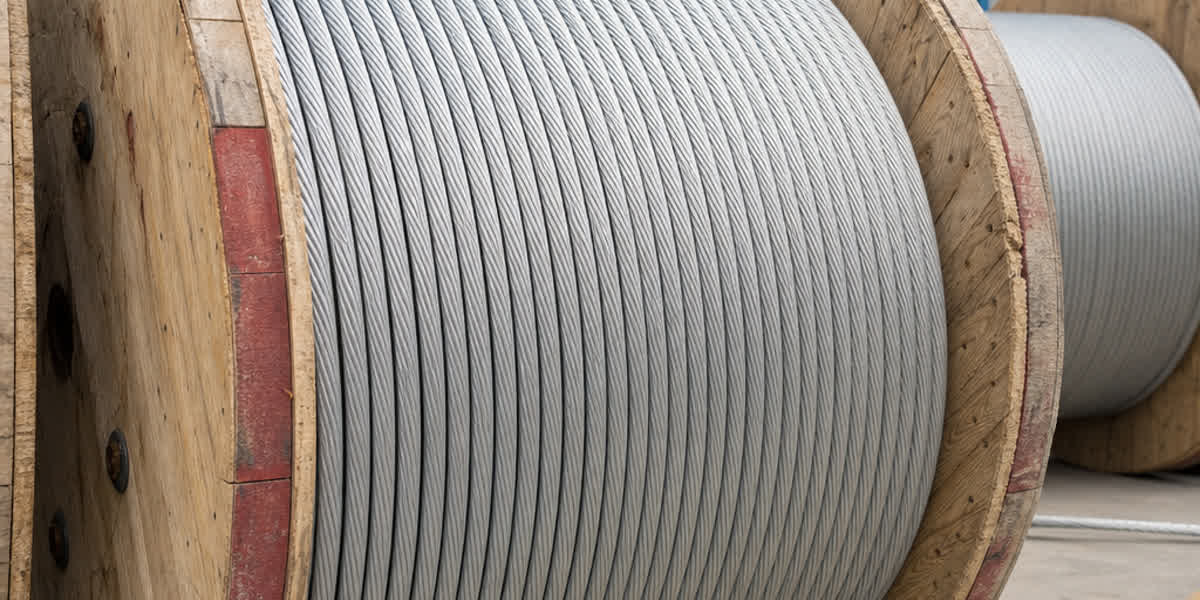
1.1 Receiving and Storage
| Inspection Item | Acceptance Criteria | Notes |
|---|---|---|
| Visual inspection | Reel undamaged, no signs of impact | Transport collisions may deform reels |
| Conductor surface | No scratches, corrosion spots, lay separation, or abrasion | Outer 1350-H19 aluminum strands are softer and more prone to mechanical damage |
| Label verification | Reel tag matches order (type, length, spec) | Confirm alloy-to-aluminum ratio (e.g., 15/4, 22/7) |
| End sealing | Ends properly sealed, no moisture ingress | Water ingress can corrode alloy strands |
| Storage conditions | Indoor or covered storage, off ground | Reels stored upright, never stacked flat |
| Storage duration | ≤12 months; re-inspect if exceeded | Quarterly inspection for outdoor storage |
⚡ Tools and Equipment Checklist
| Tool Category | Tool Name | Purpose |
|---|---|---|
| Pulling equipment | Tensioner, puller, winch | ACAR requires tension stringing method |
| Stringing sheaves | Nylon-lined sheaves (proper diameter) | Sheave diameter ≥25× conductor diameter (ASTM B524) |
| Splicing tools | Hydraulic compressor (≥150 ton), matched dies | Alloy-core compression requires higher pressure than pure aluminum |
| Measurement | Thermal camera, dynamometer, sag scope | Sag adjustment and acceptance testing |
| Safety gear | Grounding clamps, jumper cables, insulating gloves | Induced voltage protection |
| Vibration control | Armor rods, vibration dampers, spacers | Per vibration design specification |
1.2 Installation Plan
A detailed installation plan shall be prepared before ACAR conductor stringing, including: - Pulling section lengths (recommended 2–5 km, adjusted for terrain) - Tensioner and puller setup locations and anchoring scheme - Crossing protection measures (railways, highways, power lines) - Communication protocol (real-time contact between pulling and tensioning ends)
2. Engineering Calculations
2.1 Design Parameters
The following design parameters shall be confirmed prior to ACAR installation:
| Parameter | Value | Standard |
|---|---|---|
| Maximum working tension | 18%–25% of RTS | IEC 61089 / ASTM B524 |
| Average operating tension (EDS) | 12%–18% RTS (lower in vibration-sensitive areas) | IEEE 738 / CIGRE TB 324 |
| Temperature range | −20°C to +50°C (site-specific extremes) | Project climate data |
| Ice loading | 5 mm to 20 mm ice thickness | IEC 60826 |
| Wind loading | 100-year return period maximum wind | IEC 60826 |
| Creep compensation | 0.04%–0.07% of conductor length (typical for ACAR) | CIGRE TB 324 |
2.2 ACAR-Specific Sag-Tension Considerations
ACAR sag-tension calculations differ from ACSR in several important ways:
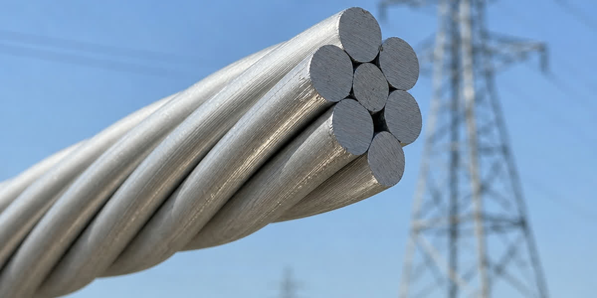
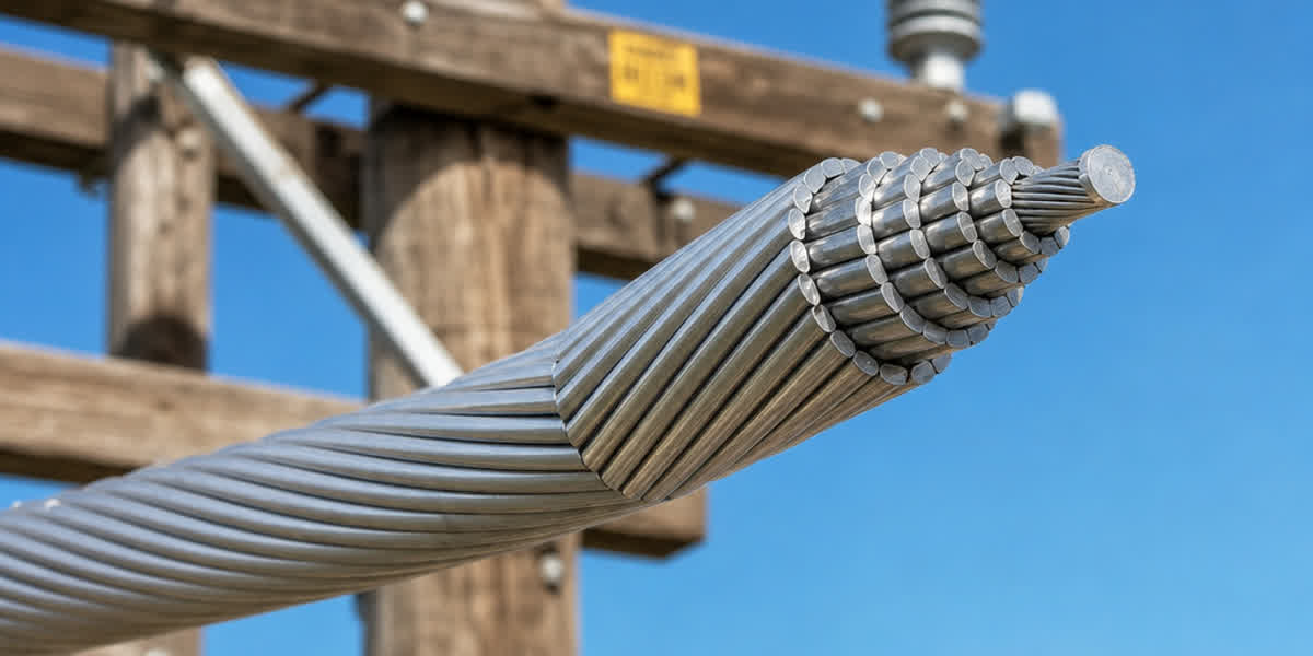
- Identical modulus and expansion: ACAR's 1350-H19 aluminum and 6201-T81 alloy strands share the same elastic modulus (69 GPa) and thermal expansion coefficient (23.0×10⁻⁶/°C). Unlike ACSR, there is no differential thermal stress between core and outer layers, simplifying sag-tension table preparation.
- Creep behavior: ACAR creep falls between AAC (high creep) and ACSR (low creep). Install with 0.03%–0.06% RTS creep elongation pre-compensation, depending on alloy-to-aluminum ratio. Higher alloy content (e.g., 37/8 configuration) results in creep closer to AAC levels.
- Temperature-sag relationship: ACAR sags 5%–10% more than equivalent-diameter ACSR at the same tension due to the absence of steel core support under high temperature. Use ACAR-specific sag-tension curves — never substitute ACSR data.
Key Formula (parabolic method):
D = (w × S²) / (8 × H × cos θ)
Where: - D = sag (m) - w = unit weight (N/m) - S = span length (m) - H = horizontal tension (N) - θ = angle of elevation difference
⚡ Quick Reference: For standard 300–500 m spans with ACAR 795 kcmil (22/7), the sag at 15°C and 20% RTS tension is approximately 7.8–13.5 m (exact values require site-specific sag-tension tables).
3. Installation Procedure
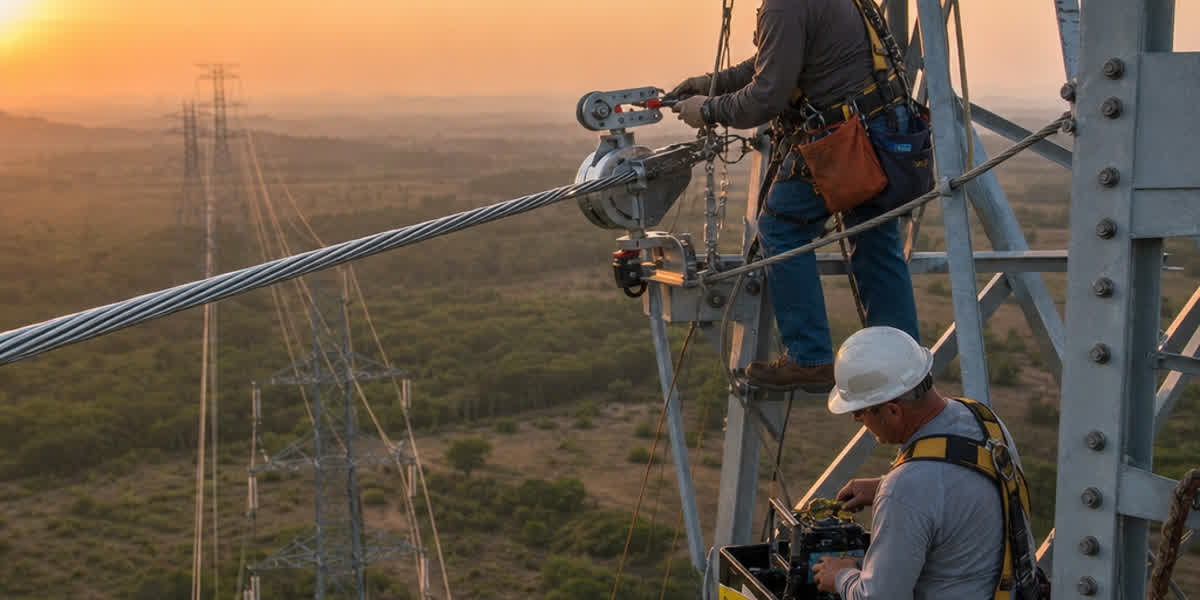
3.1 Tension Stringing
ACAR conductors must be installed using tension stringing (no-tension method). Drag stringing will severely abrade the outer 1350-H19 aluminum layer.
| Step | Operation | Requirements |
|---|---|---|
| 1 | Install stringing sheaves | Nylon-lined sheaves, diameter ≥25× conductor OD |
| 2 | Pilot line running | Use Dyneema or non-rotating braided rope |
| 3 | Swivel connection | Anti-rotation swivel to prevent conductor unwinding |
| 4 | Tension control | Pulling tension ≤15% RTS; conductor clearance ≥3 m from ground |
| 5 | Pulling speed | Rated speed ≤5 km/h; 2–3 km/h at critical crossings |
| 6 | Crossing protection | Install roller guards or crossing frames at obstacles |
⚠️ Safety Warning: Induced voltage is the primary electrical hazard. Both ends of the pulling section must be reliably grounded. The tensioner and puller shall have independent ground connections. Do not touch the conductor during stringing.
3.2 Sagging
| Step | Operation | Technical Requirements |
|---|---|---|
| 1 | Temporary anchoring | Use preformed dead-end grips (do not clamp aluminum strands) |
| 2 | Initial sagging | Pull to 50% of design tension; adjust sag span by span |
| 3 | Fine sag adjustment | Use transit/theodolite per sag-tension table |
| 4 | Settling time | Allow ≥30 minutes after sagging for stress equalization |
| 5 | Final anchoring | Install permanent dead-end clamps; complete anchor |
3.3 Compression Splicing
ACAR compression requires higher pressure than ACSR for the alloy core layer:
Hydraulic Compression Parameters
| Conductor Type | Alloy Core Compression | Aluminum Layer Compression | Die Gap |
|---|---|---|---|
| ACSR (steel core) | — | Standard | Standard |
| ACAR | ≥15% above standard pressure | Standard | 0.5–1.0 mm undersized vs. nominal diameter |
⚠️ Critical Requirement: The 6201-T81 alloy layers must be fully compressed within the dead-end and splice sleeves. Incomplete compression will cause conductor slip under tension. Perform a slip test after compression (load to 20% RTS, hold 1 minute).
3.4 Hardware Installation
| Hardware Type | Installation Requirements | Standard |
|---|---|---|
| Vibration dampers | As designed; 0.5–2.0 m from dead-end clamp | IEEE 563 |
| Armor rods | Protect conductor at clamp entry points with small bend radii | IEC 61284 |
| Spacers (bundle conductors) | 50–80 m spacing; equal tension across sub-conductors | IEEE 524 |
| Jumper loops | Use same ACAR conductor material; compression or bolted connectors | IEC 61238-1 |
3.5 Initial Creep Compensation
ACAR's initial elongation (creep settlement) differs from conventional conductors: - Apply 0.05%–0.10% over-sag (additional sag allowance) in the installation sag-tension table - Re-measure sag 6–12 months after commissioning; re-adjust if necessary - For ACAR with high 6201-T81 alloy content (e.g., 37/8), creep can be approximately 30% higher than 6/1 configuration
4. Post-Installation Inspection & Testing
4.1 Acceptance Inspection
| Inspection Item | Acceptance Criteria |
|---|---|
| Visual inspection | No abrasion, broken strands, indentations, or lay disturbance |
| Sag measurement | Actual sag within ±5% of design (≤±2% for critical crossings) |
| Ground clearance | Per IEC 60826 or local code requirements |
| Splice/compression | X-ray inspection: no voids or gaps; compression ratio meets specification |
| Dead-end assembly | Proper installation; cotter pins and U-bolts in place |
| Grounding resistance | ≤10 Ω (tower footing); continuity verified across jumpers |
| Insulator strings | ≤3% zero-value insulators; no cracked sheds |
| Phase sequence | Markings correct and consistent across all three phases |
4.2 Corona and RI Measurements
| Measurement | Limit |
|---|---|
| Audible noise | ≤45 dB(A) dry weather; ≤55 dB(A) wet weather |
| Radio interference | ≤50 dB(μV/m) at 0.5 MHz (15 m from outer phase) |
| Visible corona | No visible corona under dark conditions |
💡 ACAR conductors typically exhibit lower corona levels than equivalent-diameter ACSR because the smooth aluminum outer surface lacks the micro-discharge points associated with steel strands. However, at high altitudes (≥1000 m), corona inception voltage decreases by approximately 1% per 100 m — apply appropriate altitude correction.
5. Routine Maintenance Schedule
| Frequency | Maintenance Activity | Details |
|---|---|---|
| Monthly | Infrared thermography | Scan splices and dead-end clamps for hot spots |
| Quarterly | Vibration monitoring | Check damper position and armor rod integrity |
| Semi-annual | Sag measurement | Compare with baseline; analyze creep trend |
| Annual | Insulator cleaning & zero-value testing | Prevent flashover from contamination |
| Every 2 years | Grounding resistance test | Verify tower grounding continuity |
| Every 5 years | Sample tensile test | Cut end samples for tensile verification |
| Every 10 years | Comprehensive assessment | Corrosion check, hardware replacement |
Special Note: ACAR conductors do not require steel-core corrosion inspection like ACSR. However, the outer 1350-H19 aluminum strands in coastal environments should be inspected for pitting corrosion and exfoliation every 6 months.
6. Troubleshooting Common Issues
| Problem | Likely Cause | Solution |
|---|---|---|
| Excessive sag | Creep beyond prediction; abnormal weather | Re-measure sag; re-sag if needed |
| Dead-end slip | Insufficient alloy core compression | Replace dead-end; re-compress at +15% pressure |
| Outer strand breakage | Installation damage; aeolian vibration fatigue | Repair or replace damaged section; check dampers |
| Splice temperature rise >20°C | Poor compression quality | X-ray inspection; remake splice |
| Alloy core corrosion | End seal failure; moisture ingress | Replace corroded section; improve end sealing |
| Increased corona noise | Surface contamination or micro-burrs | Clean conductor; eliminate sharp discharge points |
| Damper detachment | Improper installation or fatigue failure | Replace dampers; reinstall per specification |
7. Safety Considerations
| Hazard | Precaution |
|---|---|
| Induced voltage | Ground both ends of pulling section; use grounding sticks and jumper cables |
| Runaway tension | Set tension limiters; tensioner equipped with overload alarm |
| Fall from height | Double-hook safety harnesses; safety nets below work areas |
| Hydraulic compressor | Certified operators only; match dies to conductor size |
| Crossing protection | Permit required for railway/highway crossings; dedicated lookout |
8. FAQ
Q1: What are the main differences between installing ACAR and ACSR? ACAR does not require steel-core differential expansion compensation, but alloy-core compression pressure must be 15% higher than ACSR's aluminum portion. ACAR sags 5%–10% more than equivalent-diameter ACSR — use ACAR-specific sag-tension tables.
Q2: Can ACAR conductors be installed using helical compression? Yes for small sizes (≤4 AWG) using torque-wrench method, but hydraulic compression is recommended for all sizes to ensure full alloy-layer compaction.
Q3: Is pre-stressing needed to remove initial elongation in ACAR? Pre-compensation is recommended: add 0.05%–0.10% over-sag in installation tables, then re-measure 6–12 months after commissioning.
Q4: What special maintenance is required for ACAR in coastal environments? Inspect outer aluminum strands for pitting and exfoliation every 6 months. Enhance sealing at dead-end and splice locations. Perform salt-spray-specific inspection every 3 years.
Q5: Are ACAR damper installations the same as ACSR? Installation positions are similar (0.5–2.0 m from dead-end), but ACAR's superior self-damping allows 20%–30% fewer dampers (subject to vibration study confirmation).
Q6: Can ACAR conductors be repaired while energized? Minor outer-strand damage can be repaired using preformed armor rods (live-line). Alloy-core damage requires de-energized replacement.
Q7: What is the maximum span length for ACAR conductors? Depends on conductor size and environmental loading. Typical: 795 kcmil (22/7) ACAR can span 500–800 m under normal terrain; long-span designs reach 1200–1500 m.
Q8: Does ACAR require different insulation coordination than ACSR? No — insulation requirements for the same voltage class are identical. ACAR's slightly higher corona inception voltage does not require special insulator string adjustments.
9. References and Standards
| Standard | Title | Scope |
|---|---|---|
| ASTM B524 | Concentric-Lay-Stranded Aluminum Conductors, Aluminum-Alloy Reinforced (ACAR) | Conductor manufacturing and construction |
| IEC 61089 | Round wire concentric lay overhead electrical stranded conductors | Conductor classification and testing |
| IEEE 524 | Guide for the Installation of Overhead Transmission Line Conductors | Installation procedures |
| IEEE 563 | Guide on Conductor Vibration | Vibration mitigation design |
| IEEE 738 | Standard for Calculating Current-Temperature Relationship of Bare Overhead Conductors | Current rating calculation |
| IEC 60826 | Design Criteria of Overhead Transmission Lines | Line design criteria |
| IEC 61284 | Overhead Lines — Requirements and Tests for Fittings | Hardware requirements |
| IEC 61238-1 | Compression and Mechanical Connectors for Power Cables | Compression connectors |
| CIGRE TB 324 | Sag-Tension Calculation Methods for Overhead Lines | Sag-tension calculation |
| ASTM B398 | Aluminum-Alloy 6201-T81 Wire for Electrical Purposes | Alloy wire standard |
| IEC 60479-1 | Electric Shock — Safety of Installations | Electrical safety |
| ISO 9001 | Quality Management Systems | Manufacturing quality |
This guide was prepared by the SiTong Cable engineering team. All technical data references the international standards listed above. SiTong Cable has over 15 years of R&D and manufacturing experience in ACAR conductors, offering a full product range compliant with ASTM B524 and IEC 61089.
👉 Browse our ACAR conductor product range 👉 ACAR Conductor Complete Technical Guide & Selection 👉 Contact our technical team
📬 Sales inquiries: sales@sitongcable.com | 📞 Phone: +86-371-69176007