Tree Wire / Spacer Cable Installation & Maintenance: Complete Field Guide for Overhead Distribution Networks
Tree Wire / Spacer Cable Installation & Maintenance: Complete Field Guide for Overhead Distribution Networks
Tree Wire (covered conductor) and Spacer Cable systems are the proven answer to vegetation-related outages, wildlife faults, and right-of-way constraints on medium-voltage overhead distribution lines. This field guide covers the complete installation and maintenance workflow — from receiving and storage through stringing, spacer placement, testing, and a lifetime inspection schedule — written for distribution engineers, line construction crews, and utility maintenance managers.
Introduction
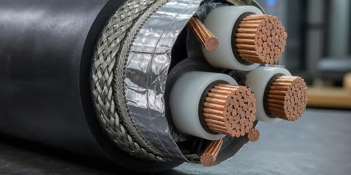
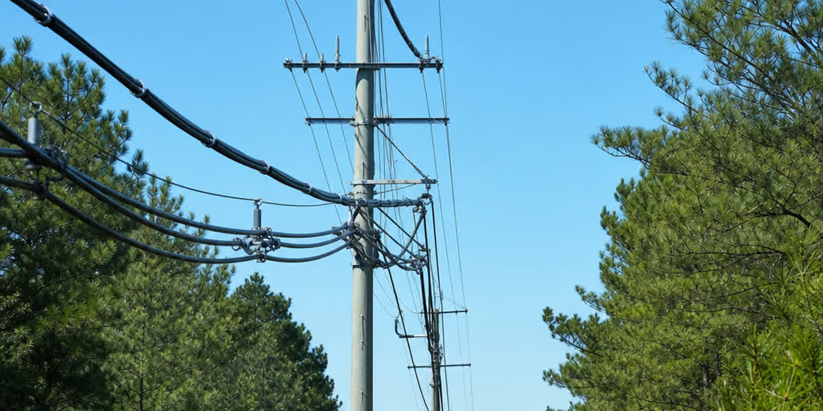
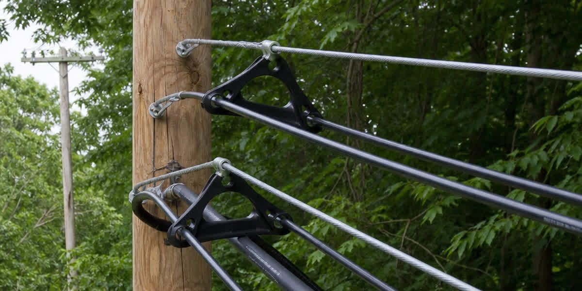
Vegetation contact is the single largest cause of outages on overhead distribution networks: in many utilities it accounts for 30–60% of all momentary interruptions. Tree Wire solves this with a weather-resistant extruded insulation layer (typically 2–4 mm of XLPE, HDPE, or EPR) over a conventional stranded conductor, which prevents flashover during temporary branch or animal contact. Spacer Cable takes the concept further by arranging three covered phase conductors in a triangular configuration around a galvanized steel messenger, held apart by insulating spacers at regular intervals.
The economics are compelling. Compared with bare overhead lines, a Tree Wire system can cut right-of-way width from 10–30 m down to 3–8 m, reduce tree-trimming frequency by up to 70%, and improve SAIFI reliability metrics by 60–80%. Compared with underground cable, it typically costs 40–60% less and is far faster to repair. But these benefits only materialize when the system is installed correctly: incorrect pulling tension, wrong spacer spacing, or damaged insulation during stringing will compromise the very reliability the product is bought to deliver.
This guide is the field companion to our Tree Wire / Spacer Cable Complete Technical Guide, which covers standards, specifications, and selection in depth. Here we focus on practical execution, referencing IEEE 1217, IEEE 524, ICEA S-70-547, IEC 60502-2, IEC 62230, ASTM B230/B231, and NESC C2.
Pre-Installation Preparation
Receiving and Storage
| Check item | Acceptance criteria |
|---|---|
| Drum condition | No broken lagging or impact damage; rotate on axis, never lay flat |
| Insulation surface | No cuts, abrasions, or deep score marks through the covering |
| Conductor ends | Both ends sealed against moisture ingress |
| Spacer hardware | Count and type match the bill of materials; no cracked bodies |
| Documentation | Mill test certificate with conductor size, insulation thickness, and spark-test record per IEC 62230 |
Storage rules: Store drums upright on a firm, drained surface. Keep the insulation protected from direct UV for extended periods — polyethylene coverings degrade under sustained sunlight, so store under cover or shade if the project is delayed beyond 6 months. Store away from heat sources; the covering shall not exceed 50°C during storage. At receipt, verify insulation thickness with a micrometer against the datasheet (typical values: 2.3–4.5 mm depending on voltage class).
Tools and Equipment Checklist
| Tool category | Items | Application note |
|---|---|---|
| Pulling | Conductor grips, swivels, pulling rope (synthetic), drum jacks | Use a swivel between rope and grip to prevent spin |
| Stringing | Stringing blocks or travelers, pole-top rollers | Block diameter ≥ 20× conductor OD to protect insulation |
| Tensioning | Brake or tensioner, dynamometer | Maintains stringing tension within limits |
| Spacers | Spacer installation tool, hot-stick (if energized) | Spacer spacing per design; see calculations below |
| Grounding | Ground sets, bonding cables | System grounding per NESC C2 and utility practice |
| Measurement | Sag tape, transit/theodolite, tension gauge | Sag verification after dead-ending |
| Safety | Insulated gloves, hard hats, fall protection | Live-line work requires utility authorization |
Installation Plan
Prepare a written plan covering: pulling direction and setup locations, section lengths between dead-ends, crossing protection (roads, railways, other lines), messenger anchor points, spacer interval schedule, and the sequence of work. Verify span lengths and pole heights against the construction drawings. Confirm weather conditions — stringing shall not proceed in winds above 30 km/h or during precipitation, because wet insulation and conductor movement increase damage risk.
Engineering Calculations
Stringing Tension Limits
The insulation adds weight and wind area but contributes no tensile strength. Pulling tension shall not exceed:
- Stringing tension: ≤ 20% of the conductor's rated breaking strength (RBS), or as specified by the design
- Maximum tension at final sag: per design, typically 15–18% RBS for covered conductors (slightly lower than bare conductor practice to protect the covering)
- Sidewall pressure at travelers: ≤ 400 kg/m (4 kN/m) to avoid insulation crushing — use larger-diameter blocks or multiple blocks in steep angle positions
Sag-Tension Calculation
Use the standard catenary or parabolic method with the covered conductor's composite weight per unit length (aluminum/steel strands + insulation). Key parameters:
| Parameter | Typical value | Notes |
|---|---|---|
| Conductor weight | +8–15% vs bare (insulation) | From manufacturer datasheet |
| Wind area | +15–25% vs bare | Insulation increases projected area |
| Initial modulus | ~60–70 GPa (AAC/AAAC cores) | Per IEEE 524 methods |
| Thermal elongation | 23×10⁻⁶ /°C (aluminum) | Covered conductors run cooler than bare in vegetation contact |
| Ice loading | Per local code (e.g., NESC heavy/medium/light) | Insulation reduces ice adhesion |
Rule of thumb: compute sag with the covered conductor weight, not the bare-core weight. A 20% weight increase with the same tension raises sag by roughly 20% — ignoring the insulation is the most common sag error on Tree Wire jobs.
Spacer Spacing
Spacer interval depends on phase spacing, conductor diameter, and short-circuit forces. IEEE 1217 provides the design method; typical values for 15 kV class systems are:
| Phase spacing (mm) | Typical spacer interval (m) |
|---|---|
| 150 | 4.5–6 |
| 200 | 6–8 |
| 300 | 8–10 |
Mid-span spacers prevent conductor clashing under galloping and short-circuit conditions. Verify the spacing schedule against the spacer manufacturer's rating for the fault current of the circuit.
Installation Procedure
Step 1: Site Preparation
Set up drum stands at the pulling end with the drum rotating off the top. Install the messenger wire first if the design uses a messenger-supported spacer cable — the messenger carries the mechanical load, so it must be tensioned to design value (typically 15–20% of messenger RBS) before phase conductors are pulled.
Step 2: Install Stringing Blocks
Place travelers or stringing blocks at every support. Use blocks with smooth, non-metallic liners rated for covered conductors — bare-conductor steel rollers will score the insulation. Verify block diameter ≥ 20× conductor OD.
Step 3: Pull the Pilot Line
Pull a synthetic pilot line (never steel cable directly against the insulation) through the blocks, then attach the conductor grip with a swivel. Use a pulling sock or Kellems grip over the insulation, never a bare-metal clamp on the covered surface.
Step 4: Tension Stringing
Pull the conductor at controlled tension using the tensioner brake. Monitor the dynamometer continuously; keep tension ≤ 20% RBS. Apply a temporary guard at every crossing (road, railway, communication line) per NESC C2 and IEEE 524. Walk the line behind the pull to check for snags and insulation damage.
Step 5: Sag and Clip-In
With the conductor at design tension and temperature, set sag by instrument (transit or sag board), not by eye. Dead-end the conductor at each anchor with approved dead-end hardware sized for the covered conductor — compression dead-ends must be installed with dies matched to the conductor's outer diameter including insulation, or with insulation removed at the termination point per manufacturer instructions. Clip the conductor into suspension clamps with cushioning inserts that protect the covering.
Step 6: Install Spacers
Install insulating spacers at the design intervals using the spacer installation tool. Spacers shall grip without cutting the insulation; check each spacer for correct engagement and orientation. In spacer-cable configurations, the three phase conductors must maintain the design phase spacing at every spacer position.
Step 7: Terminations and Connections
Strip insulation back to the manufacturer's specification at terminations. Use connectors rated for covered conductors — compression connectors for the bare section, with insulation-reducing or stress-control termination kits at the riser and transformer connections. Seal all exposed conductor ends with approved sealing compound or caps.
Step 8: Bonding and Grounding
Complete system grounding per NESC C2: ground the messenger at specified intervals (typically every 500 m and at dead-ends), bond the messenger to the neutral/ground system, and install arresters at riser poles. Verify grounding continuity with a low-resistance ohmmeter before energization.
⚠️ Safety callout: Tree Wire insulation is designed for momentary contact protection, NOT as a substitute for clearance or safe-work practices. Treat all covered conductors as energized until proven de-energized and grounded. Use insulated tools and hot-stick methods for live-line work.
Post-Installation Inspection & Testing
| Inspection item | Acceptance criteria |
|---|---|
| Insulation integrity | No cuts, abrasions, or punctures visible along the full run |
| Spark test (if applicable) | Insulation passes factory spark test per IEC 62230 before and after installation |
| Sag check | Within ±5% of design sag at reference temperature |
| Spacer placement | Intervals within ±10% of design; all spacers fully engaged |
| Dead-end and splice hardware | Correct installation, no loose parts |
| Grounding continuity | < 1 Ω to system ground at every grounding point |
| Clearances | Phase-to-phase and phase-to-ground per NESC C2 tables |
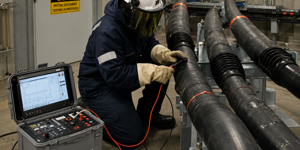
Before energization, perform a visual helicopter or drone patrol of the route, and where required by the utility, an insulation resistance (megger) test — readings below 100 MΩ/km at 1 kV DC warrant investigation.
Routine Maintenance Schedule
| Frequency | Activity |
|---|---|
| Monthly (first 6 months) | Patrol critical spans; check for vegetation contact and spacer damage |
| Quarterly | Trim vegetation to maintain minimum clearance; check messenger tension |
| Annually | Infrared scan of splices, dead-ends, and terminations; check sag trends |
| Every 3 years | Detailed pole-top inspection; verify spacer engagement; check for insulation tracking or UV damage |
| Every 5 years | Full line survey; sample-test insulation condition; verify grounding continuity |
| After major storms | Emergency patrol; check for conductor clash, spacer loss, and damaged insulation |
Trend analysis: record sag and tension readings annually. A sag increase of more than 5% from baseline with no temperature change indicates conductor creep or anchor slip — investigate before it becomes a clearance violation.
Troubleshooting Common Issues
| Problem | Likely cause | Solution |
|---|---|---|
| Outage during vegetation contact | Insulation damaged at installation (scored by roller or grip) | Patrol and repair with approved splice/cover kit |
| Conductor clash in wind | Spacer spacing too wide or spacers missing | Re-install spacers at design intervals |
| Insulation tracking on surface | Contamination + moisture on aged covering | Clean or replace section; consider silicone coating |
| Sag too high | Wrong weight used in sag calculation (bare instead of covered) | Re-compute and re-tension |
| Messenger sag excessive | Messenger under-tensioned at install | Re-tension messenger to design |
| Spacer body cracking | UV degradation or wrong spacer rating | Replace with UV-stabilized spacer of correct rating |
| Radio noise / corona | Sharp hardware edges or damaged insulation at terminations | Dress hardware; repair termination |
Safety Considerations
| Hazard | Precaution |
|---|---|
| Induced voltage | Ground both sides of the work section; use personal grounds |
| Energized conductors (assumed live) | Verify de-energized, test, and ground before contact |
| Falls from height | Full fall protection; ladder and bucket-truck procedures |
| Pulling tension failures | Keep personnel clear of the pull zone; use rated hardware |
| Insulation damage during handling | Use proper grips, blocks, and rollers; inspect before pulling |
| Live-line work | Authorized hot-stick crews only; insulated tools rated for system voltage |
FAQ
1. Can Tree Wire be installed like regular ACSR conductor? Not exactly. The insulation requires larger-diameter stringing blocks (≥ 20× OD), pulling grips over the covering rather than bare-metal clamps, and slightly lower stringing tension (≤ 20% RBS) to avoid insulation damage. The sag calculation must use the covered conductor's composite weight, not the bare-core weight.
2. What is the maximum span for Tree Wire / Spacer Cable? Typical spans are 60–150 m for 15 kV class systems. Longer spans are possible with larger conductors and messengers, but spacer-cable systems are generally designed for distribution spans rather than transmission distances. Verify sag and clash criteria with the design engineer.
3. How often should tree trimming be done with Tree Wire? Far less frequently than with bare lines — typically 3–5 times less often. Because the insulation prevents flashover during momentary contact, trimming is needed only to prevent sustained rubbing and to maintain statutory clearances. Many utilities report 60–80% fewer vegetation-related interruptions.
4. Does the insulation need to be removed at every connection? Yes, at terminations and connections the insulation is stripped back to manufacturer specification so the connector can make metal-to-metal contact. Use approved termination kits and sealing compounds to protect the exposed conductor ends.
5. How do I detect damaged insulation after installation? Visual patrol (ground, helicopter, or drone) is the primary method, supplemented by an insulation resistance test (≥ 100 MΩ/km at 1 kV DC). Spark testing per IEC 62230 can be applied to the conductor before installation and in factory reels.
6. What is the design life of a Tree Wire system? 30–40 years with proper installation and maintenance. UV-stabilized insulation, correct spacer selection, and routine vegetation management are the main factors that determine whether the system reaches full life.
7. Are Tree Wire and ABC cable the same thing? No. ABC cable (Aerial Bundled Cable) is a low-voltage (< 1 kV) bundled cable with all phases twisted together around a messenger, while Tree Wire is a medium-voltage (5–69 kV) covered conductor used in spaced configurations. They serve different voltage classes and use different hardware.
8. What standards apply to Tree Wire installation? The primary standards are IEEE 1217 (spacer cable design and installation), IEEE 524 (overhead conductor installation), ICEA S-70-547 (weather-resistant covered conductors), IEC 60502-2 (MV extruded insulation), and NESC C2 (clearances and safety). Regional standards include BS 7870-5 / ENA TS 43-92 (UK) and AS/NZS 3599 (Australia/NZ).
References and Standards
| Standard | Description |
|---|---|
| IEEE 1217 | Guide for the Design and Installation of Spacer Cable Systems |
| IEEE 524 | Guide for the Installation of Overhead Transmission Line Conductors |
| ICEA S-70-547 | Weather-Resistant Polyethylene Covered Conductors |
| IEC 60502-2 | Power Cables with Extruded Insulation for Rated Voltages 6–30 kV |
| IEC 62230 | Electric Cables — Spark-Test Method |
| ASTM B230 / B231 | Aluminum 1350 Wire / Conductors |
| NESC (ANSI C2) | National Electrical Safety Code — clearances and safety |
| BS 7870-5 / ENA TS 43-92 | UK covered conductor standards |
| AS/NZS 3599 | Australian/NZ aerial bundled and covered conductor systems |
About SiTong Cable
SiTong Cable manufactures Tree Wire and Spacer Cable to international standards (IEEE, IEC, ASTM, BS), with insulation thicknesses and conductor constructions tailored to utility specifications worldwide. Our engineering team supports projects from conductor selection through installation guidance and field troubleshooting. For a quotation, technical datasheets, or installation support, contact our team.
👉 Browse our Tree Wire product range 👉 Tree Wire / Spacer Cable: Complete Technical Guide 👉 Contact our team
📬 Sales inquiries: sales@sitongcable.com | 📞 Phone: +86-371-69176007
This guide was prepared by the SiTong Cable engineering team. All technical data references IEEE 1217, IEEE 524, ICEA S-70-547, IEC 60502-2, IEC 62230, ASTM B230/B231, and NESC C2.