AAAC Installation & Maintenance: Complete Field Guide for Overhead Transmission Lines
AAAC Installation & Maintenance: Complete Field Guide for Overhead Transmission Lines
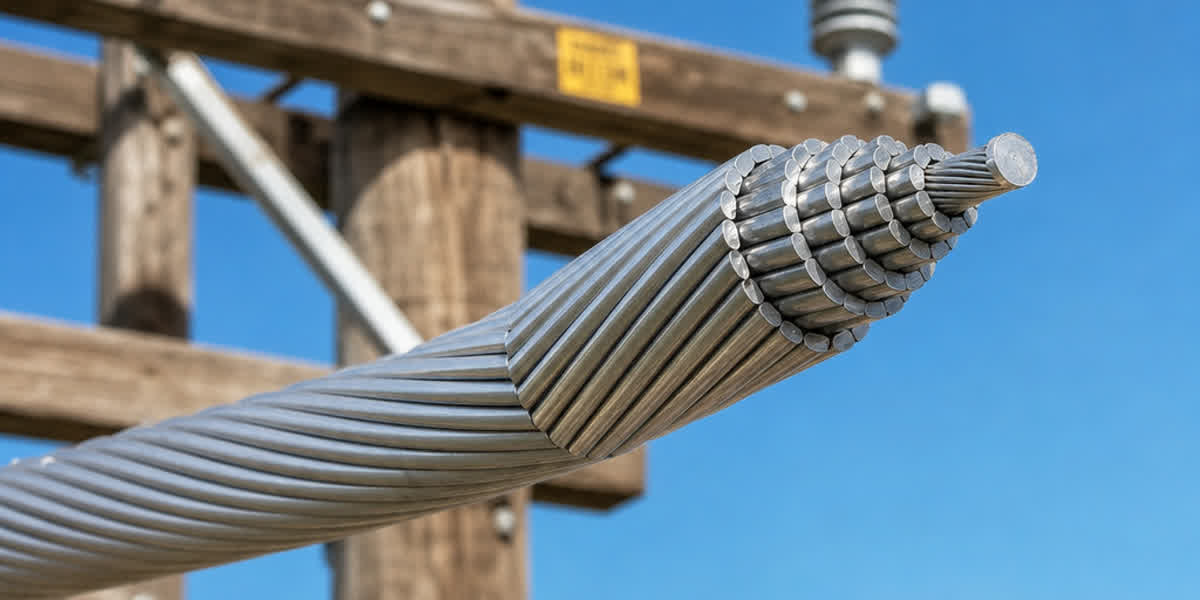
All Aluminum Alloy Conductor (AAAC) is widely used in overhead transmission and distribution lines for its excellent strength-to-weight ratio, superior corrosion resistance, and low electrical losses. Proper installation and maintenance are crucial to achieving the 40+ year service life that AAAC systems are designed to deliver. This field guide provides step-by-step installation procedures, engineering calculations, inspection protocols, and troubleshooting guidance for field engineers, linemen, and project managers working with AAAC conductors.
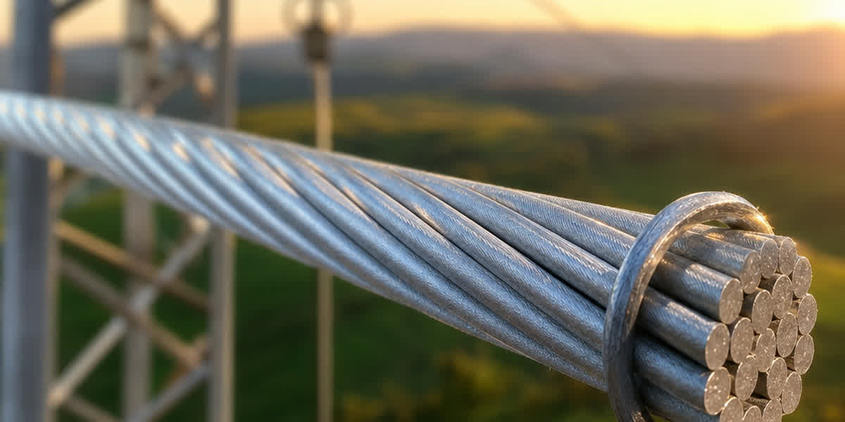
💡 Key difference from AAC: AAAC is made from heat-treated aluminum-magnesium-silicon alloy (6201-T81), giving it approximately twice the tensile strength of AAC while maintaining comparable conductivity (52.5%–53.5% IACS). This fundamentally changes installation parameters — higher pulling tensions, different compression specifications, and distinct sag-tension behavior.
Pre-Installation Preparation
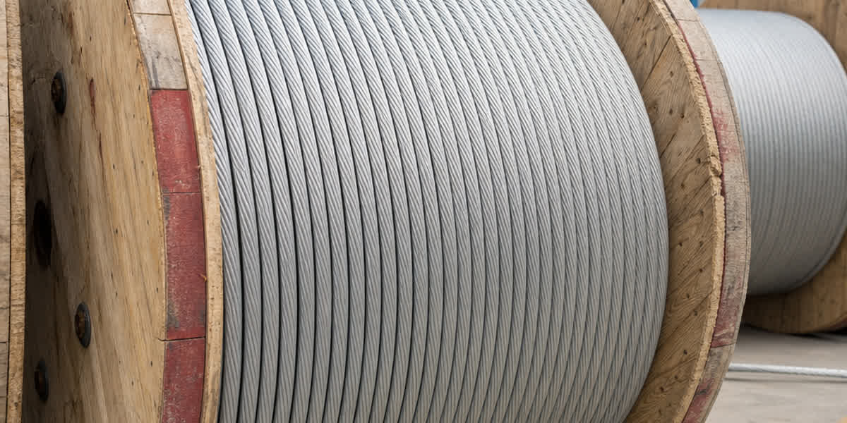
Receiving and Storage
| Procedure | Requirements | Notes |
|---|---|---|
| Visual inspection | Check drums for damage, bent flanges, broken lagging | Photograph damage before unloading |
| Conductor inspection | Unreel 3–5 turns, check for kinks, birdcaging, abrasion | Reject drum if strand damage exceeds 3% |
| Storage position | Drums on end (vertical) on hard, dry surface | Never store on side — ovalizes coils |
| Storage duration | < 6 months: outdoor, covered with breather tarpaulin | > 6 months: indoor, 10–30°C, < 70% RH |
| Rotation schedule | First-in, first-out (FIFO) | Track drum receipt date on drum tag |
Tools and Equipment Checklist
| Category | Equipment | Application |
|---|---|---|
| Pulling | Bullwheel puller (8–12 t capacity), tensioner, pilot line winder | Main tension stringing |
| Splicing | Hydraulic compressor (≥ 100 t), full-tension splice dies, repair sleeve dies | AAAC requires 15–20% higher compression pressure than AAC — verify tool calibration |
| Hot-line | Hot-line compression tool, insulated shotgun sticks | Live-line repair only for conductors ≤ 66 kV |
| Measurement | Sag scope, dynamometer (5 t), laser rangefinder, tension load cell | Sag-tension verification |
| Grounding | Traveling grounds (3 sets), cluster bar, personal grounding sets | Induction voltage protection |
| Accessories | Preformed armor rods, vibration dampers (Stockbridge type), spacer dampers | Per dynamic design |
⚠️ AAAC-specific: Compression dies for AAAC must be verified against the alloy's higher hardness (BHN 55–65 vs. AAC's BHN 15–20). Using AAC-rated dies will cause incomplete compression. Always check manufacturer die assignment chart.
Installation Plan
- Determine section lengths from structure spotting plan (typical: 300–500 m span)
- Identify setup locations for puller and tensioner — at least 10 m from last structure
- Plan crossing protection (bucket trucks, nets, guard structures for road/rail crossings)
- Establish radio communication between puller and tensioner operators
- Confirm weather limits: wind < 25 km/h, no precipitation, ambient temp within –10°C to +40°C
Engineering Calculations
Design Parameters
| Parameter | Symbol | Typical Range | Standard |
|---|---|---|---|
| Rated tensile strength | RTS | 15–200 kN | IEC 61089 / ASTM B399 |
| Max installation tension | 20% RTS (normal), 25% RTS (short-term) | — | IEEE 524 |
| Initial sag (10% RTS, 15°C) | — | 0.3–1.5 m for 300 m span | IEC 61089 |
| Creep at 10% RTS, 10 years | — | 0.01–0.03% strain | CIGRE TB 324 |
| Thermal expansion coefficient | α | 23.0 × 10⁻⁶ /°C | ASTM B399 |
| Elastic modulus | E | 62 GPa | ASTM B399 |
Sag-Tension Computation
The ruling span method (catenary approximation) is used for AAAC:
S = (w × L²) / (8 × H)
Where:
- S = sag at mid-span (m)
- w = conductor weight per unit length (kg/m)
- L = span length (m)
- H = horizontal tension (N)
AAAC-specific consideration: Because AAAC is a homogeneous alloy (no steel core), tension is uniformly distributed across all strands. Unlike ACSR, there is no steel-core/AAC-strand load sharing. This simplifies sag-tension calculation to a single-material model.
Creep compensation: AAAC exhibits slightly more creep than ACSR but less than AAC. Use CIGRE TB 324 creep curves for the specific alloy. Typical creep allowance: 0.02% additional strain over 10 years at 15% RTS.
Thermal Effects
| Condition | Sag Increase (300m span, 240 mm² AAAC) |
|---|---|
| 15°C → 40°C (summer) | +0.35 m |
| 15°C → 75°C (max continuous) | +1.1 m |
| 15°C → 100°C (emergency) | +1.5 m |
| Ice loading (12 mm radial) | +0.08 m (additional from weight) |
Check clearance to ground under worst-case combination: max temperature + ice loading.
Installation Procedure
Step 1: Setup and Pilot Line
- Position tensioner at far end, puller at near end
- Install traveling grounds on first three structures on both pull and tension ends
- String pilot line (nylon / fiberglass — 8–12 kN breaking strength)
- Attach swivel to prevent twist transfer
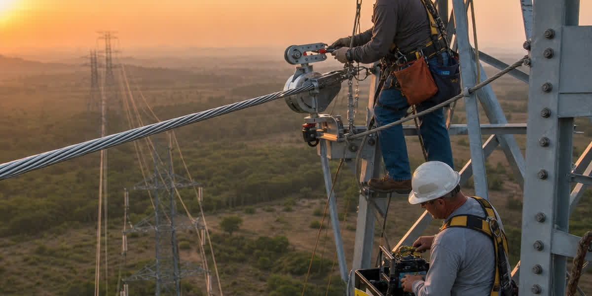
Step 2: Tension Stringing
| Phase | Action | Requirements |
|---|---|---|
| Initial pull | Low tension (2–3 kN) to clear ground | Speed ≤ 5 km/h |
| Mid-section | Ramp tension to 15–20% RTS | Speed ≤ 8 km/h |
| Final sections | Full installation tension (20% RTS max) | Verify dynamometer every 10 spans |
| Sag adjustment | Final sag to ±2% of design target | Allow 30 min settling before measuring |
⚠️ AAAC warning: Never exceed 25% RTS during stringing. AAAC has approximately half the breaking strength of equivalent-size ACSR — over-tensioning causes permanent strand elongation (necking) visible as "birdcaging" at dead-end points.
Step 3: Clipping and Dead-Ending
- Transfer conductor from travelers to suspension clamps
- Install preformed armor rods at suspension points (required for spans > 200 m)
- Dead-end with full-tension compression dead-ends
Compression dead-end specification (AAAC):
| Conductor Size | Die Size | Compression Stroke | Pressure | Number of Crimps |
|---|---|---|---|---|
| 50–95 mm² | Matched to O.D. | 2 strokes | 65–75 MPa | 2 per side |
| 120–240 mm² | Matched to O.D. | 2 strokes | 70–85 MPa | 3 per side |
| 300–400 mm² | Matched to O.D. | 3 strokes | 75–90 MPa | 4 per side |
| > 400 mm² | Matched to O.D. | 3 strokes | 80–95 MPa | 4 per side |
💡 Field tip: AAAC's alloy hardness means the compression die must be 0.2–0.5 mm smaller than AAC dies for the same nominal O.D. Verify die assignment against the manufacturer's chart — do not substitute AAC dies.
Step 4: Splicing
Full-tension splice procedure: 1. Strip conductor ends to manufacturer-specified length 2. Insert both ends into splice sleeve (opposite directions) 3. Mark compression zones 4. Compress center zone first, then outer zones — alternating sides 5. Check slip strength ≥ 95% RTS (acceptance sample: 1 per 50 splices)
Repair sleeve procedure (non-tension): 1. Remove damaged strands (max 3 adjacent strands, < 20% of total strands) 2. Install repair sleeve over damaged area 3. Compress from center outward
Step 5: Accessories Installation
| Accessory | Installation Torque / Method | Purpose |
|---|---|---|
| Stockbridge dampers | 40–50 N·m clamp bolt torque | Aeolian vibration control |
| Spacer dampers (bundle) | 35–45 N·m per clamp | Sub-conductor oscillation damping |
| Corona rings | Manufacturer spec | ≤ 132 kV: optional; ≥ 220 kV: required |
| Arcing horns | Fixed gap, parallel to insulator string | Lightning discharge path |
Post-Installation Inspection & Testing
| Inspection Item | Acceptance Criteria | Method |
|---|---|---|
| Sag accuracy | Within ±2% of design target | Theodolite or laser rangefinder |
| Conductor clearance | ≥ minimum per applicable code (NESC, IEC) | Direct measurement |
| Splice resistance | ≤ 1.2 × equivalent conductor resistance | Micro-ohmmeter (DC) |
| Splice temperature rise | ≤ 5°C above adjacent conductor at rated load | Thermal imaging |
| Corona discharge | No visible corona at 110% rated voltage (dry conditions) | UV camera (CISPR 18-2) |
| Compression gauge marks | Visible, centered, within tolerance | Visual |
| Grounding continuity | < 5 Ω to ground per structure | Ground megger |
Routine Maintenance Schedule
| Frequency | Activity | Notes |
|---|---|---|
| Monthly (first year) | Visual patrol — focus on splices and dead-ends | New lines exhibit initial settling |
| Semi-annual | Thermal imaging of all splices and dead-ends | Compare against baseline from post-installation test |
| Annual | Sag measurement on 3 representative spans | Check against design curves |
| Annual | Vibration damper inspection | Replace loose, cracked, or displaced dampers |
| Every 2 years | Full line patrol (helicopter or drone) | Corrosion check in coastal/industrial zones |
| Every 5 years | Sample splice pull-test (1 per 100 splices) | Verify ≥ 95% RTS remains |
| Every 10 years | Conductor sample lab test (1 per 50 km) | Check tensile strength retention, corrosion depth |
Troubleshooting Common Issues
| Problem | Likely Cause | Solution |
|---|---|---|
| Excessive sag (+5%) | Over-tension during stringing or creep beyond prediction | Re-sag if clearance is compromised; otherwise monitor annually |
| Splice temperature > 5°C above baseline | Incomplete compression or corrosion | Replace splice — re-compression is not reliable for AAAC alloy |
| Birdcaging near dead-end | Over-tension during stringing or wind-induced vibration | Cut back to unaffected strand, re-terminate |
| Strand breakage (1–2 strands) | Galloping fatigue or vibration | Install additional dampers; repair with sleeve |
| Corrosion pitting (coastal) | Salt spray attack on alloy surface | Apply corrosion-inhibiting grease at splices, install anti-corona rings |
| Low corona inception voltage | Sharp edges on hardware or damaged strands | File smooth edges; replace damaged strands |
| Vibration damper displacement | Incorrect clamp torque (too low) | Re-torque to 40–50 N·m per manufacturer spec |
Safety Considerations
| Hazard | Precaution |
|---|---|
| Induced voltage on de-energized line | Install traveling grounds at puller, tensioner, and every 3 structures |
| Falling from height | Full-body harness with double lanyard; 100% tie-off below 2 m |
| Pulling cable tension | Stay outside tension zone (1.5× span length from puller); use tag line |
| Hydraulic tool pinch points | Never place hands near compression dies during cycle; use automatic pressure relief |
| Live-line work | Minimum approach distance per IEC 61472: 0.9 m for 66 kV, 1.5 m for 220 kV |
| Weather | Halt work if lightning within 10 km; hot-line work suspended above 40°C ambient |
Frequently Asked Questions
-
What is the maximum installation tension for AAAC? The recommended maximum stringing tension is 20% of RTS for normal conditions and 25% for short-term (≤ 30 minutes) situations such as crossing obstacles. Exceeding these limits risks permanent strand elongation (necking) or birdcaging.
-
Can I use the same compression dies for AAAC and AAC? No. AAAC (6201-T81 alloy, BHN 55–65) requires dies 0.2–0.5 mm smaller than AAC (1350 alloy, BHN 15–20) for the same nominal conductor diameter. Using AAC dies on AAAC will produce incomplete compression and splice failure under load.
-
How does AAAC sag-tension differ from ACSR? AAAC is a homogeneous material (no steel core), so its sag-tension calculation uses a single elastic modulus (62 GPa) and thermal expansion coefficient (23 × 10⁻⁶ /°C). ACSR requires a composite model because the steel core carries a significant portion of the load. AAAC sags more at high temperatures than equivalent-size ACSR.
-
What is the expected service life of an AAAC installation? With proper installation and routine maintenance, AAAC typically achieves 40–50 years of service life. Corrosion-prone environments (coastal, industrial) may reduce this to 25–35 years without protective measures.
-
How often should splices be inspected? Splices should be thermally imaged semi-annually for the first 2 years (when most failures develop), then annually. An alarming temperature rise (> 10°C above baseline) indicates imminent failure and requires immediate replacement.
-
Can AAAC be installed in coastal environments? Yes. AAAC's aluminum-magnesium-silicon alloy offers superior corrosion resistance compared to ACSR (no galvanic corrosion between steel and aluminum). However, all splices and dead-ends should be treated with corrosion-inhibiting grease, and routine cleaning with deionized water is recommended every 3–5 years.
-
What span lengths are typical for AAAC? AAAC is suitable for spans from 100 m (distribution) to 500 m (transmission). For longer spans, ACAR or ACSR may be more economical due to higher strength. The maximum practical span for AAAC at 20% RTS is approximately 450–500 m depending on conductor size.
-
Is live-line work possible on AAAC conductors? Yes, up to 66 kV with hot-line tools. For higher voltages, bare-hand (conductive suit) methods with minimum approach distances per IEC 61472 are required. AAAC's homogeneous surface (no steel core exposure) reduces corona compared to ACSR of equivalent size.
References and Standards
| Standard | Description |
|---|---|
| ASTM B399/B399M | Standard Specification for Concentric-Lay-Stranded Aluminum-Alloy 6201-T81 Conductors |
| IEC 61089 | Round wire concentric lay overhead electrical stranded conductors |
| IEEE 524 | Guide to the Installation of Overhead Transmission Line Conductors |
| IEEE 563 | Guide on Conductor Maintenance and Inspection |
| IEEE 738 | Calculating Current-Temperature of Bare Overhead Conductors |
| IEC 60826 | Design criteria of overhead transmission lines |
| IEC 61284 | Overhead lines — Requirements and tests for fittings |
| IEC 61238-1 | Compression and mechanical connectors for power cables |
| CIGRE TB 324 | Sag-Tension Calculation Methods for Overhead Lines |
| ASTM B398 | Standard Specification for Aluminum-Alloy 6201-T81 Wire for Electrical Purposes |
| CISPR 18-2 | Radio interference characteristics of overhead power lines |
| IEC 61472 | Live working — Minimum approach distances |
About / Contact
This guide was prepared by the SiTong Cable engineering team based on field experience and international standards. SiTong Cable manufactures a comprehensive range of AAAC conductors to ASTM B399, IEC 61089, and BS 3242 standards, serving utilities, renewables, and EPC contractors worldwide.
👉 Browse our AAAC product range 👉 AAAC Complete Technical Guide — specifications, selection methodology, applications 👉 Contact our engineering team for technical support or project-specific recommendations
📬 Sales inquiries: sales@sitongcable.com | 📞 Phone: +86-371-69176007