Tree Wire / Spacer Cable: Complete Technical Guide to Covered Conductors for Overhead Distribution (Standards, Specifications, Installation & Maintenance)
Tree Wire / Spacer Cable: Complete Technical Guide to Covered Conductors for Overhead Distribution (Standards, Specifications, Installation & Maintenance)
Tree Wire (also known as Spacer Cable or Covered Conductor) is a medium-voltage overhead distribution system that uses weather-resistant polymeric insulation over stranded conductors. Unlike bare overhead lines, Tree Wire prevents flashovers from temporary vegetation contact, making it the optimal solution for distribution in tree-lined areas, environmentally sensitive zones, and regions with high bird or wildlife activity. This comprehensive technical guide covers industry standards (IEEE, IEC, ASTM, BS), conductor specifications, system configurations, installation best practices, maintenance procedures, and international applications.
1. What is Tree Wire / Spacer Cable?
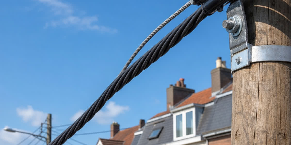
Tree Wire (covered conductor) is an insulated or semi-insulated overhead conductor rated for medium voltage (typically 5 kV – 69 kV). It features a statically extruded polymeric insulation layer (commonly XLPE, HDPE, or EPR) over a conventional stranded conductor core. The insulation provides electrical isolation sufficient to prevent flashovers during momentary contact with tree branches, animals, or foreign objects.
Spacer Cable is a system configuration that uses Tree Wire conductors arranged in a triangular or spaced configuration, held apart by spacers along a supporting messenger wire. This system combines the reliability of underground cable with the economic advantages of overhead construction.
1.1 Why Choose Tree Wire Over Bare Conductor?
| Factor | Bare Overhead Conductor | Tree Wire / Spacer Cable |
|---|---|---|
| Vegetation contact | Flashover → outage | Momentary rub, no flashover |
| Wildlife interference | High (birds, squirrels cause faults) | Low (insulated) |
| Line spacing | Wide (phase-to-phase clearance critical) | Compact (spacers maintain small, fixed separation) |
| Right-of-way width | 10–30 m typical | 3–8 m typical |
| Storm resilience | Moderate (conductors can clash) | High (spacers prevent clashing) |
| Visual impact | Prominent | Less intrusive (compact) |
| Maintenance cost | Regular tree trimming required | Reduced trimming frequency |
| Reliability (SAIFI) | Baseline | 60–80% fewer momentary interruptions |
1.2 Key Terminology
- Covered Conductor (CC): Conductor with a thin to medium insulation layer (2–4 mm), designed for medium-voltage distribution
- Tree Wire: Colloquial term for covered conductor in tree-line applications
- Spacer Cable: System configuration with spaced covered conductors on a messenger
- Aerial Bundled Cable (ABC): Low-voltage (<1 kV) bundled cables — not to be confused with Tree Wire
2. Industry Standards and Specifications
Tree Wire / Spacer Cable must comply with multiple international standards depending on the jurisdiction:
2.1 Primary International Standards
| Standard | Title | Scope |
|---|---|---|
| IEEE 524 | Guide for the Installation of Overhead Transmission Line Conductors | General installation practices |
| IEEE 1217 | Guide for the Design and Installation of Spacer Cable Systems | Spacer cable system design |
| IEC 60502-2 | Power Cables with Extruded Insulation for Rated Voltages 6–30 kV | Medium-voltage cable construction |
| IEC 62230 | Electric Cables — Spark-Test Method | Insulation integrity testing |
| ASTM B230/B231 | Aluminum 1350 Conductors | Conductor material specs |
| ASTM B498 | Zinc-Coated (Galvanized) Steel Core Wire for Aluminum Conductors | Steel reinforcing |
| BS 7870 | LV and MV Polymeric Insulated Cables | UK standard for covered conductors |
| ICEA S-70-547 | Weather-Resistant Polyethylene Covered Conductors | Weather-resistant covering specs |
| NESC (ANSI C2) | National Electrical Safety Code | Clearance and safety requirements |
2.2 Regional Standards by Country
| Region | Governing Standard | Key Requirements |
|---|---|---|
| United States | IEEE 1217, NESC C2, ICEA S-70-547 | 5–46 kV, XLPE/HDPE insulation, messenger support |
| United Kingdom | BS 7870-5, ENA TS 43-92 | 11–33 kV, weather-resistant XLPE |
| EU / IEC | IEC 60502-2, HD 620 S1 | 6–36 kV, extruded insulation |
| Australia / NZ | AS/NZS 3599, AS 4132 | 11–33 kV, covered conductor on spacers |
| Middle East | IEC + IEEE hybrid | 15–33 kV, sand/salt resistant XLPE |
| Southeast Asia | IEC 60502-2, local utility specs | 12–24 kV, high UV-resistant insulation |
3. Conductor Types and Construction
3.1 Core Conductor Options
| Type | Material | Application | Standards |
|---|---|---|---|
| AAC (All Aluminum Conductor) | 1350-H19 aluminum | Short spans, low-load areas | ASTM B230/B231 |
| AAAC (All Aluminum Alloy Conductor) | 6201-T81 alloy | Longer spans, higher strength | ASTM B398/B399 |
| ACSR (Aluminum Conductor Steel Reinforced) | 1350-H19 + galvanized steel | Heavy-load spans, ice zones | ASTM B230/B231 + B498 |
| ACAR (Aluminum Conductor Alloy Reinforced) | 1350-H19 + 6201-T81 | Balanced strength/conductivity | ASTM B524 |
3.2 Insulation Systems
| Insulation Material | Temperature Rating | Dielectric Strength | UV Resistance | Typical Application |
|---|---|---|---|---|
| XLPE (Cross-linked Polyethylene) | 90°C continuous, 130°C emergency | High | Excellent (with carbon black) | Most common — all climates |
| HDPE (High-Density Polyethylene) | 75°C continuous | Medium-High | Excellent | Dry climates, cost-sensitive |
| EPR (Ethylene Propylene Rubber) | 90°C continuous, 140°C emergency | High | Good | Wet/humid environments |
| XLPO (Cross-linked Polyolefin) | 105°C continuous | High | Excellent | High-temperature industrial |
Insulation thickness by voltage class (IEEE 1217 typical):
| Voltage Class (kV) | Insulation Thickness (mm) | Test Voltage (kV) |
|---|---|---|
| 5–8 | 2.3–3.0 | 20 |
| 15–25 | 3.0–4.5 | 45 |
| 35 | 4.5–5.5 | 60 |
| 46–69 | 5.5–7.0 | 80 |
3.3 Complete Construction Sequence
(From inside out)
1. Stranded conductor core (AAC, AAAC, ACSR, or ACAR)
2. Semi-conductive strand shield (for voltage >15 kV)
3. Insulation layer (XLPE / HDPE / EPR)
4. Semi-conductive insulation shield (for >15 kV systems)
5. Weather-resistant jacket (optional, for UV/moisture protection)
4. Spacer Cable System Configuration
4.1 System Components
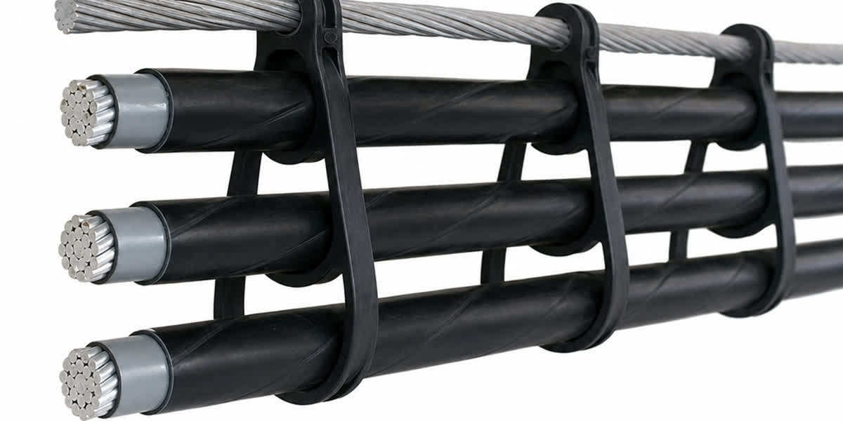
        ┌─────────────────────────────────┐
        │  Messenger / Support Wire        │
        │  (Galvanized steel, 7–12 mm)     │
        └─────────────────────────────────┘
                  │   │   │
               ╔══╧═══╧═══╧══╗
               ║   Spacers    ║  (Installed every 20–40 ft / 6–12 m)
               ╚══╤═══╤═══╤══╝
                  │   │   │
        ┌─────────┴───┴───┴─────────┐
        │  Phase A  Phase B  Phase C │
        │  Tree Wire Conductors      │
        └───────────────────────────┘
| Component | Material | Specification |
|---|---|---|
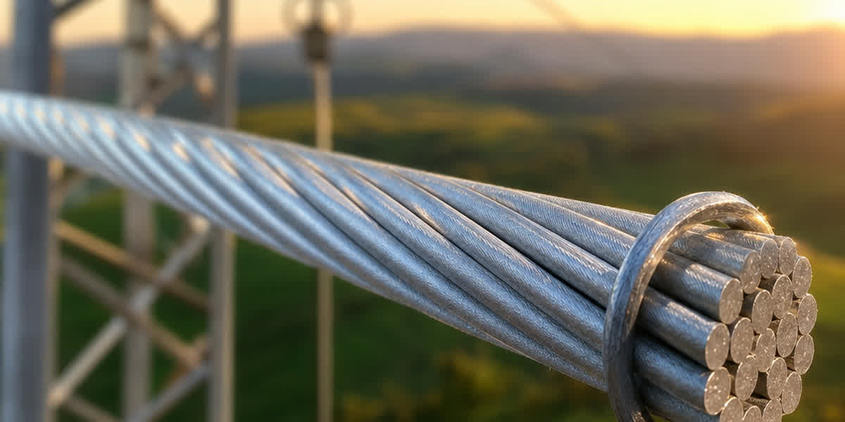
| Messenger Wire | Galvanized steel (7-wire strand) | ASTM A475 / BS 183 |
| Spacers | UV-stabilized polymer (polypropylene/PE) | IEEE 1217 compliant |
| Spacer interval | 20–40 ft (6–12 m) | Varies by span length × wind loading |
| Phase spacing | 6–12 inches (150–300 mm) | Varies by voltage class |
| Dead-end assemblies | Preformed helical rods + polymer insulators | IEEE 524, NESC |
4.2 Comparison: Spacer Cable vs Traditional Bare Conductor
| Parameter | Spacer Cable System | Traditional Bare Overhead |
|---|---|---|
| Right-of-way width | 3–8 m | 10–30 m |
| Phase spacing | 150–300 mm | 600–3000 mm |
| Tree trimming frequency | Every 5–10 years | Annual or bi-annual |
| Outages from vegetation | 80% fewer | Baseline |
| Lightning performance | Withstands indirect strikes | Direct exposure |
| Construction cost | 15–25% higher than bare | Lower |
| Lifetime maintenance cost | 30–50% lower | Higher |
5. Applications and Use Cases
5.1 Primary Applications
- Tree-Lined Residential and Urban Areas
- Reduces outage frequency from vegetation contact by 60–80%
- Eliminates need for wide tree-trimming corridors
-
Complies with urban aesthetic requirements
-
Environmentally Sensitive Zones
- Forests, nature reserves, bird migration corridors
- Wildlife protection (birds, squirrels, monkeys in tropical regions)
-
Reduced visual footprint vs bare conductors
-
Areas with High Bird/Wildlife Activity
- Insulated conductors prevent phase-to-phase faults from animal bridges
-
Spacer configuration prevents conductor clashing from large birds
-
Coastal and High-Wind Regions
- Compact configuration reduces wind loading
- Spacers prevent galloping and conductor clashing
-
Salt-resistant XLPE insulation available for coastal environments
-
Restricted Right-of-Way Corridors
- Narrower right-of-way requirement (3–8 m vs 10–30 m)
- Ideal for densely built-up areas and narrow lanes
5.2 Recommended Voltage Classes by Application
| Application | Primary Voltage | Insulation Type | Typical Span |
|---|---|---|---|
| Residential distribution | 5–15 kV | XLPE, 3.0 mm | 60–120 m |
| Urban/suburban feeders | 15–25 kV | XLPE, 3.0–4.5 mm | 50–100 m |
| Industrial supply | 25–35 kV | XLPE, 4.5–5.5 mm | 80–150 m |
| Rural long-span | 15–35 kV | ACSR + XLPE, 4.5 mm | 100–200 m |
| Sub-transmission | 46–69 kV | XLPE/EPR, 5.5–7.0 mm | 150–300 m |
6. Installation Best Practices
6.1 Pre-Installation Checks
- [ ] Verify conductor and insulation type match project specifications
- [ ] Perform DC high-voltage test on each drum (per IEEE 400)
- [ ] Check messenger wire for corrosion or damage
- [ ] Inspect spacers for UV degradation and cracks
- [ ] Confirm pulling equipment is calibrated (tension ≤ 20% of conductor rated breaking strength)
- [ ] Temperature and humidity within installation limits (-10°C to 50°C, <85% RH)
6.2 Stringing and Pulling
| Parameter | Recommendation |
|---|---|
| Maximum pulling tension | 15–20% of conductor RBS (rated breaking strength) |
| Pulling speed | 0.5–1.5 m/s (1.5–5 ft/s) |
| Bend radius (minimum) | 20× conductor diameter |
| Lubrication | Water-based polymer lubricant (not petroleum-based) |
| Swivels | Required to prevent insulation twisting |
| Running ground | Required for electrostatic discharge protection |
6.3 Spacer Installation
- Install messenger wire — tensioned to 10–15% of rated breaking strength with 2–4% sag at 15°C
- Set first spacer at dead-end assembly, 1–2 m from termination
- String Tree Wire conductors — maintain equal tension per phase (±5% tolerance)
- Clip conductors into spacers — verify insulation is clean and undamaged at contact points
- Install spacers at uniform intervals (typically 20–40 ft / 6–12 m)
- Terminate at far end — use preformed helical dead-end fittings designed for covered conductors
6.4 Splicing and Termination
- Splices: Preformed tension splices with insulation re-establishment kit (cold shrink or heat shrink)
- Terminations: Polymer surge arrestors + insulated dead-end assemblies per IEEE C62.11
- Stress relief: Semi-conductive stress cones required for terminations >15 kV
6.5 Post-Installation Testing
| Test | Standard | Acceptance Criteria |
|---|---|---|
| DC hi-pot (insulation) | IEEE 400, IEC 60502 | 80% of factory test voltage × 15 min |
| Visual + corona inspection | IEEE 524 | No corona discharge at night/in fog |
| Conductor tension verification | Sag chart | ±3% of design sag |
| Insulation integrity (spark test) | IEC 62230 | No breakdown at specified voltage |
7. Maintenance and Inspection
7.1 Inspection Schedule
| Frequency | Inspection Items |
|---|---|
| Monthly | Visual scan from ground — check for broken spacers, sagging, vegetation encroachment |
| Quarterly | Thermal imaging of splices and terminations — hotspots indicate loose connections |
| Annually | Detailed line patrol — check spacers, messenger tension, insulation condition, bird nesting |
| 5-Year | Complete system audit — 100% spacer inspection, tension measurement, insulation spark test |
7.2 Common Issues and Solutions
| Issue | Cause | Solution |
|---|---|---|
| Insulation tracking | Surface contamination + moisture | Clean with isopropyl alcohol; apply silicone anti-tracking coating |
| Spacer cracking | UV degradation >10 years | Replace with UV-stabilized polymer spacers |
| Messenger corrosion | Coastal/salt environment | Replace with hot-dip galvanized or stainless steel messenger |
| Conductor sagging | Overload or tension loss | Re-tension per original sag chart |
| Bird nesting on spacers | Warmth from conductor | Install anti-nesting devices (spikes/discs) |
8. FAQ
Q1: What is the difference between Tree Wire and ABC cable? A: ABC (Aerial Bundled Cable) is rated for low voltage (<1 kV) and has full-thickness insulation suitable for direct contact in service drops. Tree Wire is a medium-voltage (5–69 kV) covered conductor with thinner insulation designed for tree-line distribution — it provides flashover protection during momentary contact but is not rated for direct human contact.
Q2: Can Tree Wire be installed in existing bare-line corridors? A: Yes. Retrofitting bare lines to Tree Wire is feasible. The existing poles can often be reused, but spacers and covered conductors must replace bare conductors. Clearance requirements are reduced (narrower right-of-way), making pole relocation rarely necessary.
Q3: What is the typical lifespan of a Spacer Cable system? A: With proper installation and maintenance, Spacer Cable systems have a service life of 30–40 years. XLPE insulation maintains dielectric integrity for 25–35 years, while spacers may require replacement at 10–15 years depending on UV exposure.
Q4: Does Tree Wire require surge arrestors? A: Yes. Surge arrestors are recommended at both ends of each Spacer Cable section, especially for transitions to bare overhead or underground cable. IEEE C62.11-rated polymer arrestors are standard.
Q5: How does Tree Wire perform in ice and snow? A: The smooth, hydrophobic surface of XLPE insulation reduces ice adhesion compared to bare conductors. Spacer Cable's compact configuration also reduces galloping in ice storms. In heavy icing zones ( >15 mm radial ice), ACSR-core Tree Wire with heavy-duty spacers is recommended.
Q6: Is Tree Wire suitable for coastal installations? A: Yes, with appropriate material selection — specifiy salt-water-resistant XLPE (with carbon black UV stabilization) and hot-dip galvanized messenger (or stainless steel for extreme coastal). Spacers should be UV-stabilized polypropylene with salt-fog testing per IEEE 1217.
Q7: What is the cost difference between Tree Wire and underground cable? A: Tree Wire / Spacer Cable typically costs 40–60% less than underground cable installation with comparable reliability. Tree Wire avoids trenching, backfilling, and vault installation while maintaining similar outage statistics.
Q8: Can existing overhead lines be converted to Spacer Cable without new poles? A: Frequently yes. The existing poles can support reduced weight (smaller conductors) or slightly increased load. A structural analysis must confirm pole capacity for the new messenger + covered conductor configuration.
9. Internal Links to Related Products
For procurement and detailed specifications, refer to the following Sitong Cable product pages:
- All Aluminum Conductor (AAC) — Lightweight core conductor for standard applications
- AAAC Conductor — Higher-strength alloy for longer spans
- ACSR Conductor — Steel-reinforced for heavy-load and ice zones
- ABC Cable — Low-voltage bundled cable (not to be confused with Tree Wire)
- Concentric Cable — LV distribution cable
- Galvanized Steel Wire Strand — Messenger wire material
10. Conclusion
Tree Wire / Spacer Cable represents a proven, cost-effective solution for medium-voltage overhead distribution in vegetation-prone, environmentally sensitive, and space-constrained environments. By combining the reliability of covered conductors with the economic advantages of overhead construction, Spacer Cable systems deliver 60–80% fewer vegetation-related outages, reduce right-of-way requirements by up to 70%, and lower lifetime maintenance costs by 30–50%.
When selecting a Spacer Cable system, engineers should consider voltage class (5–69 kV), insulation type (XLPE, HDPE, or EPR), conductor core (AAC, AAAC, ACSR, or ACAR), and regional standards (IEEE 1217, IEC 60502-2, BS 7870). Proper installation — including correct pulling tension, spacer intervals, and post-installation testing — ensures the system achieves its full design life of 30–40 years.
For project-specific inquiries, technical datasheets, or pricing for Tree Wire / Spacer Cable systems, contact the Sitong Cable engineering team or consult the product pages linked above. Sitong Cable manufactures to international standards (ASTM, IEC, BS, IEEE) and offers custom configurations for utility, industrial, and renewable energy projects worldwide.
Published by Sitong Cable — Professional Overhead Conductor Manufacturer since 1998 | ISO 9001:2015 Certified | Exports to 80+ countries