Conductor HTLS (STACIR/AW): Guía Técnica Completa — Estándares, Especificaciones y Selección para Líneas de Alta Temperatura y Baja Flecha
Conductor HTLS (STACIR/AW): Guía Técnica Completa — Estándares, Especificaciones y Selección para Líneas de Alta Temperatura y Baja Flecha
Guía técnica integral de conductores HTLS STACIR/AW: estándares, especificaciones, selección y casos prácticos para ingenieros eléctricos.
Introducción
Ante el crecimiento sostenido de la demanda eléctrica, la ampliación de la capacidad de las líneas de transmisión se ha convertido en un desafío crítico para los operadores de red. La solución tradicional —construir nuevos corredores de transmisión— enfrenta obstáculos significativos: dificultades para la adquisición de terrenos, elevadas inversiones de capital y complejos procesos de evaluación ambiental. La tecnología de conductores HTLS (High Temperature Low Sag, alta temperatura y baja flecha) ofrece una alternativa eficiente a este dilema: permite incrementar la capacidad de transmisión entre un 50 % y un 100 % sin necesidad de reemplazar las torres existentes.
Entre los diversos tipos de conductores HTLS, el STACIR/AW (Super Thermal-resistant Aluminum Conductor Invar Reinforced, conductor de aluminio supertermorresistente reforzado con invar) se ha consolidado como un producto de referencia en el ámbito de la reconductorización gracias a su excelente desempeño mecánico a altas temperaturas y su madura experiencia en aplicaciones de ingeniería. Los conductores STACIR/AW fabricados por SiTong Cable cumplen estrictamente con los estándares internacionales y han sido implementados con éxito en múltiples proyectos de ampliación de capacidad en todo el mundo.
Este artículo está dirigido a ingenieros de planificación de líneas de transmisión, diseñadores de redes eléctricas y gestores de proyectos energéticos. Ofrece una referencia técnica integral sobre los conductores STACIR/AW, que abarca desde normas técnicas, parámetros de especificación, comparación y selección, hasta aspectos de instalación y análisis de casos prácticos.
Tipos de Conductores HTLS
El principio de diseño fundamental de los conductores HTLS (alta temperatura y baja flecha) consiste en mantener un núcleo de alta resistencia mecánica mientras se utiliza una capa exterior conductora resistente a altas temperaturas, lo que permite que el conductor opere de forma continua entre 150 °C y 250 °C con una flecha significativamente menor que la de los conductores convencionales. A continuación se presenta una comparativa de los principales tipos de conductores HTLS:
| Tipo | Material del núcleo | Temperatura máxima de operación | Ventaja principal |
|---|---|---|---|
| STACIR/AW (aluminio supertermorresistente reforzado con invar) | Aleación de hierro-níquel (Invar) | 150 °C – 210 °C | Coeficiente de expansión térmica extremadamente bajo; mínima flecha a alta temperatura; tecnología madura y fiable |
| ACSS (aluminio recocido con núcleo de acero) | Acero galvanizado (o aluminizado) | 200 °C – 250 °C | Alta conductividad eléctrica; los alambres de aluminio totalmente recocido ofrecen excelente flexibilidad |
| GTACSR (conductor termorresistente con espacio gap) | Acero + aleación de aluminio termorresistente | 150 °C – 230 °C | Diseño con espacio entre el núcleo y los alambros de aluminio; autocompensación de la expansión térmica |
| ZTACIR (aluminio termorresistente de alta conductividad reforzado con invar) | Aleación de Invar | 150 °C – 230 °C | Conductividad de hasta 60 % IACS; rendimiento integral equilibrado |
| ACCR (conductor con núcleo compuesto de fibra cerámica en matriz de aluminio) | Núcleo compuesto de fibra cerámica en matriz de aluminio | 180 °C – 240 °C | Peso ligero, alta resistencia mecánica, excelente comportamiento de flecha |
Entre todos ellos, el STACIR/AW se distingue por el coeficiente de expansión térmica excepcionalmente bajo de la aleación Invar —aproximadamente una décima parte del acero común— lo que le permite mantener incrementos mínimos de flecha en condiciones de alta temperatura, siendo especialmente adecuado para proyectos de reconductorización con restricciones severas de flecha.
Estándares Internacionales
El diseño, las pruebas y la aplicación de los conductores STACIR/AW y otros HTLS se rigen por los siguientes estándares internacionales:
| Norma | Nombre | Ámbito / Región |
|---|---|---|
| IEEE 738 | Norma para el cálculo de la capacidad de corriente en conductores aéreos | Internacional |
| IEC 61089 | Conductores aéreos de alambres redondos cableados en capas concéntricas | Internacional |
| IEC 61597 | Conductores aéreos — Métodos de cálculo de la capacidad de corriente | Internacional |
| ASTM B856 | Especificación normalizada para conductores de aluminio cableados concéntricamente reforzados con Invar (ACIR) | EE. UU. / Internacional |
| ASTM B857 | Especificación normalizada para conductores de aluminio cableados con núcleo mixto de acero galvanizado e Invar | EE. UU. / Internacional |
| ASTM B941 | Especificación normalizada para conductores de aluminio termorresistente con núcleo compuesto de fibra cerámica (ACCR) | EE. UU. / Internacional |
| CIGRE TB 244 | Características de operación a alta temperatura de conductores aéreos | Internacional (guía técnica) |
| CIGRE TB 324 | Guía de conductores termorresistentes | Internacional (guía técnica) |
| JIS C 3110 | Conductores de aluminio y conductores de aluminio con núcleo de acero | Japón |
| GB/T 1179 | Conductores aéreos de alambres redondos cableados en capas concéntricas | China |
Las pruebas y la aceptación de los conductores STACIR/AW deben considerar simultáneamente los requisitos de rendimiento mecánico, propiedades eléctricas y resistencia térmica establecidos en las normas anteriormente mencionadas.
Especificaciones Técnicas STACIR/AW
Descripción de la Estructura
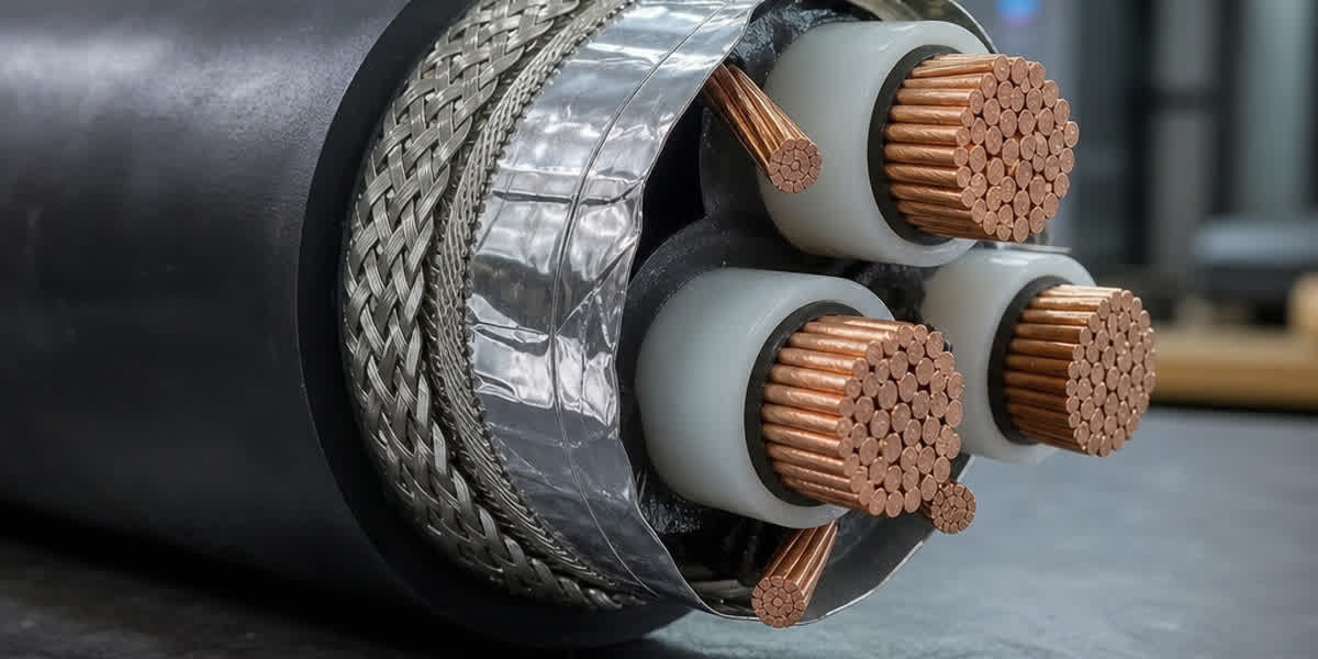
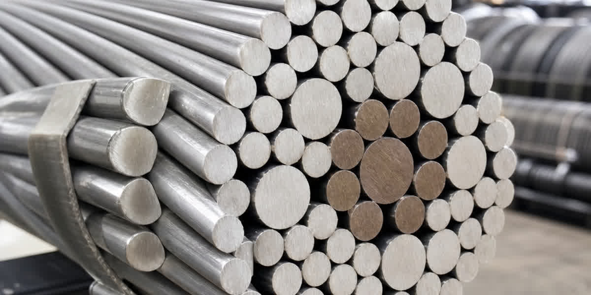
El conductor STACIR/AW adopta una estructura cableada de capas concéntricas compuesta por un núcleo de aleación Invar (hierro-níquel, Fe-Ni, con aproximadamente un 36 % de níquel) y una capa exterior de alambres de aleación de aluminio supertermorresistente (Super Thermal-resistant Aluminum, con una conductividad del 58 %–60 % IACS). La singularidad del Invar reside en su coeficiente de expansión térmica extremadamente bajo (aproximadamente 1,2 × 10⁻⁶ /°C), muy inferior al del acero común (aproximadamente 11,5 × 10⁻⁶ /°C), lo que permite que el conductor STACIR/AW presente incrementos mínimos de flecha durante la operación a alta temperatura.
Tabla de Especificaciones Técnicas
A continuación se presentan los parámetros técnicos de los modelos más comunes de conductores STACIR/AW, que abarcan desde aplicaciones de distribución ligera hasta líneas troncales de transmisión de alta capacidad:
| Código | Sección (mm²) | Cableado (Al/Invar) | Diámetro exterior (mm) | RTS (kN) | Peso (kg/km) | Resistencia CC 20 °C (Ω/km) | Capacidad 150 °C (A) | Capacidad 210 °C (A) |
|---|---|---|---|---|---|---|---|---|
| STACIR/AW 100 | 100 | 12/7 | 13,5 | 42,5 | 399 | 0,2815 | 345 | 410 |
| STACIR/AW 150 | 150 | 18/7 | 16,5 | 58,8 | 576 | 0,1877 | 450 | 535 |
| STACIR/AW 200 | 200 | 24/7 | 19,1 | 76,5 | 754 | 0,1408 | 540 | 640 |
| STACIR/AW 240 | 240 | 26/7 | 20,9 | 88,2 | 895 | 0,1173 | 610 | 725 |
| STACIR/AW 300 | 300 | 30/7 | 23,4 | 105,9 | 1105 | 0,0939 | 700 | 830 |
| STACIR/AW 330 | 330 | 42/7 | 24,6 | 115,6 | 1218 | 0,0853 | 745 | 885 |
| STACIR/AW 400 | 400 | 42/7 | 27,1 | 134,3 | 1456 | 0,0704 | 840 | 1000 |
| STACIR/AW 500 | 500 | 54/7 | 30,3 | 162,8 | 1816 | 0,0563 | 960 | 1145 |
| STACIR/AW 600 | 600 | 54/7 | 33,2 | 189,2 | 2155 | 0,0469 | 1080 | 1285 |
| STACIR/AW 720 | 720 | 54/19 | 36,3 | 226,4 | 2610 | 0,0391 | 1205 | 1440 |
Notas:
- Los valores de capacidad de corriente se basan en las siguientes condiciones de referencia: temperatura ambiente de 40 °C, velocidad del viento de 0,5 m/s, radiación solar de 1000 W/m², coeficiente de absorción solar de 0,5 y coeficiente de emisividad superficial de 0,5.
- La capacidad de corriente real debe corregirse según los parámetros ambientales específicos de cada proyecto (altitud, velocidad del viento real, condiciones de radiación solar, etc.), siguiendo preferiblemente la norma IEEE 738.
- La notación de cableado (por ejemplo, «30/7») indica el número de alambres de aluminio (30) y el número de alambres del núcleo de Invar (7).
- Se pueden fabricar secciones no estándar y estructuras especiales según los requisitos del cliente.
Recomendaciones de selección: Para líneas de distribución de 69 kV o inferiores, se recomiendan los modelos STACIR/AW 100 a 240. Para líneas de transmisión de 110 kV a 138 kV, se recomiendan los modelos STACIR/AW 240 a 400. Para líneas troncales de alta tensión de 230 kV o superiores, se recomiendan los modelos STACIR/AW 400 a 720.
Tabla Comparativa: STACIR/AW vs Otros Conductores
| Parámetro | STACIR/AW (aluminio supertermorresistente con Invar) | ACSR (aluminio con núcleo de acero) | ACSS (aluminio recocido con núcleo de acero) | AAAC (aleación de aluminio) |
|---|---|---|---|---|
| Temperatura máxima de operación | 150 °C – 210 °C | 75 °C – 90 °C | 200 °C – 250 °C | 75 °C – 90 °C |
| Comportamiento de flecha a alta temperatura | Excelente (coeficiente de expansión térmica del Invar extremadamente bajo) | Deficiente (gran incremento de flecha a alta temperatura) | Bueno (el aluminio recocido se relaja plásticamente reduciendo la flecha) | Deficiente (gran incremento de flecha a alta temperatura) |
| Resistencia mecánica (RTS) | Alta | Alta | Media | Media |
| Fluencia a alta temperatura | Excelente | Deficiente (los alambres de aluminio se endurecen y fragilizan) | Excelente (el aluminio ya está prerrecocido) | Regular |
| Resistencia a la corrosión | Excelente (la aleación Invar ofrece buena resistencia a la corrosión) | Regular (el núcleo de acero requiere protección galvanizada) | Regular (el núcleo de acero requiere protección galvanizada o aluminizada) | Excelente (sin núcleo de acero, completamente de aleación de aluminio) |
| Conductividad (% IACS) | 58 % – 60 % | 61 % (solo los alambres de aluminio) | 61 % – 63 % (aluminio recocido) | 52 % – 53 % |
| Índice de coste (respecto al ACSR) | 2,5 – 3,5 veces | 1,0 (referencia) | 1,5 – 2,0 veces | 1,2 – 1,5 veces |
| Aplicación típica | Reconductorización, tramos con restricciones de corredor | Transmisión convencional, líneas nuevas | Grandes vanos, reconductorización a alta temperatura | Líneas en entornos costeros o corrosivos |
| Complejidad de herrajes | Media (requiere herrajes resistentes a alta temperatura) | Baja | Media (requiere herrajes resistentes a alta temperatura) | Baja |
Análisis: El STACIR/AW ofrece una ventaja insustituible en el control de la flecha a alta temperatura: el coeficiente de expansión térmica del núcleo de Invar es apenas una décima parte del del acero común. Esto significa que, en condiciones de operación entre 150 °C y 210 °C, el incremento de flecha del STACIR/AW es solo del 30 % al 40 % del que experimentaría un conductor ACSR en las mismas condiciones. Cuando se requiere combinar capacidad de ampliación con restricciones severas de flecha, el STACIR/AW suele ser la opción preferente.
Escenarios de Aplicación
| Escenario de aplicación | Desafío técnico | Solución HTLS recomendada | Beneficio esperado |
|---|---|---|---|
| Reconductorización (69 kV → 138 kV) | Las torres existentes no cumplen los requisitos de carga y flecha para la nueva tensión | Sustituir el ACSR original por STACIR/AW | Aumento del nivel de tensión; capacidad de transmisión 2–3 veces superior |
| Reconductorización (138 kV → 230 kV) | Las cimentaciones de las torres existentes no soportan conductores más pesados | Utilizar STACIR/AW manteniendo o reduciendo el peso propio y aumentando la sección conductora | Capacidad de transmisión 1,5–2 veces superior |
| Descongestión de líneas (misma tensión) | El conductor actual ha alcanzado su límite térmico sin posibilidad de nuevo corredor | Reemplazar por STACIR/AW manteniendo un diámetro exterior similar | Capacidad de transmisión 50 % – 100 % superior |
| Tramo con corredor restringido | No es posible ampliar el corredor ni elevar las torres | La baja flecha del STACIR/AW evita conflictos con obstáculos inferiores | Reconductorización sin modificar las torres existentes |
| Renovación de líneas antiguas | Conductores con más de 30 años en servicio, fatiga de aluminio pero cimentaciones en buen estado | Reemplazar por STACIR/AW aumentando simultáneamente la capacidad | Extensión de la vida útil 15–20 años con aumento de capacidad |
| Nuevas líneas en corredores verdes | Restricciones ambientales limitan la altura de torres y la anchura del corredor | Emplear STACIR/AW de gran sección para reducir la anchura del corredor | Reducción del 30 % – 40 % en la superficie de expropiación; menor presión ambiental |
| Grandes vanos (cruces de ríos, valles) | Vanos largos requieren un control estricto de la flecha | STACIR/AW con herrajes reforzados | Distancias de seguridad al suelo en condiciones de gran vano |
Metodología de Selección (Cinco Pasos)
Paso 1: Determinar la capacidad objetivo
A partir de la planificación del sistema, establecer la capacidad de corriente objetivo (A) y el nivel de tensión de operación después de la ampliación. Estos datos determinan la sección conductora y el grado de resistencia térmica requeridos.
Paso 2: Evaluar las restricciones de flecha
Recopilar la distribución de vanos, la altura de las torres, las distancias al suelo y las limitaciones de cruzamientos de la línea existente. La restricción de flecha es a menudo el factor decisivo en la selección: si no es posible elevar las torres existentes, es obligatorio elegir un conductor HTLS con bajo coeficiente de expansión térmica, como el STACIR/AW.
Paso 3: Seleccionar la especificación del conductor
Bajo el doble requisito de la capacidad de corriente objetivo y las restricciones de flecha, consultar la tabla de especificaciones técnicas del STACIR/AW para preseleccionar los modelos que cumplen con la capacidad requerida y verificar que la flecha a la temperatura de operación objetivo respeta las distancias de seguridad al suelo.
Paso 4: Verificar las cargas sobre la torre
Calcular las cargas mecánicas del conductor candidato (peso propio, carga de hielo, carga de viento y tensión) y compararlas con la capacidad de carga de diseño de las torres existentes. El STACIR/AW suele tener un peso similar o ligeramente inferior al del ACSR original, lo que favorece la reducción de las modificaciones estructurales necesarias en las torres.
Paso 5: Evaluación económica
Realizar un análisis integral que incluya el coste de adquisición del conductor, los costes de los herrajes, los gastos de instalación y los beneficios operativos durante el ciclo de vida de la línea. Aunque la inversión inicial en conductores HTLS es más elevada, si se evita la necesidad de modificar torres o construir nuevos corredores, la relación coste-beneficio suele ser favorable en comparación con las soluciones tradicionales.
Consideraciones de Instalación
Límites de Tensión de Tendido
El núcleo de aleación Invar del conductor STACIR/AW presenta un módulo de elasticidad relativamente alto (aproximadamente 140–150 GPa), y los alambres de aluminio son de aleación supertermorresistente. Durante el tendido, la tensión de tendido no debe superar el 20 %–25 % de la resistencia nominal a la tracción (RTS) del conductor. El diámetro de las poleas de tendido no debe ser inferior a 30 veces el diámetro exterior del conductor para evitar daños por flexión en los alambres de aluminio.
Requisitos de Herrajes
Dado que el conductor STACIR/AW opera de forma continua a temperaturas entre 150 °C y 210 °C, los herrajes utilizados deben cumplir los siguientes requisitos:
- Grapas de anclaje: Deben ser del tipo de compresión, fabricadas en aleación de aluminio termorresistente o acero inoxidable, y deben superar ensayos de ciclos térmicos que validen su funcionamiento a la temperatura de operación.
- Manguitos de empalme: Deben tener una capacidad de resistencia térmica equivalente a la del conductor (aleación de aluminio termorresistente). Después del crimpado, deben garantizar una retención del 100 % de la RTS.
- Grapas de suspensión: Se recomienda el uso de grapas de suspensión preformadas. Las almohadillas de goma deben ser resistentes a temperaturas superiores a 200 °C.
- Amortiguadores de vibración: Dado que el núcleo de Invar presenta características de vibración diferentes a las del acero, la posición y la frecuencia de los amortiguadores deben diseñarse específicamente.
Medidas Antivibración
El núcleo de Invar del STACIR/AW tiene un módulo elástico elevado y una gran rigidez, por lo que su respuesta en frecuencia a las vibraciones eólicas difiere de la de los conductores ACSR convencionales. Se recomienda el siguiente plan antivibración:
- Realizar una evaluación específica de las vibraciones de subvano y las vibraciones eólicas.
- Emplear una combinación de varillas preformadas de protección y amortiguadores antivibración.
- En tramos de gran vano, instalar amortiguadores espirales o cables amortiguadores adicionales.
- Verificar rigurosamente la posición de los amortiguadores antivibración, asegurando que se encuentren cerca de los nodos de la onda estacionaria.
Ambiente y Durabilidad
Evaluación de la adaptabilidad del conductor STACIR/AW en diferentes condiciones ambientales:
| Condición ambiental | Riesgo potencial | Comportamiento del STACIR/AW | Recomendación de protección |
|---|---|---|---|
| Corrosión por niebla salina costera | Corrosión por cloruros en alambres de aluminio y herrajes | Excelente — La aleación Invar ofrece una resistencia a la corrosión por cloruros superior a la del núcleo de acero galvanizado | Relleno de los alambres de aluminio con grasa anticorrosiva; herrajes galvanizados en caliente o de acero inoxidable |
| Contaminación industrial (lluvia ácida, sulfuros) | Picaduras superficiales en el aluminio, corrosión bajo tensión del núcleo | Buena — La aleación de aluminio supertermorresistente tiene una resistencia a la corrosión similar a la del aluminio común | Limpieza periódica (cada 2–3 años); aplicación de revestimiento anticorrosivo si es necesario |
| Zonas de hielo / hielo pesado | Sobrecarga mecánica, impacto por desprendimiento no uniforme del hielo | Excelente — La aleación Invar ofrece alta resistencia mecánica y buena tenacidad a baja temperatura | Instalación de sistemas de monitorización de hielo; establecer valores adecuados de corriente de deshielo |
| Radiación ultravioleta (UV) | Engrosamiento de la capa de óxido en la superficie del aluminio | Excelente — El aluminio se autopasiva formando una película protectora de óxido de aluminio | No se requieren medidas especiales de protección UV |
| Envejecimiento por alta temperatura (150 °C+ prolongado) | Recocido y ablandamiento del aluminio, degradación del núcleo | Excelente — Diseñado específicamente para alta temperatura; vida útil superior a 30 años a 150 °C | Controlar la temperatura de sobrecarga de corta duración por debajo de 230 °C para evitar el recocido excesivo del aluminio |
Caso de Estudio: Reconductorización de una Línea de 138 kV
Antecedentes del proyecto: Una línea de transmisión de 138 kV con 20 años de servicio, de aproximadamente 50 km de longitud, equipada con conductor ACSR Drake (sección de aproximadamente 402 mm², núcleo de acero con cableado 26/7). Debido al rápido crecimiento de la demanda en la región, la línea había alcanzado el límite superior de su capacidad térmica y era necesario incrementar la capacidad de transmisión a 1,8 veces el valor original.
Condiciones restrictivas:
- Las cimentaciones de las torres no podían ser elevadas ni reconstruidas.
- El corredor de la línea estaba rodeado de zonas urbanizadas, imposibilitando su ampliación.
- El incremento máximo admisible de flecha no debía superar 1,2 m.
Selección de la solución
Tras los cálculos correspondientes, se determinó que, manteniendo la altura de las torres existentes y respetando las restricciones de flecha, la capacidad de corriente del ACSR Drake a 90 °C era insuficiente para alcanzar el objetivo. Después de evaluar múltiples alternativas, se seleccionó el conductor STACIR/AW 400 (estructura 42/7, sección de aproximadamente 400 mm²) como conductor de sustitución.
Plan de reconductorización
| Parámetro | Antes de la reconductorización (ACSR Drake) | Después de la reconductorización (STACIR/AW 400) |
|---|---|---|
| Tipo de conductor | ACSR Drake 402 mm² | STACIR/AW 400 (42/7) |
| Sección | 402 mm² | 400 mm² |
| Diámetro exterior | 28,1 mm | 27,1 mm |
| Peso | 1605 kg/km | 1456 kg/km |
| Resistencia nominal a la tracción (RTS) | 127,0 kN | 134,3 kN |
| Temperatura máxima de operación | 90 °C | 150 °C (puntual 210 °C) |
| Capacidad de corriente (condiciones de referencia) | 720 A (90 °C) | 840 A (150 °C) / 1000 A (210 °C) |
| Flecha a 40 °C (referencia) | 7,5 m | 7,3 m |
| Flecha a la temperatura objetivo | 10,8 m (90 °C) | 8,5 m (150 °C) |
| Incremento de capacidad de transmisión | — | +60 % (operación a 150 °C) |
Resultados de la implementación:
- La capacidad de transmisión aumentó de aproximadamente 170 MVA a aproximadamente 270 MVA (operación a 150 °C), un incremento de aproximadamente el 60 %.
- No fue necesario reemplazar ni reforzar las torres existentes; solo se sustituyeron los herrajes correspondientes.
- El incremento de flecha se mantuvo dentro del límite de 1,2 m, cumpliendo todos los requisitos de seguridad.
- El período de construcción fue de aproximadamente 3 meses, lo que supuso un ahorro de aproximadamente el 70 % del tiempo y el 85 % de la inversión en comparación con la construcción de una nueva línea.
- Desde su puesta en servicio, la línea ha operado de forma estable, sin alertas de flecha durante las temporadas de alta temperatura.
Preguntas Frecuentes (FAQ)
P1: ¿Qué es la aleación Invar en el conductor STACIR/AW?
El Invar es una aleación de hierro y níquel, con un contenido de níquel de aproximadamente el 36 %, conocida por su coeficiente de expansión térmica extremadamente bajo (aproximadamente 1,2 × 10⁻⁶ /°C). El nombre «Invar» proviene de «Invariable» (invariable). En los conductores HTLS, el Invar se utiliza como material del núcleo, lo que permite que el conductor mantenga variaciones mínimas de flecha incluso a altas temperaturas.
P2: ¿Cuál es la diferencia entre STACIR/AW y ACSS? ¿Cuál es mejor?
Ambos son conductores HTLS maduros, pero sus principios son diferentes. El STACIR/AW controla la flecha mediante el bajo coeficiente de expansión térmica del Invar. El ACSS utiliza alambres de aluminio totalmente recocido que experimentan relajación plástica a alta temperatura, compensando automáticamente la flecha bajo tensión inicial. La elección depende de las condiciones del proyecto: si las restricciones de flecha son muy estrictas, el STACIR/AW ofrece un mejor rendimiento; si se requiere una conductividad ligeramente superior, el ACSS (con un 63 % IACS) puede ser ventajoso.
P3: ¿Cuál es el rango de temperatura de operación del conductor STACIR/AW?
La temperatura de operación continua es de 150 °C, y la sobrecarga de emergencia de corta duración puede alcanzar los 210 °C. En condiciones de emergencia (por ejemplo, cuando una línea adyacente sale de servicio), se permite la operación a 210 °C durante un máximo de 2 horas. Se recomienda mantener la temperatura de operación diaria por debajo de 150 °C para prolongar la vida útil del conductor.
P4: ¿Se puede reemplazar directamente un conductor ACSR por STACIR/AW en las torres existentes?
En la gran mayoría de los casos sí —esta es una de las ventajas principales del STACIR/AW. El peso del STACIR/AW suele ser similar o ligeramente inferior al del ACSR original, el diámetro exterior es comparable y la resistencia mecánica cumple con los requisitos. Sin embargo, antes de la sustitución es necesario verificar las cargas sobre las torres existentes, especialmente en las cadenas de suspensión y anclaje.
P5: ¿Se necesitan herrajes especiales para las conexiones del conductor STACIR/AW?
Sí. Los herrajes estándar para ACSR tienen una temperatura nominal que generalmente no supera los 120 °C, insuficiente para los 150 °C–210 °C de operación del STACIR/AW. Es obligatorio utilizar herrajes especiales fabricados en aleación de aluminio termorresistente o acero inoxidable, con una temperatura nominal no inferior a la temperatura máxima de operación del conductor.
P6: ¿Cuál es la vida útil del conductor STACIR/AW?
En condiciones normales de operación (temperatura de funcionamiento no superior a 150 °C), la vida útil de diseño del conductor STACIR/AW es de 30 a 40 años, comparable a la del ACSR. Dado que el núcleo de Invar no contiene acero galvanizado susceptible a la corrosión, su durabilidad es incluso superior a la del ACSR tradicional.
P7: ¿Cuánto más caro es el STACIR/AW en comparación con el ACSR?
Debido al mayor coste de las materias primas (aleación Invar y aluminio supertermorresistente) y a la mayor complejidad del proceso de fabricación, el precio inicial del STACIR/AW es de 2,5 a 3,5 veces el del ACSR de la misma especificación. Sin embargo, considerando el ahorro al no tener que reemplazar torres ni construir nuevos corredores, el coste total del proyecto suele ser solo un 20 %–40 % superior al de una reconductorización con ACSR, y muy inferior al coste de una línea nueva.
P8: ¿Cómo se calcula la capacidad de corriente real del conductor STACIR/AW?
Se recomienda seguir la norma IEEE 738 para el cálculo de la capacidad de corriente, considerando factores como la temperatura ambiente, la velocidad del viento, la radiación solar, la altitud y la emisividad superficial del conductor. El equipo técnico de SiTong Cable ofrece servicios de cálculo de capacidad de corriente adaptados a las condiciones específicas de cada proyecto. No dude en contactar a nuestro equipo técnico para obtener asistencia.
Conclusión
El conductor STACIR/AW (aluminio supertermorresistente reforzado con Invar), como producto central de la familia de conductores HTLS, ofrece una solución eficiente y probada para la reconductorización de líneas de transmisión gracias a sus ventajas técnicas distintivas: el coeficiente de expansión térmica extremadamente bajo del núcleo de Invar y la estabilidad a alta temperatura de los alambres de aleación de aluminio supertermorresistente.
Para aquellos proyectos de ingeniería eléctrica que enfrentan desafíos típicos como la sobrecarga de líneas, las restricciones de corredor o la imposibilidad de modificar las torres existentes, el STACIR/AW permite incrementar la capacidad de transmisión entre un 50 % y un 100 % sin necesidad de reemplazar las torres, manteniendo la flecha a alta temperatura dentro de los límites de seguridad. Tanto en la actualización de tensión de líneas de distribución de 69 kV como en la ampliación de capacidad de líneas troncales de transmisión de 230 kV, el STACIR/AW demuestra una adaptabilidad técnica excepcional.
La selección del conductor adecuado es el primer paso crítico para el éxito de un proyecto de reconductorización. SiTong Cable ofrece una gama completa de conductores aéreos, incluyendo:
- Explore nuestros conductores ACSR — ideales para proyectos de transmisión convencional
- Explore nuestros conductores AAAC — recomendados para entornos corrosivos
- Explore nuestros conductores AAC — adecuados para líneas de distribución
Si necesita asesoramiento en la selección de conductores STACIR/AW para su proyecto específico, cálculo de capacidad de corriente o consultoría técnica, no dude en contactar a nuestro equipo técnico para recibir asistencia profesional.