Control Cable (Instrumentation & Control Cable): Complete Technical Guide — Standards, Specifications, Construction & Selection for Industrial Applications

2026-07-17 | SiTong Cable | technical
Control Cable (Instrumentation & Control Cable): Complete Technical Guide — Standards, Specifications, Construction & Selection for Industrial Applications

Control Cable (Instrumentation & Control Cable): Complete Technical Guide — Standards, Specifications, Construction & Selection for Industrial Applications

Control cables, also known as instrumentation and control cables, are the backbone of industrial automation, power distribution systems, and process control networks. Unlike standard power cables which transmit bulk electrical energy, control cables are designed to carry low-voltage signals, control commands, and instrumentation data between control equipment, sensors, actuators, and monitoring devices. This comprehensive guide covers everything you need to know about control cable construction, international standards, specification parameters, selection criteria, and installation best practices for industrial applications.

What is a Control Cable? Definition and Core Function

A control cable is a multiconductor cable specifically designed for the transmission of control signals, instrumentation data, and low-voltage power in industrial environments. Control cables differ from power cables in several critical aspects: they typically operate at lower voltages (generally below 1000 V), carry signals rather than substantial current, require enhanced electromagnetic shielding to prevent interference, and must maintain signal integrity over long distances in electrically noisy environments.

The primary function of control cables is to connect control panels, programmable logic controllers (PLCs), distributed control systems (DCS), variable frequency drives (VFDs), sensors, transmitters, actuators, and other field devices in industrial control loops. They are essential components in virtually every industrial sector, including oil and gas refining, chemical processing, power generation, water treatment, mining, cement production, and manufacturing automation.

Control Cable Construction: Key Components and Their Roles

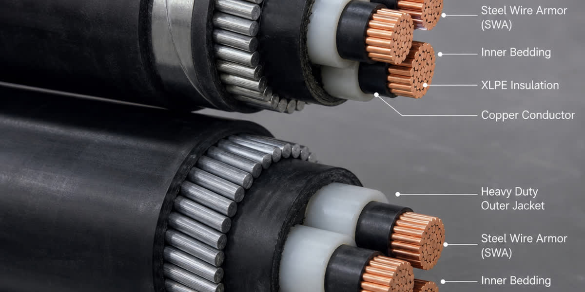
Understanding the construction of a control cable is essential for proper specification. Each layer serves a specific function in protecting signal integrity and ensuring long-term reliability.

1. Conductor Material and Stranding

Control cable conductors are typically made of annealed copper (plain or tinned), with tinned copper offering superior corrosion resistance in humid or chemical environments. Conductors are stranded rather than solid to provide flexibility during installation and to withstand vibration in industrial applications.

The most common stranding classes for control cables: - Class 2: Standard stranded — suitable for fixed installations in trays and conduits - Class 5: Fine stranded — offers higher flexibility for applications requiring frequent flexing or tight bending radii - Class 6: Extra-fine stranded — used in dynamic applications like robotic cable management systems

Conductor sizes commonly range from 0.5 mm² (20 AWG) for instrumentation signals up to 10 mm² (7 AWG) or larger for combined power/control applications.

2. Insulation Materials

The insulation material determines the cable's voltage rating, temperature range, and chemical resistance. The most common insulation materials for control cables include:

  • PVC (Polyvinyl Chloride): Economical and widely used for general-purpose control applications up to 90°C. Suitable for dry and lightly damp environments.
  • XLPE (Cross-Linked Polyethylene): Superior thermal performance up to 105°C (emergency rating 130°C), higher current-carrying capacity, and excellent dielectric properties. Preferred for high-temperature and high-reliability applications.
  • PE (Polyethylene): Excellent electrical insulation properties and low dielectric constant, ideal for high-frequency signal transmission.
  • LSZH (Low Smoke Zero Halogen): Mandatory for public buildings, tunnels, railways, and offshore installations where fire safety is critical. Produces minimal smoke and no toxic halogen gases when burned.
  • EPR (Ethylene Propylene Rubber): Outstanding flexibility, excellent wet electrical properties, and wide temperature range. Ideal for installations in damp or wet conditions.

3. Color Coding and Core Identification

International standards dictate color coding for control cable cores: - IEC 60227 / HD 308: Uses green-yellow for protective earth, with numbered or colored cores for phase and neutral identification - NEC (North America): Uses specific color sequences based on voltage class and circuit type - EN 50288: Specifies color coding for multicore instrumentation and control cables

Numbered cores (with printed numbers on the insulation) are increasingly preferred for complex installations with many conductors, as they simplify termination and troubleshooting.

4. Shielding and Screening

Shielding is the most critical feature distinguishing control cables from plain power cables. Proper shielding prevents electromagnetic interference (EMI) and radio-frequency interference (RFI) from corrupting low-voltage control signals.

Common shielding configurations:

Shielding Type Description Typical Application
Overall foil shield Aluminum/polyester tape with drain wire General-purpose control, moderate EMI protection
Overall braid shield Tinned copper braid (typically 65-90% coverage) High EMI environments, flexible applications
Individual pair/triad shields Each pair or triad individually foil-shielded Instrumentation signals, sensitive analog signals
Combined foil + braid Foil shield plus braid for maximum protection Critical instrumentation, VFD motor cables
Armor shield Steel wire or steel tape over the assembled cores Mechanical protection in direct-burial or heavy industrial areas

5. Inner Sheath and Outer Jacket

The inner sheath (interlayer) provides mechanical bedding and may provide additional insulation. The outer jacket protects the cable against installation and environmental stresses. Common jacket materials include: - PVC (Type ST1/ST2): General purpose indoor - PE (Polyethylene): Superior moisture resistance for outdoor/underground - PUR (Polyurethane): Exceptional abrasion and cut resistance for harsh environments - LSZH: Fire-safe for public and high-occupancy areas - CPE (Chlorinated Polyethylene): Excellent oil and chemical resistance

International Standards for Control Cables

Control cables are manufactured and tested according to stringent international standards to ensure consistent performance and safety.

IEC Standards

  • IEC 60092-375: Control cables for ships and offshore units
  • IEC 60227 (series): Polyvinyl chloride insulated cables of rated voltages up to 450/750 V
  • IEC 60502-1: Power cables with extruded insulation rated up to 3.6/6 kV (covers many control cable types)
  • IEC 60332-1 / 60332-3: Flame retardant and flame propagation tests
  • IEC 60754-1 / 60754-2: Halogen gas evolution and acidity testing
  • IEC 61034: Smoke density measurement during combustion
  • IEC 60811: Generic test methods for insulation and sheathing materials
  • EN 50288: Multicore metallic cables for analog and digital signals (European standard)

IEEE/NEC Standards

  • IEEE 383: Type test for power, control, and instrumentation cables for nuclear power plants
  • IEEE 1202: Flame propagation testing for cables in cable trays
  • UL 1277: Type MC power and control cables (North America)
  • UL 13: Power-limited circuit cables
  • NEC Article 725: Class 1, Class 2, and Class 3 remote control circuits

British Standards

  • BS 5308: Instrumentation cables (Part 1: PVC insulated, Part 2: PE insulated)
  • BS 6346: PVC insulated power cables including control cable types
  • BS 7655: Specification for insulating and sheathing compounds

Types of Control Cables by Application

1. Instrumentation Cables (BS 5308 / EN 50288)

Designed specifically for transmitting low-level analog signals (4-20 mA, thermocouple, RTD, millivolt) from field instruments to control systems. These cables feature individually shielded pairs/triads with overall shielding for maximum signal integrity. They are color-coded according to instrument loop standards and typically Class 2 or Class 5 stranded conductors.

2. PVC Control Cables (IEC 60227-5 / BS 6346)

The most widely used control cable type for general industrial applications. Suitable for fixed installations in dry or damp locations, cable trays, conduits, and duct banks. PVC offers good electrical properties, adequate chemical resistance, and the most economical cost.

3. XLPE Insulated Control Cables (IEC 60502-1)

Preferred for higher temperature environments and higher reliability requirements. XLPE insulation allows higher current ratings than PVC for the same conductor size. Widely specified in power plants, substations, and heavy industrial facilities.

4. Armored Control Cables (SWA / AWA / SWB)

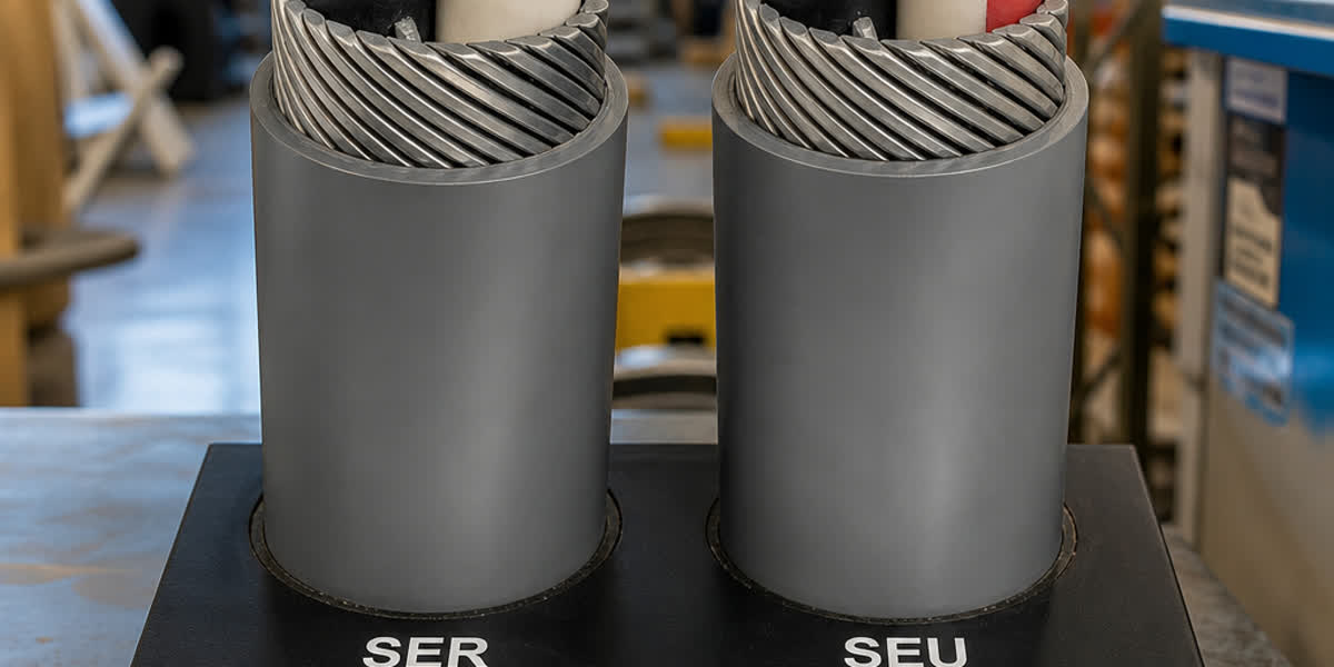
Steel wire armored (SWA) control cables provide mechanical protection for direct burial, outdoor installations, and heavy industrial environments where physical damage is a risk. Aluminum wire armor (AWA) offers protection with lighter weight. Steel tape or steel wire braid (SWB) provides varying levels of mechanical protection.

5. Fire-Resistant Control Cables (BS 7629 / IEC 60331)

Designed to maintain circuit integrity during a fire. These cables use fire-resistant insulation such as mica tape plus XLPE to continue functioning for a defined period (typically 30-90 minutes) during fire conditions. Essential for emergency systems, fire alarms, sprinkler control, and emergency lighting.

6. Marine and Offshore Control Cables (IEC 60092)

Specially constructed to resist saltwater corrosion, vibration, and the harsh conditions of marine environments. Features tinned copper conductors, enhanced sheathing, and compliance with marine classification society requirements (Lloyd's, DNV, ABS).

7. Oil and Chemical Resistant Control Cables

For installations in petrochemical plants, refineries, and chemical processing facilities. These cables use oil-resistant jacket compounds (CPE, PUR, or specialty PVC) and may feature additional barrier layers to prevent chemical permeation.

How to Select the Right Control Cable for Your Application

Selecting the correct control cable requires a systematic evaluation of operating conditions and performance requirements:

Step 1: Determine Voltage Rating

Control cables are typically rated 300/500 V or 450/750 V. For instrumentation circuits, 300/500 V is generally sufficient. For combined power and control circuits (common in VFD installations), 450/750 V or higher may be required.

Step 2: Count Conductors and Configure Core Layout

Identify the number of signal circuits, power feeds, and spare cores. Common configurations include: - Multicore: 2, 3, 4, 5, 7, 12, 19, 24, 37, or 48 cores - Paired: 1, 2, 4, 8, 12, 16, 24 pairs - Triads: 3-core groups for three-phase instrument power

Always include 15-20% spare cores for future expansion and troubleshooting.

Step 3: Match Shielding to Signal Sensitivity

Signal Type Recommended Shielding
Digital signals (relay, contact closure) Overall foil shield
4-20 mA analog signals Individual pair shield + overall shield
Thermocouple / RTD Individual pair shield (twisted pairs)
VFD motor cables Symmetrical construction + copper braid + armor
RS-485 / Modbus communication Overall braid shield (≥85% coverage)
Ethernet / fieldbus Pair-shielded + overall braid

Step 4: Evaluate Environmental Conditions

Consider installation environment factors: - Temperature range: Ambient temperature + temperature rise from adjacent cables - Moisture exposure: Dry indoor vs. damp vs. wet vs. direct burial - Chemical exposure: Oils, solvents, acids, or corrosive gases present - UV exposure: Outdoor sunlight exposure requires UV-stabilized jacket - Mechanical stress: Flexing, vibration, crushing, or impact risks - Fire safety requirements: LSZH mandated for public buildings and tunnels

Step 5: Verify Compliance and Certification

Ensure the selected cable meets all applicable standards and regulatory requirements for your jurisdiction and industry sector.

Control Cable Installation Best Practices

Proper installation is critical for control cable performance and longevity. The following practices will maximize signal integrity and service life:

Separation from Power Cables

Control cables, especially unshielded types, must be physically separated from power cables to prevent inductive and capacitive coupling. Recommended minimum separation distances per IEC 60364 and other standards:

Power Cable Voltage Parallel Run Separation Crossing Separation
< 1 kV 100-150 mm 50 mm
1-10 kV 200-300 mm 50 mm
> 10 kV 400-600 mm 100 mm

Install steel barriers between control and power cable trays for additional isolation where separation distances cannot be maintained.

Minimum Bending Radius

Control cables must not be bent tighter than the specified minimum bending radius (MBR). Standard MBR values: - Unarmored cables: 6-8× cable overall diameter - Armored cables: 10-12× cable overall diameter - Flexible cables: 4-5× cable overall diameter

Cable Glanding and Termination

Proper glanding ensures mechanical retention, earth continuity (through armor/braid), and environmental sealing. Pigtail drain wires should be connected to the control panel earth bus using the shortest possible route. Shielding should typically be grounded at one end only (usually the controller end) to avoid ground loops, except for RF/VFD cables where both ends may be grounded.

Cable Support and Fixing

Support cables in vertical runs at intervals not exceeding: - Unarmored: 200-300 mm - Lightly armored: 300-450 mm - Heavily armored: 400-600 mm

For horizontal cable trays, follow manufacturer loading specifications (typically 60% fill maximum) and use proper separators between control and power cables.

Comparison: Control Cable vs. Power Cable vs. Instrumentation Cable

Property Power Cable Control Cable Instrumentation Cable
Primary function Transmit bulk electrical power Transmit control signals and power Transmit low-level sensor signals
Voltage rating 0.6/1 kV to 33 kV+ 300/500 V to 0.6/1 kV 300/500 V max
Conductor size 16-630 mm² typical 0.5-10 mm² typical 0.5-2.5 mm² typical
Core count 1-5 cores typical 2-48+ cores 2-48+ pairs
Shielding Optional (MV cables) Standard Mandatory, each pair
Key standard IEC 60502, IEC 60840 IEC 60227, EN 50288 BS 5308, EN 50288
Application Distribution, feeders PLC, DCS, SCADA control 4-20 mA, RTD, thermocouple

Frequently Asked Questions

Q1: What is the difference between a control cable and an instrumentation cable?

Control cables are designed to carry control signals and low-voltage power to actuators, motors, and equipment, typically featuring overall shielding. Instrumentation cables are a specialized subset designed for low-level analog signals (4-20 mA, thermocouple, RTD), and always feature individual pair or triad shielding to preserve signal integrity in the millivolt range. Instrumentation cables are typically specified to BS 5308 or EN 50288 standards.

Q2: Can I use a power cable for control applications?

While power cables can carry electricity, they lack the shielding, core count, and stranding characteristics needed for reliable control signal transmission. Without proper shielding, control signals are highly susceptible to electromagnetic interference from nearby power conductors, leading to spurious signals, equipment misoperation, and data corruption. Always use cables specifically designed and rated for control applications.

Q3: What does "LSZH" mean on a control cable specification?

LSZH stands for Low Smoke Zero Halogen. LSZH cables are manufactured using materials that produce minimal smoke (by IEC 61034) and emit no toxic or corrosive halogen gases (by IEC 60754) when exposed to fire. LSZH control cables are mandatory in public buildings, airports, railway stations, tunnels, hospitals, and offshore installations where smoke inhalation and equipment corrosion from halogen gases pose serious safety risks.

Q4: How should I connect the shield drain wire for control cables?

For most analog signal applications, the shield drain wire should be grounded at the controller/receiver end only. Grounding at both ends creates ground loops that induce 50/60 Hz hum on the signal. Exceptions include VFD motor cables (both ends grounded for RFI suppression) and high-frequency communication cables. The drain wire connection should be as short as possible — ideally less than 50 mm from the cable entry to the earth bus.

Q5: What is the standard color code for control cables in Europe?

Per HD 308 (harmonization document) adopted across European countries: green-yellow for protective earth (PE), light blue for neutral, brown-black-grey for 3-phase conductors, and numbered cores beginning from the first numbered core for control circuits. For instrumentation cables per EN 50288, individual pair identification uses specific color pairs (e.g., blue/blue-white, orange/orange-white) to enable rapid identification during termination.

Conclusion

Control cables are a critical infrastructure component for every industrial facility. Selecting the correct cable type, shielding configuration, insulation material, and construction features directly impacts system reliability, signal integrity, and long-term operating costs. By understanding the standards (IEC 60227, IEC 60502, BS 5308, EN 50288, UL 1277), matching cable construction to the application environment, and observing proper installation practices, engineers and specifiers can ensure that their control systems operate reliably for decades. For customized control cable solutions, explore SiTong Cable's control cable product range or complement your installation with SiTong's power cables for comprehensive facility wiring.