OPGW Construction & Hardware: Fiber Units and Accessories

OPGW Construction & Hardware: Fiber Units and Accessories
Introduction
OPGW (Optical Ground Wire) represents one of the most significant innovations in overhead transmission line technology over the past three decades. Installed at the top of transmission towers — replacing traditional steel ground wires — OPGW serves a dual purpose: it protects phase conductors from direct lightning strikes while simultaneously providing a high-capacity optical fiber communication channel for grid monitoring, protection signaling, SCADA and broadband telecommunications.
Since its commercial introduction in the 1980s, OPGW has become the standard fiber optic solution for high-voltage transmission lines worldwide. According to industry estimates, over 500,000 km of OPGW cable has been deployed globally, with annual installation growth of 8–12% driven by smart grid modernization, renewable energy integration, and cross-border power interconnects.
This guide is written for design and field engineers who need to understand how OPGW is built and what it takes to install and operate it. It focuses on three areas: cable construction (fiber units, tube designs, armour layers), hardware and accessories (clamps, vibration dampers, splice enclosures), and applications in modern power systems. For standards compliance, specification tables and a step-by-step selection methodology, see our companion OPGW Selection Guide.
OPGW Cable Construction
Basic Structure
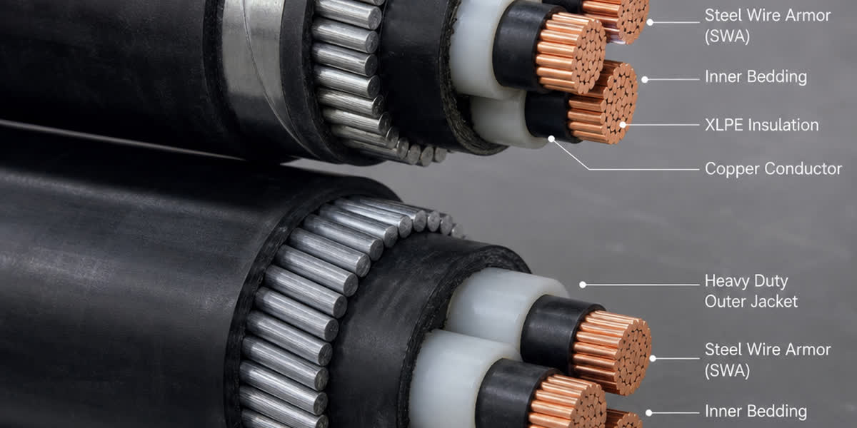
An OPGW cable consists of three primary functional components:
- Optical Unit: One or more loose tubes or stainless steel tubes containing optical fibers, protected from moisture and mechanical stress
- Strengthening Layers: Metallic wires (aluminum-clad steel, aluminum alloy, or a combination) arranged in concentric layers around the optical unit
- Outer Protection: Corrosion-resistant metallic outer layer providing impact resistance and lightning withstand capability
Common OPGW Designs
OPGW cables are available in several construction types, each suited to different installation conditions and performance requirements:
| Design Type | Optical Unit Protection | Common Applications |
|---|---|---|
| Stainless Steel Tube (SST) | Single central tube (1–48 fibers) | Most widely used, excellent moisture barrier, standard for HV/EHV lines |
| Loose Tube (LT) | Multiple gel-filled loose tubes | Higher fiber count (48–144+ fibers), easier splicing |
| Central Loose Tube (CLT) | Single large loose tube | Moderate fiber count, good temperature performance |
| Stainless Steel Tube Stranded (SSTS) | Multiple stranded SST units | Very high fiber counts, specialized applications |
Fiber Count and Configuration
OPGW fiber counts typically range from 12 to 96 fibers per cable, with configurations supporting up to 288 fibers in specialized designs:
- 12–24 fibers: Standard for protection signaling and basic SCADA
- 24–48 fibers: Typical for new transmission lines with operational telecom needs
- 48–96 fibers: Smart grid applications with distributed sensing and broadband
- 96+ fibers: Backbone telecom networks and utility ISP services
Fiber Types and Optical Design
The optical fibers are typically ITU-T G.652.D (standard single-mode fiber, zero dispersion at 1310 nm) or G.655 (non-zero dispersion-shifted fiber for DWDM applications at 1550 nm). For short-reach applications within substations, multimode fiber (G.651.1, 50/125 µm OM3/OM4) is occasionally specified. Hybrid configurations combining G.652.D for protection signaling with G.655 for DWDM backbone traffic are common in utility networks spanning 100–300 km between repeater stations.
Manufacturing: Fiber Excess Length and Stranding
Two manufacturing parameters determine the long-term optical performance of OPGW:
- Fiber excess length (FEL): Typically controlled at 0.2–0.5%, this deliberate slack allows the fiber to survive the elongation of the metallic structure under tension, ice and wind loads without strain-induced attenuation.
- Stranding precision: Armour wires are stranded around the optical unit in controlled helical layers. Precise lay length and tension control prevent the optical unit from being crushed or deformed during the stranding process.
These parameters are verified by type tests per IEEE 1138 and IEC 60794-4-20, including stress-strain behavior, temperature cycling and vibration fatigue — which is why OPGW from qualified manufacturers ships with full type-test certificates.
Key Performance Parameters
Mechanical Performance
The metallic conductor layers of OPGW are typically constructed from aluminum-clad steel (ACS) wires or a combination of ACS and aluminum alloy (AAAC) wires, providing tensile strength equivalent to or exceeding traditional ground wires. Key mechanical parameters include:
- Rated Breaking Strength (RBS): 40–200 kN depending on conductor cross-section (typically 50–150 mm² metallic cross-section)
- Elastic Modulus: 70–160 GPa (varies with ACS/AAAC ratio)
- Coefficient of Linear Expansion: 12–18 × 10⁻⁶ /°C
- Weight per Unit Length: 0.2–1.5 kg/m
Electrical Performance
OPGW must safely conduct fault currents without damaging the optical fibers:
- DC Resistance at 20°C: 0.1–0.8 Ω/km
- Short-Circuit Current Capacity: 8–80 kA (0.1–1.0 s duration)
- Maximum Fault Temperature: 200°C (300°C for special heat-resistant designs)
- Lightning Impulse Withstand: Per IEEE 1138 and IEC 60794-4-20
During a phase-to-ground fault, the OPGW must carry the entire fault current without exceeding its maximum allowable temperature. The sealed metallic tube protects the fibers from this thermal event, provided the short-circuit rating has been correctly matched to the line.
Optical Performance
- Attenuation: ≤ 0.35 dB/km @ 1310 nm, ≤ 0.20 dB/km @ 1550 nm (G.652.D)
- Attenuation Change Under Load: ≤ 0.05 dB after tensile loading to 60% RBS
- Temperature-Induced Attenuation Shift: ≤ 0.05 dB over −40°C to +80°C range
- Splice Loss (typical): 0.02–0.10 dB per fusion splice
Standards at a Glance
| Standard | Region | Key Focus |
|---|---|---|
| IEEE 1138 | North America | OPGW design, type testing, installation requirements |
| IEC 60794-4-20 | Europe, Asia, Africa, Middle East | Family specification for OPGW |
| ITU-T G.652 / G.655 | Global | Single-mode fiber optical parameters |
| GB/T 7424.4 / DL/T 832 | China | National OPGW standards |
IEEE 1138 covers mechanical testing (breaking strength, stress-strain, creep, vibration fatigue), electrical testing (short-circuit withstand, lightning impulse, corona) and optical testing. IEC 60794-4-20 is the equivalent international family specification used across Europe, Asia, Africa and the Middle East, with operation from −40°C to +80°C as standard (extended −60°C to +85°C for special designs). For a complete standards reference table covering IEC, IEEE, ASTM, CIGRE and Chinese standards, see our OPGW Selection Guide.
Selection Essentials
The two parameters that drive OPGW sizing are short-circuit rating and breaking strength. The minimum metallic cross-section can be estimated with:
S_min = I² × t / K
Where S_min is the minimum metallic cross-section (mm²), I the symmetrical fault current (kA), t the fault duration (seconds), and K a material constant (ACS: ~137, AAAC: ~200 for ΔT = 80°C rise).
For existing towers, the new OPGW must match or be lighter than the existing shield wire to avoid tower reinforcement. For full electrical, mechanical and fiber parameter selection steps, see our OPGW Selection Guide.
Installation Guidelines
Pre-Installation Planning
- Conduct a route survey to identify access points, road crossings and sensitive areas
- Verify fiber continuity and attenuation with an OTDR before stringing
- Confirm pulling line tension rating, swivel connections and load capacity
Stringing Operations
- Maximum pulling tension: Do not exceed 60% of RBS (per IEEE 1138 and IEC 60794-4-20)
- Minimum bending radius: 20× cable diameter during installation, 10× after installation
- Sheave diameter: Minimum 40× cable diameter (50× recommended for fiber protection)
- Pulling speed: 5–15 m/min maximum, to prevent fiber strain
- Swivel use: Always use a non-rotating swivel between pulling line and OPGW to prevent cable untwisting
Fiber Splicing and Testing
- Use core-alignment fusion splicers for single-mode fibers (typical loss < 0.05 dB)
- Test each splice and full span with bidirectional OTDR at 1310 nm and 1550 nm
- Record baseline attenuation for future network monitoring
For a complete step-by-step field procedure — including sag-tension calculations, maintenance schedules and troubleshooting — see our OPGW Installation & Maintenance: Complete Field Guide.
Splicing Enclosures and Hardware
Proper termination of OPGW at transmission towers requires specialized hardware:
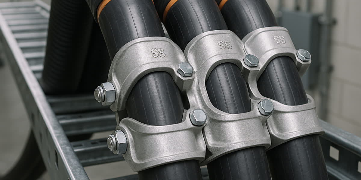
- Dead-End Clamps: Preformed helical rod types are recommended — they distribute load evenly without damaging the optical unit
- Suspension Clamps: Armor-rod type for tangent towers, with vibration damper attachment provisions
- Vibration Dampers: Stockbridge-type dampers tuned to the aeolian vibration frequency of the span; high-wind areas may require 2–3 sets per span
- Splice Enclosures: Stainless steel or polymer enclosures rated for outdoor exposure, with capacity for 12–96 fiber splices. IP68-rated enclosures prevent water ingress — a leading cause of long-term attenuation drift
- Down-Lead Cables: Fiber optic drop cables protected in stainless steel or PVC conduit from the tower attachment point to the splice enclosure
- Joint Boxes: Typically mounted 2–4 meters above ground on the tower leg, sized to accommodate spare fiber storage and future splicing
Hardware selection must be matched to the specific OPGW diameter and RBS — undersized clamps crush the optical unit, while oversized clamps allow slippage and fretting fatigue.
Applications in Modern Power Systems
Smart Grids and Grid Modernization
OPGW forms the physical communication backbone for smart grid applications:
- Wide-Area Monitoring Systems (WAMS): Real-time phasor measurement unit (PMU) data transmission at millisecond intervals over 1000+ km distances
- Adaptive Protection Schemes: Line differential protection requiring < 5 ms latency over fiber optic links
- Distributed Temperature Sensing (DTS): Raman-based DTS using OPGW fibers to monitor conductor temperature along entire line sections
- Distributed Acoustic Sensing (DAS): Vibration monitoring for intrusion detection, conductor galloping and ice formation monitoring
Renewable Energy Integration
- Wind Farm Collector Systems: OPGW provides ground wire protection for 110–220 kV collector lines and SCADA communication for turbine control
- Solar PV Power Plants: Connecting large-scale solar farms (100+ MW) to the transmission grid via OPGW-equipped lines
- Hydroelectric Plant Communications: OPGW along transmission lines from remote hydro plants provides reliable communication where cellular and satellite links are impractical
Cross-Border Interconnectors
International power interconnectors rely on OPGW for:
- High-reliability protection signaling between different utility control areas
- Market data exchange and energy trading communications
- Synchronized phasor measurements across national boundaries
- Broadband connectivity in remote border regions
OPGW vs. Alternative Fiber-on-Tower Solutions
| Feature | OPGW | ADSS (All-Dielectric Self-Supporting) | Wrap Cable |
|---|---|---|---|
| Installation method | Replace existing shield wire | Install below shield wire | Wrap around existing conductor |
| Fiber capacity | 12–96 fibers (up to 288) | 12–144 fibers | 6–48 fibers |
| Lightning protection | Yes (serves as ground wire) | No | No |
| Mechanical continuity | Yes (replaces ground wire) | No | No |
| Typical cost per km | Medium–High | Medium | Low |
| Suitable for new lines | Yes (designed in) | Yes | No (retrofit only) |
| Suitable for retrofit | Yes (if tower loading allows) | Yes | Yes |
While ADSS and wrap cables offer lower-cost alternatives for fiber installation on existing lines, only OPGW provides the combined function of ground wire protection and fiber optic communication. For new transmission lines, OPGW is nearly always the preferred solution. Our product page for OPGW Cable provides complete specifications including fiber count options, mechanical properties and short-circuit ratings.
FAQ
Q1: How are optical fibers protected inside an OPGW cable? Fibers are sealed inside stainless steel or aluminum tubes filled with thixotropic gel. The tube provides a moisture barrier and mechanical protection, while the gel cushions the fibers against vibration. Fiber excess length of 0.2–0.5% is built in during manufacturing so the fibers stay strain-free under normal operating tension.
Q2: What is the difference between stainless steel tube and loose tube OPGW designs? Stainless steel tube (SST) designs house fibers in a single sealed central tube — the best moisture barrier, suited to standard HV/EHV lines. Loose tube (LT) designs use multiple gel-filled tubes, allowing higher fiber counts (48–144+) and easier splicing, at the cost of a slightly larger diameter.
Q3: What hardware is needed to install OPGW on a tower? Dead-end (tension) clamps for angle and terminal towers, suspension clamps for tangent towers, vibration dampers for aeolian vibration control, splice enclosures for fiber termination, and down-lead protection conduits. All hardware must match the specific OPGW diameter and RBS.
Q4: How is OPGW spliced and terminated? Fibers are fusion-spliced with core-alignment splicers (typical loss < 0.05 dB), then protected in an outdoor-rated splice enclosure mounted on the tower leg. Every splice and span is verified with bidirectional OTDR testing at 1310 nm and 1550 nm, with baseline attenuation recorded for future monitoring.
Q5: Can OPGW be installed on existing towers without modification? Only if the tower's ground wire attachment points can accommodate the OPGW's weight and tension — a structural analysis is required. If loads are too high, options include a lighter OPGW design (more aluminum alloy, less steel) or an ADSS alternative. Full selection guidance is in our OPGW Selection Guide.
Q6: What are the main applications of OPGW beyond protection signaling? Beyond teleprotection and SCADA, OPGW fibers enable wide-area monitoring (WAMS/PMU), distributed temperature and acoustic sensing (DTS/DAS), renewable plant SCADA, and utility broadband/ISP services — often via DWDM on G.655 fibers.
Conclusion
OPGW is a critical infrastructure component for modern power transmission systems, uniquely combining lightning protection with fiber optic communication in a single, reliable design. Understanding its construction — fiber units, tube designs, armour layers — and specifying the correct hardware is what turns a good cable into a reliable, 30+ year communication backbone.
When planning your next project, start with our OPGW Selection Guide for standards and sizing, then use this guide for construction and hardware details, and our OPGW Installation & Maintenance: Complete Field Guide for field execution.
👉 Browse our OPGW product range 👉 OPGW Selection Guide: Standards, Specifications & Engineering Practice 👉 Contact our team
📬 Sales inquiries: sales@sitongcable.com | 📞 Phone: +86-371-69176007