Cable Pulling Tension and Sidewall Pressure Calculation: Engineering Guide to Conduit Fill, Jam Ratio, and Maximum Pulling Length
Cable Pulling Tension and Sidewall Pressure Calculation: Engineering Guide to Conduit Fill, Jam Ratio, and Maximum Pulling Length
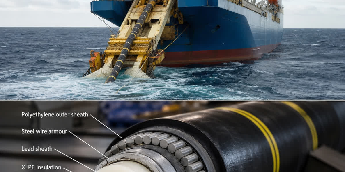
Mastering cable pulling tension and sidewall bearing pressure (SWBP) calculations is the foundation of damage-free installation for underground, conduit, and duct bank transmission systems. When installing high-performance underground power cables or armored and unarmored power cable systems across complex duct geometry, excessive mechanical stress can irreversibly damage the outer jacket, copper tape screen, semiconducting layers, and polymeric insulation. As utility networks scale and industrial distribution voltages increase, power engineers and electrical contractors must perform rigorous pre-installation pulling tension and sidewall pressure analyses adhering to IEEE 525, IEEE 1210, AEIC CG5, and NEC Chapter 9 requirements.
Zhengzhou SiTong Cable Co., Ltd. (SiTong Cable) manufactures precision-engineered medium-voltage and low-voltage cable assemblies designed for demanding trench, conduit, and duct-bank installations. Drawing upon more than two decades of international power infrastructure manufacturing experience, our application engineering team has formulated this definitive technical guide. Here, we unpack the mechanical principles, mathematical equations, geometric risks (conduit fill and jam ratios), and pull-direction optimization strategies necessary to ensure zero-defect underground cable installation.
1. Mechanical Stress Modes During Cable Pulling
Pulling a heavy insulated power cable into an underground raceway subjects the cable assembly to four distinct mechanical stress vectors:
        Pulling Winch (Tension T2)
                   ▲
                   │
         ══════════╪══════════ (Conduit Wall)
        ───────┬───┴───┬────── (Outer Jacket)
               │ Cable │       SWBP = T / R (Radial Force at Bend)
        ───────┴───────┴──────
         ═════════════════════
- Longitudinal Tensile Stress (Pulling Tension, $T$): The axial mechanical force applied along the conductor core or outer pulling grip. Exceeding the material yield stress causes plastic elongation of copper or aluminum strands, permanent cross-sectional necking, and localized thermal hot-spots during operational energization.
- Radial Compressive Stress (Sidewall Bearing Pressure, SWBP): The radial thrust pressing the cable against the inner conduit wall as it negotiates a curved bend. High SWBP crushes the outer jacket, deforms cross-linked polyethylene (XLPE) or ethylene propylene rubber (EPR) insulation, and wrinkles copper tape electromagnetic shields.
- Frictional Shear Stress: The drag generated by the coefficient of dynamic friction ($\mu$) between the cable jacket (PE, PVC, or LSZH) and the inner conduit material (PVC, HDPE, RTRC, or galvanized steel).
- Torsional Twisting: Torque generated when multi-conductor assemblies or uneven triplexed cables pass through out-of-plane compound bends.
To prevent structural damage, engineers must calculate the cumulative pulling tension at every raceway transition and verify that sidewall bearing pressure remains strictly within manufacturer-certified boundaries.
2. Fundamental Pulling Tension Equations
Underground conduit runs consist of alternating straight sections and horizontal/vertical bends. The tension calculation proceeds sequentially from the cable payout reel ($T_0$) to the pulling winch ($T_{final}$).
A. Straight Horizontal Runs
In a straight horizontal raceway, tension increases linearly as a function of cable weight, length, dynamic friction coefficient, and the weight correction factor:
$$T_2 = T_1 + (\mu \times W \times L \times w)$$
Where: * $T_2$ = Pulling tension at the end of the straight run (N or lbf) * $T_1$ = Tension at the entry of the section (N or lbf; $T_0$ is reel back-tension, typically 200–450 N) * $\mu$ = Coefficient of dynamic friction between cable jacket and conduit surface (dimensionless) * $W$ = Total weight of the cable per unit length (N/m or lbf/ft) * $L$ = Length of the straight conduit section (m or ft) * $w$ = Weight correction factor (accounting for multiple cables crowding in a raceway; $w = 1.0$ for a single cable)
B. Vertical Inclines and Declines
When pulling cables along slopes or vertical risers: * Pulling Upward (Incline): $T_2 = T_1 + [L \times W \times (\sin\theta + \mu \cdot \cos\theta \cdot w)]$ * Pulling Downward (Decline): $T_2 = T_1 + [L \times W \times (-\sin\theta + \mu \cdot \cos\theta \cdot w)]$
Where $\theta$ represents the angle of inclination from the horizontal plane. When pulling downward, if $\mu \cdot \cos\theta \cdot w < \sin\theta$, gravitational pull exceeds frictional drag, creating a runaway risk that requires controlled braking at the payout reel.
C. Curved Bends (Capstan Friction Model)
When a cable transitions through a curved conduit bend under back-tension $T_1$, the normal force against the inner curve increases dynamically. The tension amplification follows Euler-Eytelwein capstan mechanics:
$$T_2 = T_1 \times e^{(\mu \times w \times \theta_{rad})}$$
Where: * $e$ = Base of natural logarithms ($\approx 2.71828$) * $\theta_{rad}$ = Angle of the conduit bend in radians ($\theta_{rad} = \theta_{deg} \times \frac{\pi}{180}$) * For a standard $90^\circ$ elbow ($\theta = \frac{\pi}{2} \approx 1.571\text{ rad}$), with $\mu = 0.35$ and $w = 1.0$: $$T_2 = T_1 \times e^{(0.35 \times 1.571)} = T_1 \times e^{0.5498} \approx T_1 \times 1.733$$
This exponential multiplier demonstrates why entering a bend with high incoming tension ($T_1$) produces extreme exit tensions and destructive sidewall bearing forces.
3. Sidewall Bearing Pressure (SWBP) Mechanics and Limits
Sidewall Bearing Pressure (SWBP) represents the radial crushing force exerted on the cable insulation and jacket per unit length of bend radius. It is mathematically formulated as:
$$SWBP = \frac{T_2}{R}$$
Where: * $SWBP$ = Sidewall bearing pressure expressed in kilonewtons per meter (kN/m) or pounds-force per foot (lbf/ft) * $T_2$ = Cable pulling tension exiting the curved bend (kN or lbf) * $R$ = Centerline bend radius of the conduit (meters or feet)
Cable Configuration Impact on SWBP
When pulling multiple single-conductor cables through a bend, the contact geometry dramatically alters how the radial crushing force is distributed:
| Cable Configuration | Contact Geometry | SWBP Calculation Formula | Engineering Description |
|---|---|---|---|
| Single Conductor | Point line contact | $SWBP = \frac{T}{R}$ | Tension acts directly along the single cable centerline against conduit wall. |
| Three Cables (Cradled) | Cradled side-by-side | $SWBP = \frac{3w - 2}{3} \times \frac{T}{R}$ | Center cable experiences the maximum crushing force; outer cables wedge against sidewalls. |
| Three Cables (Triangular / Trefoil) | Triplexed bundle | $SWBP = \frac{w}{2} \times \frac{T}{R}$ | Two bottom cables contact the raceway; top cable presses down, dividing load. |
Maximum Permissible SWBP Thresholds
Exceeding established SWBP thresholds leads to micro-cracking of semiconducting conductor screens, dielectric breakdown under partial discharge testing, and severed copper tape shields. Recognized international standards specify the following design limits:
| Cable Construction & Insulation Type | Maximum Permissible SWBP (kN/m) | Maximum Permissible SWBP (lbf/ft) | Governing Failure Mechanism |
|---|---|---|---|
| XLPE / EPR Power Cable (Copper Tape Shield) | 6.57 kN/m | 450 lbf/ft | Tape shield elongation, wrinkle distortion, insulation indentation |
| XLPE / EPR Power Cable (Wire Shield / Neutral) | 7.30 kN/m | 500 lbf/ft | Wire screen imprint into extruded outer semicon layer |
| Interlocked Armored Cable (AIA / SWA) | 10.95 kN/m | 750 lbf/ft | Armor interlocking displacement, internal core pinching |
| Low-Voltage Building / Control Cable (PVC / THHN) | 4.38 kN/m | 300 lbf/ft | Thermoplastic cold-flow deformation under sustained pulling force |
| High-Performance Heavy Industrial Cable (HDPE Jacket) | 10.22 kN/m | 700 lbf/ft | High-modulus polyethylene jacket resists radial deformation |
4. Maximum Allowable Pulling Tension Thresholds
The maximum allowable pulling tension ($T_{max}$) depends strictly on the attachment method: pulling directly by the conductor cores via a pulling eye, or pulling via an external woven-wire basket grip (Kellems grip).
Attachment Method A: Pulling Eye (Attached to Conductor Cores)
[Conductor Strands] ═════► Soldered/Crimped to Steel Lug ──► Winch Line
Stress Limit: Copper = 70 N/mm² (10,000 psi) | Aluminum = 50 N/mm² (7,000 psi)

Attachment Method B: Wire Basket Grip (Pulling Sock)
[Cable Jacket] ░░░░░░░░░► Woven Mesh Friction ────────────► Winch Line
Stress Limit: Max 4.45 kN (1,000 lbf) or limited by jacket shear strength
A. Pulling via Conductor Pulling Eye
When pulling eyes are mechanically crimped or welded directly to the phase conductors, tensile stress transfers directly to the metallic core strands:
$$T_{max} = A \times \sigma_{max}$$
Where: * $A$ = Total cross-sectional area of metallic phase conductors ($mm^2$ or circular mils, excluding screens and armor) * $\sigma_{max}$ = Maximum allowable tensile stress of the conductor metal: * Soft Annealed Copper: $70\text{ N/mm}^2$ (approx. $10,000\text{ psi}$) * Aluminum (1350-H19 Hard-Drawn): $50\text{ N/mm}^2$ (approx. $7,000\text{ psi}$) * Aluminum Alloy (AA-8000 Series / 6201): $55\text{ N/mm}^2$ (approx. $8,000\text{ psi}$)
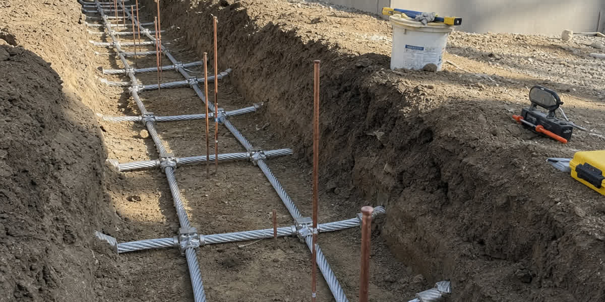
When terminating to pulling equipment or transitioning between high-capacity distribution lines, electrical contractors frequently install heavy-duty bimetallic cable lugs and compression terminals to guarantee structural and galvanic integrity.
B. Pulling via Cable Basket Grip (Pulling Sock)
When pulling by the outer jacket using a mesh basket grip, pulling force transmits via friction into the jacket and underlying sheath layers. Tensile limits are substantially lower: * Single-Conductor Non-Armored Cable: $T_{max} \le 4.45\text{ kN}$ ($1,000\text{ lbf}$) or jacket shear rating, whichever is less. * Three-Conductor / Triplexed Non-Armored Cable: $T_{max} \le 8.90\text{ kN}$ ($2,000\text{ lbf}$). * Jacket Tensile Stress Ceiling: Do not exceed $10\text{ N/mm}^2$ calculated across the outer jacket cross-sectional area.
5. Raceway Geometry: Conduit Fill, Clearance, and Jam Ratio
Mechanical calculations often fail not because the straight run is too long, but because raceway geometric anomalies cause severe physical wedging.
A. Conduit Fill Rules (NEC Chapter 9, Table 1)
Conduit fill expresses the ratio of total cable cross-sectional area to the internal cross-sectional area of the conduit:
$$\text{Conduit Fill (\%)} = \frac{\sum d_{cable}^2}{D_{conduit}^2} \times 100\%$$
- 1 Cable in Conduit: Maximum allowable fill = 53%
- 2 Cables in Conduit: Maximum allowable fill = 31% (prevents high friction from dual-cable side-by-side wedging)
- 3 or More Cables in Conduit: Maximum allowable fill = 40%
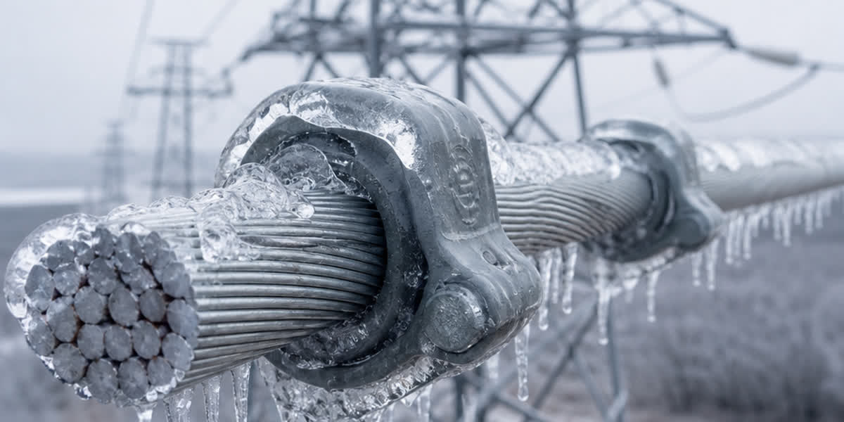
Maintaining compliance ensures sufficient thermal dissipation under continuous operating loads and provides clearance for pulling lubricants. When connecting raceways to utility poles or overhead substations, engineers route cables through overhead line fittings and hardware designed to support vertical weight transitions safely.
B. Clearance Ratio
Clearance ($C$) represents the physical gap between the uppermost cable in a raceway and the conduit crown:
$$C = D_{internal} - 1.05 \times d_{cable_bundle}$$
Engineers must maintain a minimum clearance of 12.7 mm (0.5 inches) for medium-voltage cables and 6.35 mm (0.25 inches) for low-voltage cables to avoid binding against conduit irregularities.
C. Jam Ratio Mechanics: The Fatal Trap
The Jam Ratio occurs when three single-conductor cables pull through a bend. If the ratio of internal conduit diameter ($D$) to external cable outside diameter ($d$) falls between 2.8 and 3.2, the cables can shift from a triangular arrangement into a flat, cradled profile that binds transversely across the conduit bore:
        JAM RATIO = D / d

       Dangerous Zone: 2.8 < D/d < 3.2
       ───────────────────────────────
          ( O   O   O )   ◄ Cables wedge flat across diameter D!
       ───────────────────────────────
       Frictional lockup occurs; tension spikes exponentially;
       Jacket and insulation suffer severe shearing damage.
$$\text{Jam Ratio} = \frac{D_{conduit_ID}}{d_{cable_OD}}$$
- Jam Ratio < 2.8: The cables cannot squeeze flat; they remain securely locked in a triangular geometry.
- Jam Ratio 2.8 to 3.2: CRITICAL DANGER ZONE. Cables shift unpredictably into a flat profile, wedging tightly against the conduit walls. Tension spikes catastrophically to the winch stall point, tearing the cable jacket.
- Jam Ratio > 3.2: The conduit diameter is sufficiently generous that cables pass freely side-by-side without mechanical jamming.
6. Friction Coefficients ($\mu$) and Weight Correction Factor ($w$)
Dynamic Friction Coefficients ($\mu$)
Cable pulling lubricant is mandatory for all underground cable installations. The lubricant forms an active hydrodynamic boundary layer that dramatically reduces frictional drag.
| Conduit Material | Cable Jacket: PVC (Dry / Lube) | Cable Jacket: PE / HDPE (Dry / Lube) | Cable Jacket: LSZH (Dry / Lube) |
|---|---|---|---|
| Rigid PVC Schedule 40/80 | 0.50 / 0.20 | 0.40 / 0.15 | 0.55 / 0.25 |
| HDPE Smoothwall Duct | 0.45 / 0.18 | 0.35 / 0.12 | 0.50 / 0.22 |
| Galvanized Rigid Steel (GRS) | 0.55 / 0.25 | 0.45 / 0.20 | 0.60 / 0.28 |
| Fiberglass (RTRC) | 0.50 / 0.20 | 0.38 / 0.15 | 0.52 / 0.24 |
Note: In calculations requiring safety conservatism, design engineers routinely adopt a design friction coefficient of $\mu = 0.30$ to $0.35$ with lubricant to account for dirt, conduit misalignment, and thermal field fluctuations.
Weight Correction Factor ($w$)
When multiple cables occupy a conduit, they exert normal forces against each other as well as the conduit wall, increasing effective drag:
- Single Cable: $w = 1.0$
- Three Cables in Cradled Configuration ($D/d > 3.2$): $$w = 1 + \frac{4}{3} \times \left(\frac{d}{D - d}\right)^2$$
- Three Cables in Triangular Configuration ($D/d < 2.8$): $$w = \frac{1}{\sqrt{1 - \left(\frac{d}{D - d}\right)^2}}$$
7. Comparative Pull Direction Optimization Analysis
A primary principle of cable pulling engineering states: The total pulling tension depends heavily on pull direction, even through the identical raceway profile.
Case Study: Substation Feeder Duct Run
Consider a 15kV distribution feeder consisting of three single-conductor $300\text{ mm}^2$ copper XLPE cables installed in a 150 mm PVC duct. Total cable bundle weight is $12\text{ kg/m}$ ($117.7\text{ N/m}$). * Route profile: Reel $\rightarrow$ Straight Section 1 ($150\text{ m}$) $\rightarrow$ $90^\circ$ Bend ($R = 1.5\text{ m}$) $\rightarrow$ Straight Section 2 ($30\text{ m}$) $\rightarrow$ Winch. * Friction coefficient $\mu = 0.25$; weight correction factor $w = 1.15$; bend angle $\theta = 1.571\text{ rad}$.
Profile Layout:
Reel [A] ─── 150m Straight ───► [B] 90° Bend (R=1.5m) ───► [C] 30m Straight ───► Winch [D]
Direction 1: Pulling from A to D (Long Straight Run First)
- Tension at B (after 150m straight): $$T_B = 150\text{ m} \times 117.7\text{ N/m} \times 0.25 \times 1.15 = 5,076\text{ N}$$
- Tension at C (after $90^\circ$ bend, $e^{\mu \cdot w \cdot \theta} = e^{0.25 \times 1.15 \times 1.571} = e^{0.4517} = 1.571$): $$T_C = T_B \times 1.571 = 5,076 \times 1.571 = 7,974\text{ N}$$
- Sidewall Bearing Pressure at Bend: $$SWBP = \frac{T_C}{R} = \frac{7,974\text{ N}}{1.5\text{ m}} = 5,316\text{ N/m} = \mathbf{5.32\text{ kN/m}}$$ (Safe, below 6.57 kN/m limit)
- Final Winch Tension at D (after 30m straight): $$T_D = T_C + (30\text{ m} \times 117.7 \times 0.25 \times 1.15) = 7,974 + 1,015 = \mathbf{8,989\text{ N}}$$
Direction 2: Pulling from D to A (Reversed Direction: Bend Near Reel)
- Tension at C (after 30m straight): $$T_C = 30\text{ m} \times 117.7\text{ N/m} \times 0.25 \times 1.15 = 1,015\text{ N}$$
- Tension at B (after $90^\circ$ bend): $$T_B = 1,015 \times 1.571 = 1,595\text{ N}$$
- Sidewall Bearing Pressure at Bend: $$SWBP = \frac{1,595\text{ N}}{1.5\text{ m}} = 1,063\text{ N/m} = \mathbf{1.06\text{ kN/m}}$$ (Massive 80% reduction in crushing stress!)
- Final Winch Tension at A (after 150m straight): $$T_A = 1,595 + 5,076 = \mathbf{6,671\text{ N}}$$ (Overall tension drops from 8.99 kN to 6.67 kN — a 26% reduction!)
Golden Engineering Rule: Always pull cables so that sharp bends and high-angle elbows are situated as close to the payout reel as possible. Never pull into a sharp bend at the end of a long, heavy straight run.
8. SiTong Cable Technical Capabilities & Quality Assurance
As an international tier-1 power cable and conductor manufacturer, Zhengzhou SiTong Cable Co., Ltd. builds rugged durability into every cable drum:
- Robust Jacket Compounding: Extruded high-density polyethylene (HDPE), oil-resistant PVC, and flame-retardant LSZH outer sheaths formulated for high tear resistance, low dynamic friction, and elevated hot-deformation thresholds.
- Reinforced Barrier Sheaths: Continuous radial moisture barriers incorporating copolymer-coated aluminum or copper tapes bonded to the outer jacket, engineered to withstand aggressive pulling tensions and high sidewall compressive forces.
- Comprehensive Conductor Portfolio: High-conductivity electrolytic copper and electrical-grade aluminum conductors spanning underground power cables, heavy-duty medium- and low-voltage power cables, and utility-grade overhead conductors including AAC, AAAC, and ACSR.
- Engineering Pre-Calculation Support: SiTong Cable's technical service center provides project-specific route evaluations, pulling tension modeling, conduit fill validation, and custom drum length packaging to eliminate mid-duct splicing risks.
9. Step-by-Step Field Pulling Quality Control Checklist
To avoid costly field failures, electrical site engineers should execute this seven-point verification checklist before starting the pulling winch:
Pre-Pull Quality Protocol:
[ ] 1. Mandrel Proving (95% Conduit Diameter Proving Pig)
[ ] 2. Duct Cleaning & Water Evacuation Swabbing
[ ] 3. Pre-Lubrication & Continuous Lube Pump Setup
[ ] 4. Calibrated Dynamometer with Auto-Tension Cutoff
[ ] 5. Anti-Torsion Swivel Coupling Inspection
[ ] 6. Minimum Dynamic Bend Radius Verification (12x to 15x OD)
[ ] 7. Post-Pull Outer Jacket Spark Testing & DC Sheath Verification
- Conduit Mandrel Proving: Pull a flexible cylindrical mandrel sized to 95% of inner conduit diameter through the raceway to identify flattened ducts, crushed elbows, or joint lips before feeding cable.
- Duct Swabbing: Pull wire brushes and high-density foam swabs to clear sharp sand, standing water, and construction debris.
- Controlled Lubrication: Apply pulling lubricant continuously at the conduit entrance and inject downstream before major bends. Ensure lubricant chemical compatibility with cable jacket polymers (IEEE 1210).
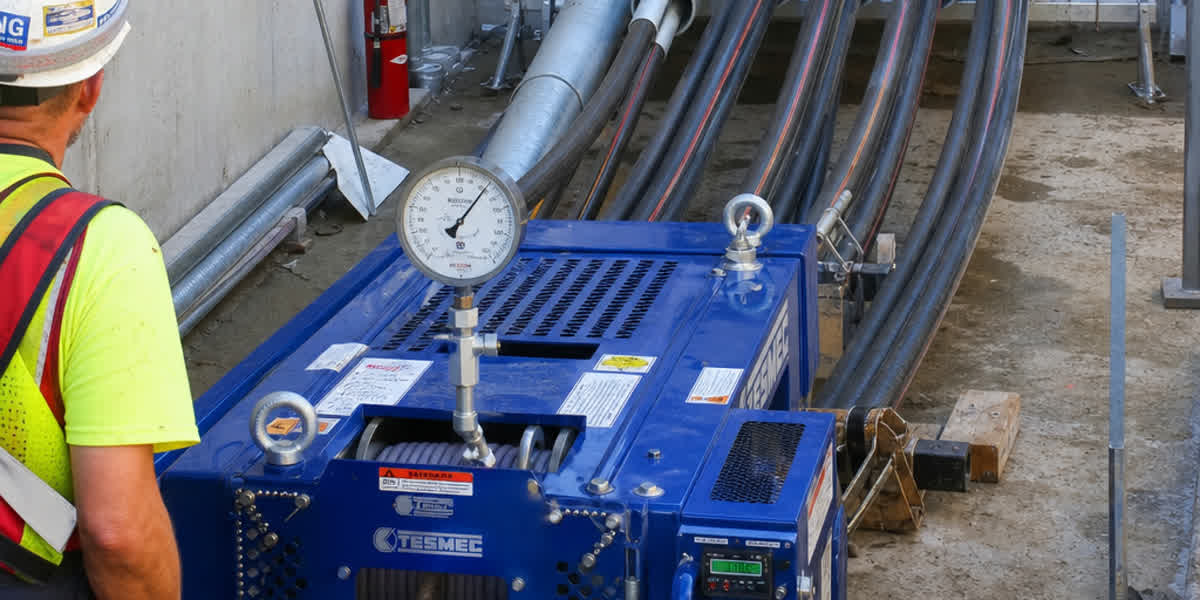
- Dynamometer Calibration: Employ a digital tension-monitoring pulling winch equipped with an automatic load-limiting cutoff set to 90% of the calculated $T_{max}$.
- Anti-Torsion Swivels: Install a calibrated swivel link between the pulling eye and winch rope to relieve internal winding torque.
- Bend Sheaves & Rollers: Ensure corner roller pulleys provide a bending radius matching or exceeding the cable's minimum dynamic bending radius under tension (typically $15 \times \text{OD}$ for unarmored cables, $20 \times \text{OD}$ for tape-shielded/armored cables).
- Post-Installation Sheath Testing: Subject the cable jacket to an outer sheath integrity test (e.g., 5 kV to 10 kV DC sheath test per IEC 60229) to verify zero jacket perforation before civil backfilling.
10. Frequently Asked Questions (FAQ)
Q1: What is the primary difference between static and dynamic bending radius during cable pulling?
A: The static minimum bending radius applies to a cable resting in its final, un-tensioned operating position (typically $8\times$ to $12\times$ cable outside diameter depending on construction). The dynamic bending radius applies while the cable is actively moving under pulling tension through pulleys, sheaves, or conduit elbows. Because axial tension exerts strong radial inward forces against the core, dynamic bending radius requires larger dimensions (typically $15\times$ to $20\times$ cable OD) to prevent excessive sidewall pressure and shield distortion.
Q2: Why is the Jam Ratio range of 2.8 to 3.2 considered hazardous for 3-cable pulls?
A: When three cables travel through a bend, they naturally position themselves in a triangular configuration ($D/d < 2.8$). When the conduit diameter expands relative to cable diameter ($D/d > 3.2$), they have ample space to rest side-by-side or slide past each other. However, in the 2.8 to 3.2 transition zone, cables can shift from triangular into a flat planar configuration that matches the conduit's internal width. The three cables wedge transversely across the raceway bore, creating a mechanical friction lock that abruptly halts the pull and damages jackets.
Q3: When should a pulling eye be chosen over a woven wire basket grip?
A: A pulling eye attached directly to the conductor strands is required whenever calculated pulling tension exceeds $4.45\text{ kN}$ ($1,000\text{ lbf}$) for single-conductor cables or $8.9\text{ kN}$ ($2,000\text{ lbf}$) for triplexed assemblies, or whenever pulling medium- and high-voltage cables through long duct banks with multiple bends. Basket grips rely on frictional shear along the outer jacket; high forces can stretch the jacket, damage underlying tape shields, or cause the grip to slip off entirely.
Q4: How does pulling lubricant affect pulling tension and sidewall pressure?
A: High-performance polymeric pulling lubricants reduce the dynamic coefficient of friction ($\mu$) from dry levels of $0.40$–$0.60$ down to $0.15$–$0.25$. Because bend tension amplification follows the exponential capstan formula ($T_2 = T_1 \cdot e^{\mu \cdot w \cdot \theta}$), cutting friction in half yields dramatic, non-linear reductions in exit tension. This directly slashes sidewall bearing pressure ($SWBP = T / R$), allowing longer single pulls, reducing civil manhole requirements, and keeping mechanical stress safely within design margins.
Q5: Can SiTong Cable supply custom continuous lengths to eliminate underground joints?
A: Yes. Zhengzhou SiTong Cable Co., Ltd. manufactures continuous drum lengths tailored to specific project route dimensions and maximum allowable reel weights. Providing continuous single lengths eliminates unnecessary underground joints, which represent the most common thermal and dielectric failure points in power distribution systems. Our engineering staff provides coordinated pulling tension and reel weight calculations during project planning.
Conclusion & Project Consultation
Flawless underground cable deployment requires balancing structural cable limits with raceway geometry and friction mechanics. Calculating pulling tension, sidewall bearing pressure, conduit fill, and jam ratios beforehand protects capital assets, guarantees long-term dielectric performance, and prevents costly site repairs.
For technical specifications, customized cable sizing, or project quotes, connect directly with our application engineering department:
👉 Browse our complete Underground Cable range 👉 Explore Medium & Low Voltage Power Cables 👉 Review Overhead Conductors (ACSR / AAAC / AAC) 👉 Inspect Heavy-Duty Cable Lugs and Terminations 👉 Contact SiTong Cable Technical & Engineering Support
📬 Sales & Engineering Inquiries: sales@sitongcable.com | 📞 Technical Hotline: +86-371-69176007