Instalación y Mantenimiento de STACIR/AW (HTLS): Guía de Campo Completa para Líneas Aéreas de Alta Temperatura y Baja Flecha
Instalación y Mantenimiento de STACIR/AW (HTLS): Guía de Campo Completa para Líneas Aéreas de Alta Temperatura y Baja Flecha
Guía de campo completa para instalar y mantener conductores STACIR/AW (HTLS) — control de flecha con núcleo de invar, tendido a tensión, empalmes a compresión, inspección térmica y resolución de problemas.
1. Introducción
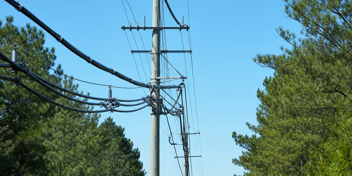
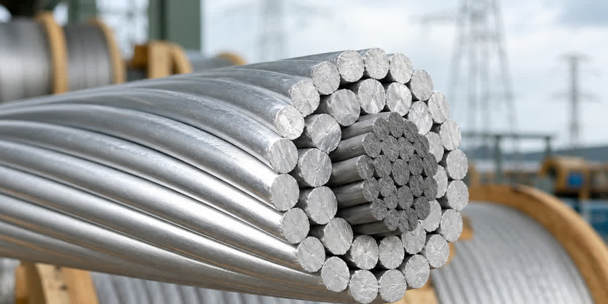
Los conductores de Alta Temperatura y Baja Flecha (HTLS) son la herramienta principal de los proyectos de ampliación de capacidad en líneas de transmisión, y el STACIR/AW (Conductor de Aluminio Supertermorresistente Reforzado con Invar) es una de las variantes con mayor experiencia operativa en servicio. A diferencia del conductor ACSR convencional, cuyo límite térmico de operación continua es de aproximadamente 90–100 °C, el STACIR/AW está diseñado para operar a 150 °C de forma continua y hasta 210 °C en condiciones de emergencia — mientras su núcleo de invar (aleación hierro-níquel, ~36 % Ni), con un coeficiente de expansión térmica (CET) de aproximadamente 3 × 10⁻⁶/°C, mantiene el crecimiento de la flecha en una fracción del que produciría un núcleo de acero. El resultado: ganancias de ampacidad del 50–100 % sobre la geometría de torres existentes, sin reconstruir estructuras.
Sin embargo, estas ventajas de rendimiento solo se materializan si el conductor se manipula, tiende, empalma y mantiene correctamente. El STACIR/AW no es un conductor ACSR que funciona en caliente — su núcleo de invar, sus alambres de aluminio termorresistente dopado con circonio (ZTAL) y sus temperaturas de operación elevadas cambian cada paso del flujo de instalación y mantenimiento: las tensiones de tendido deben respetar la distribución de carga compuesta núcleo/alambre, los troqueles de compresión deben dimensionarse para el núcleo de invar, y la inspección térmica se convierte en una actividad programada y no en una verificación ocasional.
Esta guía está escrita para ingenieros de líneas de transmisión, supervisores de campo, linieros y cuadrillas de mantenimiento de servicios públicos. Cubre la preparación previa a la instalación, la ingeniería de flecha-tensión, el procedimiento completo de tendido, las pruebas posteriores a la instalación, un programa de mantenimiento rutinario, la resolución de problemas y la seguridad. Para criterios de selección, tablas de especificaciones y comparación de normas internacionales, consulte nuestra guía complementaria Conductor HTLS (STACIR/AW): Guía Técnica Completa.
2. Preparación Previa a la Instalación
2.1 Recepción y Almacenamiento
| Verificación | Criterio de Aceptación |
|---|---|
| Condición del carrete | Sin tablones rotos; bridas intactas; sin señales de daño por impacto |
| Rotación del carrete | Flechas visibles; el conductor se desenrolla por la parte superior del carrete |
| Sellado de extremos | Ambos extremos sellados contra la entrada de humedad |
| Prueba de muestra | Tomar muestra de 3 m por carrete; verificar cableado y sentido de capa según ASTM B941 |
| Almacenamiento | Horizontal sobre durmientes ≥150 mm del suelo; cubrir con lona transpirable; no apilar más de 3 carretes |
| Temperatura | Almacenar lejos de fuentes de calor — los alambres ZTAL pierden resistencia si se recocen en almacenamiento |
Crítico: Los carretes de STACIR/AW no deben almacenarse en contacto directo con el suelo ni en agua estancada. El núcleo de invar revestido de aluminio es resistente a la corrosión, pero el contacto prolongado con humedad en las terminaciones sin revestir puede iniciar actividad galvánica. Si un carrete se ha almacenado más de 6 meses, gírelo 90° cada 3 meses para evitar el asentamiento del núcleo.
2.2 Lista de Verificación de Herramientas y Equipos
| Categoría de Herramienta | Elementos | Notas de Aplicación |
|---|---|---|
| Tiro | Mordazas de tiro (tipo Kellems u ojos de tiro a compresión), giratorios, poleas de tendido | La garganta de la polea debe ser ≥20× el diámetro del conductor; usar mínimo 762 mm (30 in) para 400 mm² y superiores |
| Tensado | Tensora con rueda de cabrestante, soportes de carrete, freno | La garganta de la rueda debe estar revestida de neopreno o poliuretano; sin contacto acero-aluminio |
| Empalme | Troqueles de compresión de tensión total, bomba hidráulica (≥100 MPa), cortadoras | Troqueles según la hoja de datos del fabricante del conector — los troqueles para núcleo de invar difieren de los de acero ACSR |
| Flecha | Tránsito/teodolito, tableros de flecha, sonda de temperatura, dinamómetro | La flecha a temperatura de diseño de 150 °C requiere corrección precisa de temperatura ambiente |
| Vibración | Amortiguadores Stockbridge, separadores, varillas de armadura | Según diseño — obligatorio para vanos >200 m o donde exista riesgo de vibración eólica |
| Puesta a tierra | Pinzas de tierra, cables de unión, tierras personales de protección | La tensión inducida en circuitos adyacentes energizados puede superar los 100 V — siempre conectar a tierra la sección de trabajo |
| Medición | Pirómetro óptico o cámara IR, microóhmetro | Para verificación de empalmes posteriores a la instalación e imágenes térmicas |
2.3 Plan de Instalación
Antes de la movilización, el contratista debe preparar un plan de tendido que cubra: longitudes de secciones de tiro (típicamente 3–6 km entre ubicaciones de montaje), ubicación de poleas y puntos de medición de flecha, protección de cruces (carreteras, ferrocarriles, líneas de BT/MT), y la secuencia de tendido a tensión según IEEE 524. Para trabajos de reconducción en corredores energizados, confirme las ventanas de corte y coordine con el centro de control — la mitigación de tensión inducida es parte del plan, no una ocurrencia posterior.
⚠️ Advertencia: Nunca tirar del STACIR/AW con un cable de acero directamente sobre el conductor. Utilice siempre un giratorio entre el cable de tiro y la mordaza, y mantenga la tensión de tendido por debajo del 20 % de la resistencia nominal a la tracción (RTS), o el máximo recomendado por el fabricante, el que sea menor.
3. Cálculos de Ingeniería
3.1 Parámetros de Diseño
| Parámetro | Valor Típico STACIR/AW | Notas |
|---|---|---|
| Temperatura máxima de operación continua | 150 °C | Los alambres ZTAL conservan resistencia a 150 °C |
| Temperatura máxima de emergencia | 210 °C | Corto plazo (≤2 h acumuladas por evento) |
| CET del núcleo | ~3 × 10⁻⁶/°C | Invar Fe-36Ni |
| CET del alambre | ~23 × 10⁻⁶/°C | Aleación de aluminio ZTAL |
| Módulo inicial | ~70–80 GPa compuesto | Depende de la relación de áreas alambre/núcleo |
| Fluencia (creep) | Baja a 150 °C | Aleación ZTAL diseñada para resistencia a la fluencia a alta temperatura |
3.2 Cálculo Flecha-Tensión (Comportamiento de Punto de Rodilla)
El STACIR/AW presenta un comportamiento de punto de rodilla similar al ACSS: por debajo de la temperatura de punto de rodilla (típicamente 80–120 °C según la relación de áreas alambre/núcleo), tanto los alambres de aluminio como el núcleo de invar comparten la tensión; por encima del punto de rodilla, los alambres de aluminio se han expandido y relajado, y el núcleo de invar soporta casi toda la carga mecánica. Esto es lo que mantiene la flecha plana a alta temperatura.
Utilice el método de modelo compuesto según CIGRE TB 324 (Métodos de Cálculo de Flecha-Tensión para Líneas Aéreas), nunca la aproximación parabólica simple utilizada para ACSR:
Flecha = (w × L²) / (8 × H)
donde w = peso unitario (N/m), L = vano regulador (m), H = tensión horizontal (N). La tensión H debe resolverse iterativamente para el compuesto de dos materiales, considerando:
- Condición inicial de tendido (sin carga, 15 °C)
- Condición final después de fluencia (ver §3.3)
- Condición de operación continua a 150 °C
- Condición de emergencia a 210 °C
- Carga de hielo + viento según IEC 60826 o zonas de carga locales
Regla de verificación: La flecha a 150 °C no debe exceder el límite de distancia al suelo de diseño, y la tensión a −5 °C con carga de hielo no debe exceder el 40 % de la RTS (o el valor especificado por el proyecto).
3.3 Compensación por Fluencia
Los alambres de aleación de aluminio fluyen con el tiempo, y a temperaturas elevadas la fluencia se acelera. Según CIGRE TB 244, las instalaciones HTLS deben considerar:
| Tipo de Fluencia | Causa | Magnitud (típica) | Mitigación |
|---|---|---|---|
| Fluencia inicial | Asentamiento de alambres y compactación entre capas | 0,1–0,3 % de deformación en los primeros 6 meses | Pre-esfuerzo o corrección de flecha en el tendido |
| Fluencia térmica | Exposición prolongada a 150 °C | 0,05–0,15 % en 20 años | Usar curvas de fluencia del fabricante; diseñar la flecha final en consecuencia |
| Fluencia del núcleo | Despreciable para invar | <0,02 % | El invar no fluye apreciablemente a ≤210 °C |
Enfoque práctico: Instale a la temperatura de tendido con la flecha ajustada para la condición final (con fluencia), o aplique una sobre-tensión inicial durante 1–2 horas ("pre-esfuerzo") para acelerar la fluencia inicial fuera del vano. Confirme el enfoque con el fabricante del conductor antes del tendido.
4. Procedimiento de Instalación
4.1 Montaje y Tendido
- Posicionar el equipo: Coloque la tensora en el extremo de tiro y la tensora de rueda de cabrestante en la ubicación de montaje, alineadas con la dirección de la línea.
- Instalar poleas: Cuelgue las poleas de tendido en cada estructura; verifique que los asientos giren libremente y estén dimensionados para el diámetro del conductor (garganta ≥20× diámetro).
- Pasar la línea piloto: Tienda una línea piloto sintética (nunca de acero) a través de las poleas.
- Conectar la mordaza de tiro: Conecte la línea piloto a la mordaza de tiro mediante un giratorio. Para 400 mm² y superiores, utilice un ojo de tiro a compresión que se cortará después — no tire de una mordaza temporal a alta tensión.
- Tender el conductor: Mantenga la tensión de modo que el conductor nunca toque el suelo, árboles o estructuras. Tensión máxima de tendido: 20 % de la RTS (o 25 % con aprobación previa), y nunca exceda la carga nominal de la polea.
- Medir la flecha: Usando el método de medición (tránsito + tableros de flecha o dinamómetro), ajuste la flecha al valor de la tabla de tendido corregido por la temperatura ambiente real en el momento. No ajuste la flecha "a ojo" — a 150 °C de diseño, un error de 10 °C en el tensado cambia significativamente la distancia al suelo.
- Transferir al soporte: Transfiera el conductor de las poleas a las grapas de suspensión o conjuntos de varillas de armadura en cada estructura. Asegúrese de instalar las almohadillas de la grapa (neopreno o similar) — está prohibido el contacto directo metal-aluminio.
- Anclar: Instale los anclajes de tensión total según las instrucciones del fabricante. Los anclajes STACIR/AW utilizan accesorios a compresión con el núcleo de invar insertado en el barril del núcleo.
4.2 Empalmes y Compresión
El empalme es la actividad de mayor riesgo para los conductores HTLS — un empalme deficiente se convierte en un punto caliente a 150 °C.
| Paso | Requisito |
|---|---|
| Selección del conector | Use conectores clasificados para operación continua a 210 °C, probados según IEC 61238-1 / IEEE 575 |
| Preparación del núcleo | Pele los alambres de aluminio con cuidado; no dañe los alambres del núcleo de invar |
| Selección de troqueles | Use troqueles especificados para la combinación núcleo/alambre STACIR/AW — NO reutilice troqueles ACSR (el núcleo de invar es más duro que el acero galvanizado y requiere compresión diferente) |
| Compresión | Empalme de tensión total: comprima primero el barril del núcleo, luego el manguito de aluminio del centro hacia afuera; presión hidráulica ≥100 MPa según hoja de datos del conector |
| Verificación | Después de la compresión, mida la resistencia a través de la unión con un microóhmetro — debe ser ≤1,1× la resistencia de la longitud equivalente de conductor; marque y registre las ubicaciones de las uniones |
| Empalmes de reparación | Solo empalmes de reparación a tensión aprobados por el fabricante; nunca use grapas de canal paralelo atornilladas para reparaciones de tensión total en vanos |
💡 Consejo: Para STACIR/AW de 400 mm² y superiores, use empalmes a compresión de dos piezas (núcleo + aluminio). Los empalmes de una pieza solo son aceptables por debajo de 240 mm² y solo con aprobación del fabricante. Documente cada empalme con coordenadas GPS — esto es esencial para el programa de inspección térmica de la §6.
4.3 Mitigación de Vibración
La vibración eólica es el principal riesgo de fatiga en líneas HTLS, y la temperatura de operación elevada no la reduce. Instale según diseño:
| Contramedida | Aplicación | Norma |
|---|---|---|
| Amortiguadores Stockbridge | Vanos >200 m; 1–2 por extremo de vano | IEEE 664 |
| Separadores | Conductores en haz (2 o 4 subconductores) | IEEE 524 |
| Varillas de armadura | Puntos de suspensión y donde las grapas contactan el conductor | IEC 61284 |
| Registradores de vibración | Vanos largos, cruces de ríos, terreno abierto | — |
Instale los amortiguadores a 0,5–1,5 m de la grapa de suspensión según la tabla de colocación del fabricante. Reapriete las abrazaderas de los amortiguadores en la primera inspección anual.
5. Inspección y Pruebas Posteriores a la Instalación
| Elemento de Inspección | Criterio de Aceptación | Método |
|---|---|---|
| Verificación de flecha | Flecha medida dentro de ±2 % del valor de diseño a temperatura ambiente | Levantamiento con tránsito o telémetro láser |
| Resistencia de empalmes | ≤1,1× resistencia de longitud equivalente | Microóhmetro en cada unión |
| Corona / interferencia de radio | Sin corona audible/visible a tensión nominal; RI dentro de límites CISPR 18-2 | Inspección nocturna + medidor de RI |
| Continuidad de tierra | <1 Ω entre estructuras y tierra | Comprobador de tierra tipo pinza |
| Par de torsión del herraje | Todos los pernos al par especificado; pasadores de chaveta instalados | Llave dinamométrica |
| Superficie del conductor | Sin mellas, abrasiones ni alambres aplastados por poleas/grapas | Inspección visual + dron |
Primera energización: Después de energizar, realice un levantamiento termográfico dentro de las 24 horas bajo carga. Documente el perfil térmico como línea base del programa de mantenimiento.
6. Programa de Mantenimiento Rutinario
| Frecuencia | Actividad de Mantenimiento |
|---|---|
| Mensual (primeros 3 meses) | Verificación visual de nuevos empalmes y anclajes por signos de sobrecalentamiento |
| Semestral | Imágenes térmicas de todos los empalmes, anclajes y puentes — comparar con línea base; cualquier unión >10 °C sobre el conductor adyacente debe señalarse |
| Anual | Medición de flecha y análisis de tendencia; inspección y reapriete de amortiguadores; verificación de herrajes; auditoría de despeje de vegetación |
| Cada 2 años | Estudio de corona/RI; inspección visual de aisladores y herrajes (dron o escalada) |
| Cada 5 años | Inspección completa de línea: superficie del conductor, verificación de corrosión en secciones costeras, pruebas de resistencia de empalmes por muestreo |
| Cada 10 años | Auditoría profunda: re-verificar flecha-tensión contra diseño, revisar historial térmico (monitores de temperatura del conductor si están instalados), planificación de reemplazo |
⚠️ Umbral de imágenes térmicas: En líneas HTLS, un empalme que funciona 10 °C por encima del conductor adyacente a carga de 150 °C es una falla en desarrollo — programe reparación en 30 días. A 20 °C por encima, retire la línea de servicio o transfiera la carga inmediatamente.
7. Resolución de Problemas Comunes
| Problema | Causa Probable | Solución |
|---|---|---|
| Empalme caliente detectado en estudio térmico | Barril del núcleo mal comprimido; troqueles incorrectos; puente flojo | Reducir capacidad de línea, re-comprimir o reemplazar el empalme según procedimiento del fabricante |
| Flecha mayor que el diseño a alta carga | Fluencia no compensada en el tendido; temperatura de tensado incorrecta | Re-verificar con software de flecha-tensión; planificar re-tensado si se viola la distancia |
| Vibración / marcas de fatiga cerca de grapas | Amortiguadores faltantes o mal ubicados; sin varillas de armadura | Instalar amortiguadores según tabla; inspeccionar alambres por grietas de fatiga |
| Corrosión en sección costera | Núcleo sin revestir expuesto en empalme; revestimiento dañado | Reemplazar la sección afectada; aplicar inhibidor de corrosión en uniones |
| RI / ruido audible de noche | Contaminación superficial, gotas de agua o alambres dañados | Limpiar o reparar; verificar anillos de corona en terminaciones |
| Deslizamiento de mordaza durante el tendido | Tamaño de mordaza incorrecto; tensión demasiado alta | Detener el tendido, re-montar con mordaza correcta; inspeccionar el conductor por daños |
| Efecto "jaula de pájaro" (birdcaging) en el empalme | Corte incorrecto; troquel no coincide | Re-empalmar con el juego de troqueles correcto; cortar alambres dañados |
8. Consideraciones de Seguridad
| Peligro | Precaución |
|---|---|
| Tensión inducida en línea desenergizada | Conectar a tierra ambos extremos de la sección de trabajo; usar tierras personales de protección; unir el equipo de tendido |
| Alta tensión de tiro (hasta 20 % RTS) | Mantener al personal fuera de la trayectoria de tiro; usar barreras y líneas de retención |
| Exposición a temperatura elevada (diseño 150–210 °C) | Asumir que el conductor puede estar caliente durante el mantenimiento en líneas cargadas; usar imágenes térmicas antes de tocar |
| Caídas durante trabajos en torres | Protección completa contra caídas; prácticas de posicionamiento según normativa local |
| Herramientas de compresión (≥100 MPa hidráulico) | Capacitación del operador; nunca colocar las manos entre troqueles; usar protectores |
| Exposición a corona / campo eléctrico | Mantener distancias en estructuras energizadas; usar prácticas de trabajo seguras contra CEM |
9. Preguntas Frecuentes (FAQ)
P1: ¿Se puede tender STACIR/AW con la misma tensión que ACSR? No. La tensión de tendido del STACIR/AW normalmente se limita al 20 % de la RTS (frente al 15–25 % del ACSR según proyecto), pero la diferencia crítica es la distribución de carga compuesta: como el núcleo de invar soporta la mayor parte de la carga por encima del punto de rodilla, la tensión de tendido debe verificarse contra el modelo compuesto de flecha-tensión según CIGRE TB 324, no con la aproximación parabólica del ACSR.
P2: ¿Cuál es la temperatura de punto de rodilla del STACIR/AW? El punto de rodilla es la temperatura a la que los alambres de aluminio se han expandido lo suficiente como para transferir su tensión al núcleo — típicamente 80–120 °C para STACIR/AW según la relación de áreas alambre/núcleo. Por encima del punto de rodilla, el crecimiento de la flecha se rige casi por completo por el CET de ~3 × 10⁻⁶/°C del núcleo de invar, razón por la cual la flecha permanece plana hasta 210 °C.
P3: ¿Son aceptables los troqueles de compresión estándar de ACSR para empalmes STACIR/AW? No. El núcleo de invar tiene características de dureza y diámetro diferentes a las del alambre de núcleo de acero galvanizado. Utilice siempre el juego de troqueles y el programa de compresión del fabricante del conector para el tamaño específico de STACIR/AW. Usar troqueles ACSR es una causa común de uniones mal comprimidas, de alta resistencia, que se sobrecalientan a 150 °C.
P4: ¿Con qué frecuencia deben realizarse imágenes térmicas en una línea HTLS? Como mínimo semestralmente, y dentro de las 24 horas posteriores a la primera energización para establecer la línea base. Se recomiendan controles mensuales durante los primeros 3 meses después de la instalación. Cualquier empalme a más de 10 °C sobre la temperatura del conductor adyacente requiere acción en 30 días; 20 °C requiere reducción de carga inmediata.
P5: ¿El STACIR/AW requiere herrajes especiales para operación a 210 °C? Sí. Todos los accesorios — anclajes, empalmes, grapas de suspensión, varillas de armadura, puentes — deben estar clasificados para operación continua a 210 °C. Los herrajes estándar de ACSR clasificados para 90–100 °C pierden propiedades mecánicas y se corroen a las temperaturas de operación HTLS. Especifique herrajes HTLS en la adquisición.
P6: ¿Se pueden reutilizar las torres ACSR existentes al reconducir con STACIR/AW? En la mayoría de los casos sí — ese es el valor central de la reconducción HTLS. Sin embargo, las cargas de la torre deben re-verificarse: el STACIR/AW suele ser más pesado que el ACSR que reemplaza, y la mayor tensión a baja temperatura (si la hay) debe estar dentro de los límites de torre y cimentación. Se requiere una evaluación estructural completa según IEC 60826.
P7: ¿Cuál es el vano máximo para STACIR/AW? No hay un máximo fijo, pero los vanos superiores a 400 m requieren datos de flecha-tensión específicos del fabricante a 150 °C y 210 °C, más un estudio de vibración. El STACIR/AW se ha utilizado en cruces de ríos y aplicaciones de vanos largos; consulte al fabricante para vanos superiores a 600 m.
P8: ¿Cómo se detecta la corrosión en un núcleo de invar revestido de aluminio? El revestimiento de aluminio protege galvánicamente al núcleo de invar, pero la corrosión puede iniciarse donde el revestimiento está dañado (empalmes, puntos de grapa o daños de manipulación). La inspección visual anual más controles de resistencia específicos en secciones costeras o industriales revelarán problemas en desarrollo — un aumento del 20 % en la resistencia de una unión es un fuerte indicador de corrosión en desarrollo.
10. Referencias y Normas
| Norma | Descripción |
|---|---|
| ASTM B941 | Conductores de aluminio cableados concéntricamente, reforzados con invar revestido de aluminio (STACIR/AW) — norma de construcción principal |
| IEEE 524 | Guía para la instalación de conductores de líneas de transmisión aéreas |
| IEEE 738 | Norma para calcular la relación corriente-temperatura de conductores aéreos desnudos |
| IEEE 664 | Guía para la medición en laboratorio de las características de disipación de potencia de los amortiguadores de vibración eólica |
| IEC 61089 | Conductores aéreos cableados concéntricamente de alambre redondo |
| IEC 60826 | Criterios de diseño de líneas de transmisión aéreas |
| IEC 61284 | Líneas aéreas — Requisitos y ensayos para herrajes |
| IEC 61238-1 | Conectores de compresión y mecánicos para cables de energía — Parte 1 |
| IEC 61597 | Conductores eléctricos aéreos — Métodos de cálculo para conductores desnudos cableados |
| CIGRE TB 244 | Conductores para la ampliación de capacidad de líneas aéreas |
| CIGRE TB 324 | Métodos de cálculo de flecha-tensión para líneas aéreas |
| CISPR 18-2 | Características de interferencia de radio de líneas eléctricas aéreas — Métodos de medición |
11. Acerca de Sitong Cable
Sitong Cable es un fabricante profesional de conductores aéreos, incluyendo conductor ACSR, conductor AAAC, conductor AAC y ACAR, producidos según las normas ASTM B941, IEC 61089 y BS 215. Nuestro equipo de ingeniería brinda soporte en estudios de flecha-tensión, planes de tendido y capacitación en instalación para proyectos HTLS y de conductores convencionales en todo el mundo.
👉 Explore nuestra gama de conductores ACSR 👉 Conductor HTLS (STACIR/AW): Guía Técnica Completa — Estándares, Especificaciones y Selección 👉 Contacte a nuestro equipo
📬 Consultas de ventas: sales@sitongcable.com | 📞 Teléfono: +86-371-69176007
Esta guía fue preparada por el equipo de ingeniería de Sitong Cable. Todos los datos técnicos hacen referencia a ASTM B941, IEEE 524, IEEE 738, IEC 61089, IEC 60826, CIGRE TB 244 y CIGRE TB 324.