Overhead Line Wildfire Mitigation & Bushfire Hardening: Covered Conductors (Tree Wire, Spacer Cable & ABC) vs Bare Conductors in High Fire Threat Districts (IEEE 1246, ICEA S-121-733, EN 50397-1, AS/NZS 3675)
Overhead Line Wildfire Mitigation & Bushfire Hardening: Covered Conductors (Tree Wire, Spacer Cable & ABC) vs Bare Conductors in High Fire Threat Districts (IEEE 1246, ICEA S-121-733, EN 50397-1, AS/NZS 3675)
Overhead power distribution lines traversing High Fire Threat Districts (HFTD), wildland-urban interfaces (WUI), and densely forested corridors represent one of the most critical ignition vulnerabilities in modern utility operations. Catastrophic wildfire outbreaks in California, Australia, the Mediterranean basin, and Latin America have demonstrated that conventional bare overhead conductors such as standard ACSR conductor and AAAC conductor are highly susceptible to vegetation-induced phase-to-phase clashing, tree branch bridging, conductor slap, and wire-down ground faults. Under severe windstorms and prolonged drought conditions, electrical arcing across bare conductors produces incandescent molten metal particles and ground flashovers capable of instantly igniting dry forest fuels.
To combat this escalating operational hazard, electrical utilities worldwide are executing comprehensive grid hardening programs that replace bare overhead lines with insulated covered conductor architectures, notably multi-layer covered conductors and Tree Wire, Spacer Cable systems, and low/medium-voltage Aerial Bundled Cable (ABC). This comprehensive technical guide provides electrical utility engineers, transmission system operators (TSOs), distribution system operators (DSOs), and EPC contractors with a rigorous engineering analysis of wildfire ignition physics, material science architectures, comparative performance metrics, international compliance standards (IEEE 1246, ICEA S-121-733, EN 50397-1, AS/NZS 3675), and installation best practices.
1. Wildfire Ignition Mechanisms in Overhead Power Distribution
Understanding the electro-thermal physics of overhead line ignitions is essential for selecting appropriate mitigation technologies. Ignition events in overhead power networks fall into four primary physical categories:
+-----------------------------------------------------------------------------------+
|               OVERHEAD LINE WILDFIRE IGNITION MECHANISMS                          |
+------------------------------------+----------------------------------------------+
| 1. Direct Vegetation Contact       | Tree branch falls across bare phases ->      |
|    (High-Impedance Faults)         | Continuous micro-arcing & burning embers    |
+------------------------------------+----------------------------------------------+
| 2. Conductor Clashing & Slap       | High wind gusts cause phase oscillation ->   |
|    (Phase-to-Phase Arcing)         | Inter-phase arc spatter & molten aluminum   |
+------------------------------------+----------------------------------------------+
| 3. Conductor Break & Fall to Ground| Mechanical fatigue/tree impact ->            |
|    (Phase-to-Earth Arcing)         | Energetic ground arc igniting forest floor  |
+------------------------------------+----------------------------------------------+
| 4. Hardware Tracking & Puncture    | Insulator pollution/flashover ->             |
|    (Apparatus Failure)             | Dry-band arcing & pole-top fire              |
+------------------------------------+----------------------------------------------+
1.1 Vegetation Contact & High-Impedance Faults (HIF)
When a tree branch makes contact with two energized bare phases or bridges an energized bare phase to grounded neutral/crossarm hardware, electrical current flows through the wood matrix. Because live wood exhibits non-linear resistance ($10\text{ k}\Omega$ to $1\text{ M}\Omega$), the resulting fault current is frequently below the pickup threshold of conventional overcurrent relays (typically $<50\text{ A}$). This High-Impedance Fault (HIF) generates intense localized $I^2 R$ thermal dissipation. The moisture in the bark vaporizes, forming dry-band carbonized conductive paths that ignite into continuous open flame within seconds, dropping burning wood embers onto dry undergrowth.
1.2 Phase Clashing and Molten Particle Spatter
During severe wind gusts, differential aerodynamic drag and turbulence cause bare conductors to oscillate asynchronously. When horizontal or vertical clearance between adjacent phases is breached, a phase-to-phase fault arc erupts at thousands of degrees Celsius. The electric arc instantly vaporizes surface aluminum, ejecting superheated molten metal droplets (temperatures exceeding $1,200^\circ\text{C}$). These droplets retain sufficient thermal enthalpy to ignite fine dry fuels (1-hour and 10-hour timelag fuels) several meters below the right-of-way (ROW).
1.3 Conductor Break and Wire-Down Events
Mechanical overloads caused by severe ice accumulation, falling tree trunks, or cyclic aeolian fatigue can cause complete mechanical rupture of a bare conductor. Upon striking dry soil, high-energy arcing continues until upstream reclosers or protection schemes lock out. The thermal energy released during the initial clearance cycle (often $0.5$ to $2.0\text{ seconds}$) is more than sufficient to ignite organic humus layers.
2. Hardened Conductor Technologies & Material Architectures
Grid hardening strategies deploy three primary insulated conductor technologies to eliminate contact arcing, suppress phase clashing, and reduce right-of-way clearance requirements:
MULTI-LAYER COVERED CONDUCTOR (TREE WIRE) CROSS-SECTION:
=========================================================
  [ 1. Compacted Al Conductor (AAC/AAAC/ACSR) ]
        |
        v
  [ 2. Semi-Conducting Conductor Screen (0.3-0.5 mm) ]
        |
        v
  [ 3. Inner Virgin XLPE Dielectric Layer (2.0-3.5 mm) ]
        |
        v
  [ 4. Outer Track-Resistant TR-XLPE / HDPE Layer (1.5-2.5 mm) ]
2.1 Multi-Layer Covered Conductor (Tree Wire / Covered Conductor)
Covered conductors—governed globally by ICEA S-121-733 (North America) and EN 50397-1 (Europe/International)—are unshielded insulated conductors engineered to withstand direct, momentary, or prolonged mechanical contact with tree branches without electrical flashover.
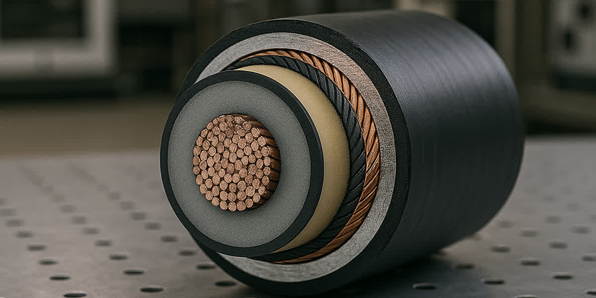
The state-of-the-art triple-extruded covered conductor architecture comprises: 1. Conductor Core: High-conductivity aluminum alloy (AAAC 6201-T81 per ASTM B399 / EN 50183) or steel-reinforced aluminum (ACSR conductor per ASTM B232 / IEC 61089) engineered for superior tensile strength and fatigue resistance. 2. Semi-Conducting Strand Screen: Extruded cross-linked semiconducting polymer layer that homogenizes the radial electrical field around conductor strand gaps, eliminating internal corona discharge and micro-void partial discharge. 3. Inner High-Dielectric Insulation: Virgin Cross-Linked Polyethylene (XLPE) possessing superior dielectric breakdown strength ($>22\text{ kV/mm}$) and thermal rating ($90^\circ\text{C}$ continuous, $250^\circ\text{C}$ short-circuit). 4. Outer Track-Resistant & UV-Stabilized Jacket: High-Density Polyethylene (HDPE) or Track-Resistant Cross-Linked Polyethylene (TR-XLPE) formulated with $>2.5\%$ fine carbon black and specialized metal hydroxide trihydrate additives. This layer provides exceptional surface hydrophobicity, abrasive cut-through resistance against tree limbs, and extreme resistance to surface tracking and erosion according to IEC 60587 (Class 1A 4.5kV rating).
2.2 Spacer Cable Systems (Compact Covered Conductor Architecture)
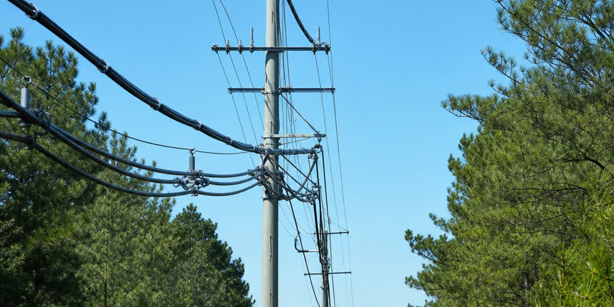
Spacer Cable systems utilize three phase-covered conductors supported by a dedicated, high-strength messenger wire (galvanized steel wire strand per ASTM A475 or aluminum-clad steel). The three phases are held in a tight triangular or diamond geometry (phase spacing of $180\text{ mm}$ to $300\text{ mm}$) by high-dielectric cycloaliphatic or polypropylene mechanical spacers installed every $10\text{ m}$ to $15\text{ m}$ along the span.
Key Wildfire Hardening Advantages: - Mechanical Shielding: The top high-tensile steel messenger intercepts falling branches and trees, absorbing impact kinetic energy before limbs reach the energized phase conductors. - Narrow Right-of-Way (ROW): Reduces ROW clearing width by $60\%\text{ to }75\%$, minimizing environmental impact and tree trimming cycles. - Zero Phase Clashing: Mechanical spacers physically prevent phase-to-phase contact under dynamic crosswinds exceeding $130\text{ km/h}$.
2.3 Low & Medium Voltage Aerial Bundled Cable (ABC)
For lower voltage secondary distribution ($0.6/1\text{ kV}$) and selected medium voltage feeders ($11\text{ kV}-33\text{ kV}$), Aerial Bundled Cable (ABC) per AS/NZS 3560, IEC 60502-1, and NF C 33-209 provides complete phase isolation. The phase cores are fully insulated with carbon-black-filled XLPE and helically twisted around an insulated or bare neutral messenger alloy conductor. Because phase surfaces carry full phase insulation thickness and are in direct physical contact, phase-to-phase flashover and direct tree contact ignition risks are effectively reduced to zero ($0\%$).
3. Engineering Parameter Comparison: Hardened vs Bare Conductors
The following matrix compares key operational and wildfire mitigation parameters across the four overhead conductor options:
| Engineering Parameter | Bare Overhead Conductor (ACSR / AAAC) | Multi-Layer Tree Wire (Covered Conductor) | Spacer Cable System (Covered + Messenger) | Aerial Bundled Cable (ABC) |
|---|---|---|---|---|
| Primary International Standards | ASTM B232, IEC 61089, BS 215 | ICEA S-121-733, EN 50397-1, AS/NZS 3675 | IEEE 1246, ICEA S-121-733 | AS/NZS 3560, IEC 60502-1, NF C 33-209 |
| Voltage Class Range | $0.4\text{ kV}\text{ to }765\text{ kV}$ | $11\text{ kV}\text{ to }38\text{ kV}$ | $11\text{ kV}\text{ to }69\text{ kV}$ | $0.6/1\text{ kV}\text{ to }36\text{ kV}$ |
| Wildfire Ignition Risk Reduction | $0\%$ (Baseline) | $85\%\text{ to }92\%$ | $94\%\text{ to }98\%$ | $>99\%$ |
| Vegetation Contact Withstand | $0\text{ seconds}$ (Instant flashover) | $200\text{ to }>2000\text{ hours}$ continuous | $500\text{ to }>3000\text{ hours}$ continuous | Indefinite (Fully rated insulation) |
| Phase Clearance Requirement | Large ($1.0\text{ m}\text{ to }3.0\text{ m}$) | Medium ($0.3\text{ m}\text{ to }0.8\text{ m}$) | Ultra-Compact ($0.18\text{ m}\text{ to }0.30\text{ m}$) | Zero ($0\text{ m}$, bundled contact) |
| Right-of-Way (ROW) Width | $12\text{ m}\text{ to }25\text{ m}$ | $6\text{ m}\text{ to }10\text{ m}$ | $3\text{ m}\text{ to }5\text{ m}$ | $2\text{ m}\text{ to }4\text{ m}$ |
| Phase Clashing Flashover Risk | High under gusting winds | Eliminated (Covering prevents arc) | Eliminated (Spacer restraint) | Eliminated (Fully twisted bundle) |
| Conductor Sag & Tension | Optimized for long spans | Moderate increase in wind/ice weight | Supported by high-strength messenger | Moderate span limitations |
| Installed Capital Cost Ratio | $1.0\times$ (Lowest upfront) | $1.25\times\text{ to }1.45\times$ | $1.60\times\text{ to }1.90\times$ | $1.50\times\text{ to }2.10\times$ |
| Undergrounding Cost Comparison | $1.0\times$ vs $6.0\times-10.0\times$ UG | $1.3\times$ vs $6.0\times-10.0\times$ UG | $1.7\times$ vs $6.0\times-10.0\times$ UG | $1.8\times$ vs $6.0\times-10.0\times$ UG |
4. Hardware Engineering, Grounding & Surge Protection in Wildfire Zones
Upgrading conductors alone is insufficient without specifying compatible high-integrity overhead line fittings and hardware accessories designed to prevent dry-band arcing and mechanical degradation.
+-----------------------------------------------------------------------------------+
|               CRITICAL HARDWARE FOR COVERED CONDUCTOR SYSTEMS                     |
+------------------------------------+----------------------------------------------+
| A. Polymeric Pin/Post Insulators   | High-hydrophobicity silicone/cycloaliphatic  |
|                                    | to prevent dry-band leakage currents         |
+------------------------------------+----------------------------------------------+
| B. Semi-Conducting Armor Ties      | Carbon-loaded polymeric ties preventing      |
|                                    | localized dielectric stress & chafing        |
+------------------------------------+----------------------------------------------+
| C. Arc Protection Devices (APD)    | Spark gap horns directing lightning arcs     |
|                                    | away from conductor covering to avoid burn   |
+------------------------------------+----------------------------------------------+
| D. Bimetallic Compression Lugs     | Friction-welded Cu/Al lugs preventing        |
|                                    | electrolytic corrosion & thermal runaway     |
+------------------------------------+----------------------------------------------+
4.1 Track-Resistant Insulators and Polymer Tie Systems
Standard porcelain or glass insulators can experience intense capacitive surface currents when supporting covered conductors in polluted, moist environments. When dew or moisture condenses on the surface, leakage currents flowing between the conductor covering and the grounded crossarm form dry bands. The resulting micro-sparks can track across porcelain heads and erode the conductor jacket.
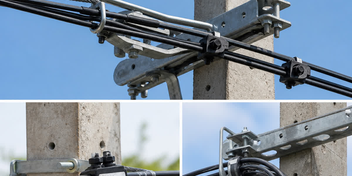
Engineering Requirement: - Deploy high-creepage silicone rubber or cycloaliphatic polymer post insulators with hydrophobicity class HC1-HC2 per IEC TS 62073. - Secure conductors using semi-conducting polymeric covered tie wires or preformed elastomeric armor rods rather than bare metallic tie wires to eliminate localized electric field concentrations and mechanical jacket chafing.
4.2 Arc Protection Devices (APD) and Lightning Burn-Down Prevention
Because covered conductors prevent lightning-induced power-frequency follow-through arcs from moving freely along the conductor (which occurs naturally on bare lines), the arc root remains stationary at the point of lightning flashover. This concentrated heat ($>10,000^\circ\text{C}$) can sever the aluminum core within $0.1\text{ to }0.3\text{ seconds}$, causing a hazardous wire-down event.
Engineering Solution: Install Arc Protection Devices (APD) or dedicated distribution surge arresters with metal arc-horns at every insulator support. The APD forces the power-frequency fault arc to ignite across the external spark gap horn, protecting the covered conductor insulation from thermal puncture and mechanical severance.
4.3 High-Current Connection Terminations & Connectors
All taps, splices, and transformer bushings must maintain absolute environmental sealing and low-resistance bonding. Utilize factory-greased compression cable lugs and bimetallic connectors with torque-limiting shear-head insulation piercing connectors (IPC per EN 50483-4). This prevents moisture ingress into the aluminum strand bundle, eliminating galvanic oxidation and hot-spot failure.
5. Quality Compliance, Standards & Qualification Testing Protocol
Engineers must ensure procured covered conductors and wildfire-hardening materials comply with the following rigorous international qualification test standards:
+-----------------------------------------------------------------------------------+
|                 COVERED CONDUCTOR QUALIFICATION TEST MATRIX                       |
+------------------------+-------------------+--------------------------------------+
| Test Designation       | Standard          | Acceptance Criteria                  |
+------------------------+-------------------+--------------------------------------+
| Tracking & Erosion     | IEC 60587 /       | No puncture or tracking at 4.5 kV    |
| Resistance Test        | EN 50397-1        | after 6 hours (Class 1A 4.5)         |
+------------------------+-------------------+--------------------------------------+
| Tree Branch Abrasion   | EN 50397-1        | Steel rod oscillating 200,000 cycles |
| Resistance Test        | Annex B           | without core exposure                |
+------------------------+-------------------+--------------------------------------+
| High-Voltage Spark     | ICEA S-121-733 /  | Continuous in-line test at           |
| Testing                | IEC 60502-1       | 15 kV - 25 kV AC without breakdown   |
+------------------------+-------------------+--------------------------------------+
| Accelerated UV &       | ASTM G154 /       | >2,000 hrs Xenon/UV exposure with    |
| Weathering Aging       | ISO 4892-2        | >=80% retention of tensile/elongation|
+------------------------+-------------------+--------------------------------------+
| Dielectric Breakdown   | IEEE 1246 /       | Minimum withstand >=30 kV AC         |
| Voltage Test           | ICEA S-121-733    | in 5-minute water immersion test     |
+------------------------+-------------------+--------------------------------------+
5.1 Inclined Plane Tracking & Erosion Test (IEC 60587 / EN 50397-1)
Specimens of the outer jacket are mounted at a $45^\circ$ angle with ammonium chloride liquid contaminant flowing across the surface under a $4.5\text{ kV}$ applied potential. The material must withstand 6 consecutive hours without developing conductive carbon tracks or erosion depth exceeding $2.5\text{ mm}$.
5.2 Tree Branch Abrasion Mechanical Test (EN 50397-1 Annex B)
A grounded steel or wooden friction rod oscillates back and forth against the energized covered conductor under a specified mechanical contact force ($20\text{ N}$ to $50\text{ N}$) for over 200,000 cycles. The covering must demonstrate zero dielectric puncturing and retain its minimum required wall thickness.
6. SiTong Cable Manufacturing Excellence for Wildfire Grid Hardening
As a premier global power cable and overhead conductor manufacturer with more than two decades of engineering excellence, Zhengzhou SiTong Cable Co., Ltd. (SiTong Cable) delivers end-to-end grid hardening solutions engineered specifically for high-risk wildfire corridors.
SITONG CABLE MANUFACTURING & HARDENING ADVANTAGES:
* TRIPLE-EXTRUSION CCV LINES: Single-pass extrusion of conductor screen, virgin XLPE, and UV-stabilized TR-XLPE/HDPE.
* PRECISION LASER GEOMETRY: Dual-axis laser diameter monitoring ensuring concentricity >95% and uniform wall thickness.
* 100% IN-LINE SPARK TESTING: High-voltage spark testers operating continuously at 25 kV AC to detect micro-pinholes.
* ADVANCED MATERIAL COMPOUNDING: Premium masterbatch carbon black (>2.5%) and non-halogen fire/tracking retardants.
* FULL ENGINEERING TESTING LAB: In-house IEC 60587 tracking test, cold bend (-40°C), and ASTM B232 mechanical testing.
SiTong Cable's specialized product portfolio for wildfire mitigation includes: 1. Tree Wire & Covered Conductors ($11\text{ kV}-38\text{ kV}$): High-conductivity compacted AAAC/ACSR conductors insulated with two-layer or three-layer TR-XLPE/HDPE compounds complying with ICEA S-121-733 and EN 50397-1. 2. Spacer Cable Assemblies: High-durability phase conductors paired with high-tensile galvanized steel wire strand messengers for storm-resilient, narrow-ROW corridors. 3. LV & MV Aerial Bundled Cables (ABC): Fully insulated self-supporting and messenger-supported bundles complying with AS/NZS 3560 and IEC 60502-1. 4. Comprehensive Hardware & Accessories: Full line of compatible polymeric post insulators, overhead line fittings and hardware accessories, and bimetallic cable lugs and connectors.
7. High-Value Engineering FAQ for Wildfire Mitigation
Q1: What is the primary difference between Tree Wire (Covered Conductor) and Fully Insulated Power Cable?
A: Tree Wire (Covered Conductor) is an unshielded insulated conductor designed specifically to prevent short-circuits and electrical arcing during temporary or prolonged physical contact with tree branches and other phases. However, because it does not possess a grounded metallic radial screen (unlike underground power cables), the outer surface carries a non-zero capacitive electrostatic voltage. Therefore, Tree Wire cannot be safely touched by personnel while energized and must always be installed on rated insulators like overhead bare conductors.
Q2: Why is Track-Resistant XLPE (TR-XLPE) or HDPE necessary for the outer covering instead of standard PVC?
A: When an energized covered conductor touches a grounded tree branch in wet or humid weather, capacitive leakage currents flow across the jacket surface. Standard PVC or non-tracking polymers rapidly decompose under micro-arcing, forming carbonized paths ("tracking") that erode the insulation and cause a phase-to-ground fault. TR-XLPE and HDPE incorporate specialized chemical scavengers and carbon black that suppress carbonization, providing outstanding tracking resistance under IEC 60587 ($4.5\text{ kV}$ Class 1A) and superior UV weatherability.
Q3: How does Spacer Cable compare to Undergrounding (Cabling) in terms of wildfire risk and total project cost?
A: While direct-burial underground cable provides the absolute highest wildfire risk reduction ($100\%$), it requires massive capital expenditures—typically $6\times\text{ to }10\times$ higher than bare overhead lines—and faces prolonged permitting and rough terrain excavation obstacles. Spacer Cable and multi-layer Tree Wire achieve an $85\%\text{ to }98\%$ wildfire ignition risk reduction at only $1.25\times\text{ to }1.90\times$ the cost of bare lines, allowing utilities to harden 5 to 8 times more corridor miles within the same capital budget.
Q4: Can existing bare conductor overhead poles be retrofitted with Tree Wire?
A: Yes. In most utility wildfire mitigation plans (such as California CPUC Wildfire Mitigation Plans), utilities perform reconductoring projects by replacing bare ACSR conductor or AAAC conductor with compacted aluminum Tree Wire on existing utility poles. Because Tree Wire is slightly heavier and has a larger aerodynamic profile under wind/ice loading, engineering pole loading calculations (per NESC or AS/NZS 7000) must be validated. Installing compacted conductors or high-strength AAAC alloy cores typically allows direct pole reuse without pole replacements.
Q5: How do Arc Protection Devices (APD) prevent covered conductor wire-down events during lightning strikes?
A: On bare conductors, lightning flashovers create power-frequency fault arcs that naturally travel along the line via electromagnetic forces until cleared. On covered conductors, the insulating jacket prevents the arc roots from moving, anchoring the intense thermal arc at a single point and burning through the aluminum core within hundreds of milliseconds. Arc Protection Devices (APD) provide sacrificial metal spark horns that intercept the arc root, discharging the fault energy into the air away from the conductor jacket and preserving mechanical integrity.
8. Conclusion & Engineering Action Plan
Hardening overhead electrical distribution infrastructure in High Fire Threat Districts is a paramount engineering priority. Transitioning from vulnerable bare overhead conductors to high-performance multi-layer covered conductors and Tree Wire, Spacer Cable systems, and Aerial Bundled Cable (ABC) drastically reduces wildfire ignition probability, enhances storm resilience, and protects communities while maintaining cost-effective capital allocation.
By combining precision triple-extrusion manufacturing, rigorous tracking-resistance compliance (IEC 60587, ICEA S-121-733, EN 50397-1), and compatible engineered hardware fittings, SiTong Cable stands as your trusted global manufacturing partner for wildfire-resilient grid modernization.
Related Product Links & Resources
👉 Browse our Covered Conductor & Tree Wire product range
👉 Tree Wire / Spacer Cable Installation & Maintenance: Complete Field Guide
👉 Contact our engineering team for technical specifications and custom designs
📬 Sales & Engineering Inquiries: sales@sitongcable.com | 📞 Phone: +86-371-69176007