Instrumentation Cable Shielding: Individual & Overall Shield (IS/OS) vs Overall Shield (OS) Engineering Guide
Instrumentation Cable Shielding: Individual & Overall Shield (IS/OS) vs Overall Shield (OS) Engineering Guide
Selecting the appropriate shielding configuration for industrial instrumentation cables is essential for preserving signal integrity in automated process environments. In oil and gas refineries, chemical processing plants, thermal power stations, and modern manufacturing facilities, sensitive analog and digital signals must navigate severe electromagnetic interference (EMI), radio-frequency interference (RFI), and ground potential differences. Understanding the technical distinctions, noise mitigation physics, and grounding architectures between Overall Shield (OS) and Individual & Overall Shield (IS/OS) cables is critical for instrumentation and control engineers.
Industrial instrumentation systems rely on low-voltage, low-current signals to monitor and control critical processes. When these microvolt-level sensor signals or 4–20 mA current loops run parallel to medium-voltage motors, variable frequency drives (VFDs), and heavy switchgear, electromagnetic coupling can induce significant noise. Specifying the wrong shielding topology leads to signal distortion, false process trips, communication packet loss, and costly downtime. As a premier global cable manufacturer, SiTong Cable produces a comprehensive control and instrumentation cable range engineered to EN 50288-7, BS 5308, and IEC 60092 standards to eliminate interference across mission-critical circuits.
1. Physics of Industrial Noise Coupling in Signal Circuits
To select between OS and IS/OS cable architectures, engineers must first evaluate how electrical noise couples into signal conductors. Industrial noise primarily manifests across three distinct physical mechanisms:
[ Industrial Noise Source: VFD, Motor, Switchgear ]
   │
   ├─► Capacitive Coupling (Electrostatic, Electric Field E) ──► Mitigated by: 100% Foil Shield + Drain Wire
   ├─► Inductive Coupling (Electromagnetic, Magnetic Field B) ──► Mitigated by: Tight Twisted Pair Pitch (<50-70mm)
   └─► Conductive / Ground Loop Coupling (Ground Potential ΔV) ──► Mitigated by: Single-Point Shield Earthing
1.1 Capacitive (Electrostatic) Coupling
Capacitive coupling occurs when a time-varying electric field ($dV/dt$) from adjacent power cables or high-voltage equipment induces an unwanted displacement current ($i_c = C_{12} \cdot \frac{dV}{dt}$) into the signal conductor through mutual capacitance ($C_{12}$). A conductive shield surrounding the signal pair intercepts these electrostatic field lines and shunts the induced displacement currents safely to ground via the drain wire before they penetrate the signal loop.
1.2 Inductive (Magnetic) Coupling
Inductive coupling arises from alternating magnetic fields ($B$) generated by heavy AC load currents ($dI/dt$) in nearby industrial power cable solutions. According to Faraday’s Law of Electromagnetic Induction, the induced noise voltage ($V_n = -M \cdot \frac{dI}{dt}$) is directly proportional to the loop area enclosed by the signal conductors and the mutual inductance ($M$).
Twisted pairs provide the primary defense against magnetic induction. By twisting the forward and return conductors at a continuous, uniform pitch (lay length), adjacent twist loops experience equal and opposite magnetic flux, canceling out the induced differential noise voltage:
$$\text{CMRR}{\text{inductive}} \approx 20 \log \right)$$} \left( \frac{V_{\text{common}}}{V_{\text{differential}}
1.3 Inter-Pair Crosstalk in Multi-Pair Cables
When multiple independent measurement channels are bundled within a single cable jacket, mutual capacitance and mutual inductance between adjacent pairs create internal crosstalk. A high-level switching pulse on Channel A can couple directly into a sensitive RTD or thermocouple reading on Channel B. Controlling this internal cross-coupling is the core engineering justification for Individual Shielding (IS).
2. Overall Shield (OS) vs. Individual & Overall Shield (IS/OS) Construction
The primary mechanical and electrical distinction between OS and IS/OS cables lies in how the aluminum-polyester shielding tape and tinned copper drain wires are applied within the cable core.
       OVERALL SHIELD (OS)                   INDIVIDUAL & OVERALL SHIELD (IS/OS)
  ┌───────────────────────────────┐         ┌─────────────────────────────────────────┐
  │  [ Outer PVC/LSZH Sheath ]   │         │    [ Outer PVC/LSZH Sheath ]            │
  │  [ Ripcord / Inner Bedding ] │         │    [ Overall Al-Mylar + Drain Wire ]    │
  │  [ Overall Al-Mylar Tape ]    │         │    [ Inner Binder / Bedding Tape ]      │
  │  [ Common Tinned Drain Wire ] │         │   ┌───────────────┐ ┌───────────────┐   │
  │   (Pair 1) (Pair 2) (Pair 3)  │         │   │ Pair 1 + IS   │ │ Pair 2 + IS   │   │
  │   (Pair 4) (Pair 5) (Pair 6)  │         │   │ (Foil + Drain)│ │ (Foil + Drain)│   │
  │   (Unshielded Twisted Pairs)  │         │   └───────────────┘ └───────────────┘   │
  └───────────────────────────────┘         └─────────────────────────────────────────┘
2.1 Overall Shield (OS) Architecture
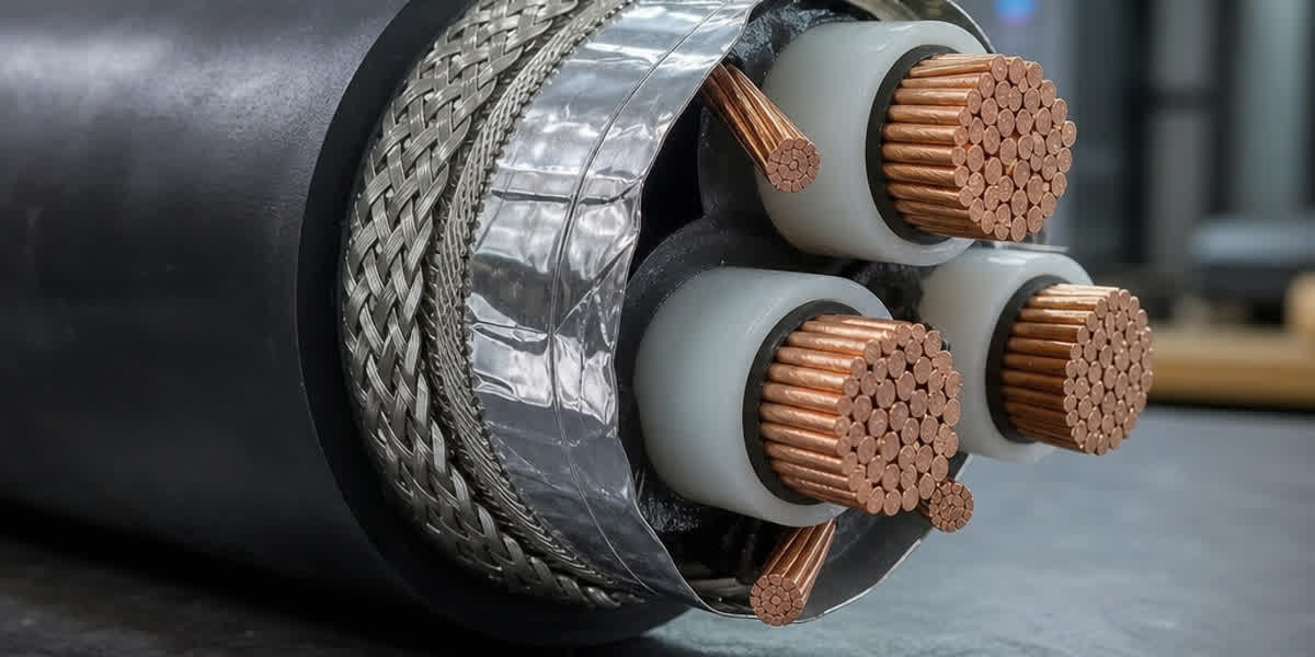
In an OS (Overall Screen / Overall Shielded) cable, multiple twisted pairs (or triads) are cabled together into a circular core. A single layer of aluminum-backed polyester tape (typically 24–50 $\mu\text{m}$ aluminum bonded to polyester) is helically or longitudinally applied with a minimum 25% overlap over the entire bundled core, backed by a continuous tinned annealed copper drain wire (typically 0.5 $\text{mm}^2$ / 20 AWG to 0.75 $\text{mm}^2$ / 18 AWG).
- Best Suited For: Uniform signal levels (e.g., all 4–20 mA current loops), single-pair runs, clean electromagnetic environments, and cost-sensitive installations where intra-cable crosstalk between channels is negligible.
2.2 Individual & Overall Shield (IS/OS) Architecture
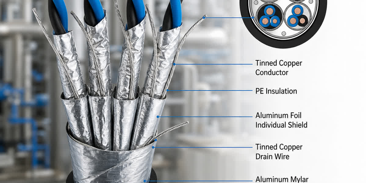
In an IS/OS (Individual Screen and Overall Screen) cable: 1. Individual Shield (IS): Each individual twisted pair (or triad) is wrapped with its own dedicated aluminum-polyester laminated foil tape (100% physical coverage) along with an individual tinned copper drain wire. An individual non-hygroscopic polyester isolation tape prevents electrical contact between adjacent individual shields. 2. Overall Shield (OS): The individually shielded pairs are then cabled together, wrapped with an overall aluminum-polyester tape and a master overall drain wire, followed by the inner bedding, optional armoring, and outer protective jacket.
- Best Suited For: Mixed signal types in the same multi-pair cable (e.g., combining 4–20 mA analog outputs, mV thermocouple inputs, and digital pulses), high-speed serial communications (RS-485 / Modbus), low-level millivolt transducer circuits, and environments with extreme external electromagnetic interference.
3. Technical Comparison: OS vs. IS/OS Cables
The following engineering matrix outlines the technical, electrical, and physical trade-offs between OS and IS/OS multi-pair instrumentation cables:
| Parameter / Feature | Overall Shielded (OS) | Individual & Overall Shielded (IS/OS) | Engineering Significance |
|---|---|---|---|
| External EMI/RFI Attenuation | High (60–80 dB) | Very High (80–110 dB) | Double shielding provides dual attenuation barriers against external fields |
| Inter-Pair Crosstalk Suppression | Moderate (30–45 dB at 10 kHz) | Exceptional (>75–90 dB at 10 kHz) | Individual foil isolates channels within the same cable bundle |
| Common Mode Rejection (CMRR) | 60–75 dB | 85–115 dB | Prevents common-mode voltages from becoming differential errors |
| Mutual Capacitance (Core-to-Core) | 75–110 pF/m | 65–95 pF/m | Lower capacitance extends maximum transmission distance for high-baud fieldbus |
| Capacitance Unbalance (Pair-to-Shield) | $\le 500\text{ pF}/500\text{m}$ | $\le 200\text{ pF}/500\text{m}$ | Critical for maintaining balance in precision RTD and bridge circuits |
| Cable Outer Diameter (OD) | Standard (Baseline) | +15% to +25% larger | Affects cable tray fill calculations and conduit sizing |
| Minimum Bending Radius | $6 \times \text{OD}$ (Unarmored) | $8 \times \text{OD}$ (Unarmored) | Requires larger junction boxes and tray turning radiuses |
| Material & Manufacturing Cost | Baseline (1.0x) | 1.35x to 1.60x | Factored against the cost of process interruption and instrumentation errors |
| Applicable Standards | EN 50288-7, BS 5308-2, UL 13 | EN 50288-7, BS 5308-1/2, UL 2250 | Full compliance with international instrumentation specifications |
4. Signal-Type Selection Matrix: When to Specify IS/OS vs. OS
Selecting the wrong cable shielding configuration can severely degrade sensor accuracy. Use this engineering selection matrix to map specific process instrumentation signals to the optimal cable architecture:
[ Process Signals ] ──► Low-Level (<100 mV, RTD, Thermocouple) ───────► MANDATORY: IS/OS
                    ──► Mixed Signals (Analog 4-20mA + Digital I/O) ────► MANDATORY: IS/OS
                    ──► High-Baud Fieldbus (Modbus RS-485, Profibus) ───► RECOMMENDED: IS/OS
                    ──► Homogeneous Analog (All 4-20mA Loops) ──────────► ACCEPTABLE: OS
                    ──► Discrete 24V DC Status / Relay Coil ────────────► ACCEPTABLE: OS
4.1 RTD Temperature Sensors (Pt100, Pt1000) & Thermocouples
- Signal Level: Millivolts ($0\text{–}50\text{ mV}$) or small resistance changes ($0.385\text{ }\Omega/^\circ\text{C}$).
- Recommendation: IS/OS with Twisted Triads or Pairs.
- Engineering Reason: Even a few microvolts of coupled crosstalk from an adjacent 4–20 mA loop or solenoid valve will introduce significant temperature measurement errors (e.g., $10\text{ }\mu\text{V}$ error $\approx 0.25^\circ\text{C}$ error in Type K thermocouples). Individual shielding isolates the microvolt circuit completely.
4.2 4–20 mA Analog Current Loops (Standard & HART Protocol)
- Signal Level: $4\text{–}20\text{ mA DC}$ with superimposed 1.2/2.2 kHz FSK digital communication (HART).
- Recommendation: OS for homogeneous bundles; IS/OS for mixed-signal multi-pair cables.
- Engineering Reason: Current loops are inherently low-impedance ($250\text{ }\Omega$ load) and resistant to noise. However, when HART digital communication is active or when 4–20 mA loops share a multi-pair trunk cable with high-speed pulses, IS/OS prevents cross-channel digital distortion.
4.3 Industrial Fieldbus & Serial Communications (RS-485, Modbus, Profibus-PA)
- Signal Level: High-frequency digital pulses ($0.5\text{–}10\text{ MHz}$).
- Recommendation: IS/OS with Low-Capacitance Polyethylene or Foamed PE/XLPE Insulation.
- Engineering Reason: High-frequency digital square waves generate substantial harmonic emissions ($dI/dt$). Individual shields contain high-frequency radiation within the pair, preventing interference with adjacent analog loops while preserving sharp signal rise times.
5. Critical Shield Grounding & Earthing Rules (Preventing Ground Loops)
A high-performance IS/OS cable will fail to mitigate noise if the shield earthing topology is improperly designed. Follow these cardinal engineering rules during installation:
      CONTROL ROOM / MARSHALING CABINET                    FIELD JUNCTION BOX / TRANSMITTER
  ┌──────────────────────────────────────────────┐        ┌───────────────────────────────────┐
  │   [ 24V DC Power / DCS Analog Input Card ]   │        │     [ Pressure Transmitter ]      │
  │                     ▲                        │        │                 ▲                 │
  │   Signal (+) ───────┼────────────────────────┼────────┼─────────────────┘                 │
  │   Signal (-) ───────┼────────────────────────┼────────┼─────────────────┐                 │
  │                     │                        │        │                 │                 │
  │   Drain Wire (IS) ──┴──┐                     │        │   Drain Wire (IS) [FLOATING/CUT]  │
  │   Drain Wire (OS) ─────┼──► [ Clean Ground   │        │   Drain Wire (OS) [ISOLATED]      │
  │                        │    Instrument Bus]  │        │   (Covered with heat-shrink tube) │
  └────────────────────────┼─────────────────────┘        └───────────────────────────────────┘
                           ▼
                  [ Instrument Earth: RE < 1.0 Ohm ]
Rule 1: Single-Point Earthing at the Marshaling Cabinet Only
The primary and individual shield drain wires must be connected to earth at one end only—specifically at the clean Instrument Ground (IE / Clean Earth) busbar in the central control room or DCS marshaling rack.
Connecting shields at both ends creates a closed ground loop. Because the field transmitter ground potential ($V_{g,\text{field}}$) and control room ground potential ($V_{g,\text{DCS}}$) are rarely identical due to ground impedance, a circulating ground current ($I_{\text{loop}} = \frac{\Delta V_g}{Z_{\text{shield}}}$) flows through the shield tape, directly inducing noise into the signal conductors.
Rule 2: Floating and Insulating the Field End
At the field device (transmitter, sensor head, or local junction box), the individual drain wire and aluminum foil must be neatly trimmed, folded back, and completely covered with heat-shrinkable insulating tubing. It must never touch the field transmitter enclosure, metallic conduit, or local structural ground.
Rule 3: Maintain Individual Shield Isolation
In IS/OS systems, individual shields must remain electrically isolated from one another throughout the entire run, including intermediate junction boxes. Do not twist individual drain wires together in a field junction box—route each drain wire through dedicated, isolated terminal feed-through points until they terminate at the central marshaling grounding strip using high-integrity cable lugs and compression terminals.
6. Manufacturing Standards, Armor & Mechanical Protection
Industrial instrumentation cables must withstand harsh mechanical stresses, aggressive chemicals, and fire exposure. SiTong Cable designs and manufactures instrumentation cables across all major international standard frameworks:
                        ┌─────────────────────────────────────────────────────────┐
                        │        INTERNATIONAL INSTRUMENTATION STANDARDS          │
                        └───────────────────────────┬─────────────────────────────┘
                                                    │
         ┌──────────────────────────────────────────┼──────────────────────────────────────────┐
         ▼                                          ▼                                          ▼
   [ EN 50288-7 ]                             [ BS 5308 ]                                [ UL 13 / UL 2250 ]
 • Voltage: 300V / 500V                     • Part 1: PE/XLPE Insulation               • PLTC (Power-Limited Tray)
 • Thermoset / Thermoplastic                • Part 2: PVC Insulation                   • ITC (Instrumentation Tray)
 • Oil, UV & Hydrocarbon resistant          • Steel Wire Armor (SWA)                   • Class I, Div 2 Hazardous
 • Low smoke halogen-free (LSZH)            • Lead Sheath / Chemical Barrier           • 300V / 105°C Rating
6.1 Mechanical Armoring Options for Hazardous & Industrial Areas
- Galvanized Steel Wire Armor (SWA): Applied over the inner bedding to provide maximum tensile strength, crush resistance, and rodent protection for direct burial and underground duct installations.
- Galvanized Steel Tape Armor (STA): Dual steel tapes wound helically to provide radial crush protection in underground cable trenches where tensile loads are low.
- Galvanized Steel Wire Braid (GSWB) / Tinned Copper Braid: Provides superior mechanical flexibility, impact resistance, and secondary high-frequency screening for offshore platforms, shipboard instrumentation (IEC 60092-376), and tray installations requiring tight bending radiuses. Secure armored terminations using certified industrial cable glands and fittings.
6.2 Jacketing & Outer Sheath Compounds
- UV-Resistant PVC (Type TM1 / Type 9): Cost-effective, flame-retardant (IEC 60332-1-2 / IEC 60332-3-24 Cat C), resistant to sunlight and aliphatic hydrocarbons.
- Cross-Linked Polyethylene (XLPE): Superior insulation resistance ($>5000\text{ M}\Omega\cdot\text{km}$), elevated continuous operating temperature ($90^\circ\text{C}$), and low dielectric loss.
- Low-Smoke Zero-Halogen (LSZH / FR-LSOH): Compliant with IEC 60754-1/2 (acid gas evolution $<0.5\%$), IEC 61034-2 (light transmittance $>60\%$), and IEC 60332-3 Cat A, mandatory for confined public infrastructure, tunnels, control rooms, and offshore platforms. For single-conductor power interconnections, pair with our high-grade single-core and building wires.
7. SiTong Cable Manufacturing Capabilities & Quality Assurance
Zhengzhou SiTong Cable Co., Ltd. is an ISO 9001, ISO 14001, and ISO 45001 certified manufacturer delivering precision-engineered instrumentation, control, and special industrial cables across 80+ countries.
[ Copper Rod 99.99% ETP ] ──► Multi-Wire Drawing ──► Rigid Twisting (Lay < 50mm)
                                                          │
[ Spark Testing 6kV ] ◄── Extrusion (XLPE/LSZH) ◄─────────┘
        │
        └──► Individual Al-Mylar Shielding + Tinned Drain ──► Core Cabling
                                                                  │
[ Factory Acceptance Test ] ◄── Outer Sheath + Armor ◄────────────┘
 (Capacitance, Spark, Continuity, Transfer Impedance)
7.1 Precision Pair Twisting Technology
SiTong utilizes automated, computerized rigid twisting machines that ensure a consistent, short lay pitch ($35\text{–}65\text{ mm}$) with alternating lay directions between adjacent pairs. This tight geometric control maximizes Common Mode Rejection (CMRR) and minimizes intra-cable magnetic coupling.
7.2 100% Shielding Integrity & Overlap Verification
Our automated tape wrapping lines apply aluminum-polyester laminated tape with a guaranteed minimum 25% overlap across both individual pairs and the overall core. Continuous tinned copper drain wires maintain positive electrical contact along the full length of the cable, ensuring transfer impedance ($Z_t$) remains below $100\text{ m}\Omega/\text{m}$ at 30 MHz.
7.3 Rigorous Factory Acceptance Testing (FAT)
Every manufacturing drum undergoes rigorous quality screening before dispatch: - 100% In-Line Spark Testing: Insulation tested at up to $6\text{ kV AC}$ to eliminate micro-pinholes. - Mutual Capacitance & Capacitance Unbalance Testing: Verified per IEC 60189-1 and EN 50288-7 limits. - Conductor Resistance & High-Voltage Dielectric Withstand: $1.5\text{ kV AC}$ for 5 minutes core-to-core and core-to-screen.
8. Frequently Asked Questions (FAQ)
Q1: Can I use an Overall Shielded (OS) cable for 4–20 mA signals if they are routed near variable frequency drives (VFDs)?
If an OS cable is routed within $300\text{ mm}$ of high-power VFD motor cables in the same cable tray, severe electromagnetic and high-frequency switching noise ($dv/dt$) can overwhelm the single overall foil shield. In severe EMI environments near VFDs or heavy switchgear, IS/OS cable with a continuous braided or armored layer (GSWB/SWA) is strongly recommended. Alternatively, ensure a physical segregation distance of at least $300\text{–}600\text{ mm}$ with metallic cable tray dividers between power and instrumentation lines.
Q2: Why is the drain wire tinned copper rather than bare copper?
Aluminum-polyester shielding tape uses an aluminum metallic surface. Bare copper in direct contact with aluminum in the presence of atmospheric moisture creates a bimetallic galvanic couple, leading to galvanic corrosion of the aluminum layer over time. Tinned copper provides an electrochemical buffer that prevents galvanic corrosion, while also facilitating easy soldering and termination without oxidation.
Q3: What happens if I ground an instrumentation cable shield at both ends?
Grounding a shield at both ends creates a ground loop. Because earth potential varies between different plant locations, a circulating current ($I_{\text{circ}}$) flows continuously through the shield. This current creates an IR voltage drop along the shield length that induces spurious differential noise voltages directly into the signal pair, causing analog signal drift, phantom alarms, and communication bus errors.
Q4: When is it mandatory to specify a Triad cable instead of a Pair cable?
Instrumentation triads (three conductors twisted together with shield) are mandatory for: 1. 3-wire RTD temperature sensors (Pt100/Pt1000): Where the third conductor provides lead-wire resistance compensation. 2. 3-wire transmitters: Requiring common 24V DC negative, power positive, and 4–20 mA signal return. 3. Potentiometers and position transducers: Requiring power, ground, and wiper feedback within a single shielded triad.
Q5: How do EN 50288-7 and BS 5308 standards differ for instrumentation cables?
BS 5308 is the traditional British Standard (Part 1 specifying PE/XLPE insulation, Part 2 specifying PVC insulation), widely recognized across the Commonwealth, Middle East, and Asia. EN 50288-7 is the harmonized European standard for multi-element metallic cables for analogue and digital communication (rated 300V and 500V), featuring updated mechanical, fire performance (LSZH / CPR classification), and hydrocarbon resistance requirements. SiTong Cable manufactures custom cables compliant with both standards upon project specification.
Conclusion & Engineering Consultation
Selecting between Overall Shield (OS) and Individual & Overall Shield (IS/OS) instrumentation cables is a strategic engineering decision that directly governs the reliability, accuracy, and uptime of modern industrial automation systems. While OS cables offer a compact, cost-effective solution for homogeneous, low-risk signal runs, IS/OS cables provide the necessary electrostatic isolation and crosstalk immunity required for mixed-signal multi-pair trunks, precision RTD/thermocouple circuits, and harsh electromagnetic environments.
For technical data sheets, custom multi-pair/multi-triad cable sizing, EN 50288-7 / BS 5308 project compliance schedules, or factory direct pricing:
👉 Explore our comprehensive Control & Instrumentation Cable Range
👉 Browse our Industrial Power Cable Range
👉 Contact the SiTong Cable Technical Engineering Team
📬 Direct Technical & Sales Inquiries: sales@sitongcable.com | 📞 Engineering Hotline: +86-371-69176007
🏢 Zhengzhou SiTong Cable Co., Ltd. — High-Performance Cable Manufacturing Since 2010. ISO 9001 / ISO 14001 / CE / CPR Certified.