Overhead Conductor Aeolian Vibration and Fatigue Protection: Stockbridge Dampers, Helical Armour Rods and Spacer Damper Engineering Guide
Overhead Conductor Aeolian Vibration and Fatigue Protection: Stockbridge Dampers, Helical Armour Rods and Spacer Damper Engineering Guide
Aeolian vibration represents one of the most critical structural threats to overhead transmission and distribution lines worldwide. Caused by low-velocity, laminar wind flowing across cylindrical bare conductors, this high-frequency, low-amplitude dynamic phenomenon generates severe alternating bending strains at suspension hardware attachment points. Over millions of stress cycles, unmitigated vibration causes aluminum strand fretting fatigue, notch propagation, and eventual mechanical line failure. This comprehensive engineering guide examines the mechanics of vortex-induced vibration (VIV), conductor Every Day Stress (EDS) limits, damper sizing calculations, and the coordinated application of Stockbridge dampers, preformed helical armour rods, spiral dampers, and spacer dampers across ACSR conductor, AAAC conductor, AAC conductor, ACAR conductor, and OPGW lines in accordance with IEEE 664, IEC 61897, IEC 61284, and CIGRE SC22 recommendations.
1. Mechanics of Overhead Line Dynamic Oscillations
Overhead line conductors are subject to three distinct wind-induced dynamic phenomena, each operating at different frequency regimes, amplitudes, and excitation mechanisms:
| Dynamic Phenomenon | Frequency Range (f) | Peak-to-Peak Amplitude (2Y) | Excitation Mechanism and Wind Conditions | Primary Line Risk |
|---|---|---|---|---|
| Aeolian Vibration | 3 Hz - 120 Hz | 0.01 - 1.0 x Conductor Diameter (d) | Alternating von Karman vortex shedding; steady laminar crosswinds (1.0 - 7.0 m/s) | High-cycle fretting fatigue at clamp mouths, support hardware failure |
| Subspan Oscillation | 0.5 Hz - 3.0 Hz | 0.5 - 5.0 x Conductor Diameter (d) | Aerodynamic wake shielding between sub-conductors in bundled phases (4.0 - 15.0 m/s) | Inter-conductor clashing, spacer clamp breakage, conductor abrasion |
| Conductor Galloping | 0.1 Hz - 1.0 Hz | Up to several meters (0.1 - 1.0 x Sag) | Aerodynamic lift and drag instability on ice-accreted or non-circular conductors (6.0 - 25.0 m/s) | Phase-to-phase flashovers, tower crossarm structural destruction |
1.1 The Strouhal Relation and Vortex Shedding
When a steady, non-turbulent crosswind flows past a circular conductor, boundary layer separation creates alternating low-pressure vortices on the leeward side known as a von Karman vortex street. The vortex shedding frequency (fs) is governed by the classical Strouhal equation:
fs = (St * v) / d
Where: - fs = Vortex shedding frequency (Hz) - St = Strouhal number (typically St ≈ 0.185 for smooth to moderately stranded cylindrical conductors in the Reynolds number range 300 < Re < 30,000) - v = Wind component perpendicular to the line (m/s) - d = Overall conductor diameter (m)
When the vortex shedding frequency matches one of the conductor span's thousands of natural mechanical resonant modes, a lock-in resonance occurs. Standing transverse waves form along the span with a vibration loop length (lambda) determined by conductor mechanical tension (T) and mass per unit length (m):
lambda = (1 / (2 * f)) * sqrt(T / m)
Where: - lambda = Half-wavelength / loop length between vibration nodes (m) - T = Conductor mechanical tension (N) - m = Conductor mass per unit length (kg/m) - vw = sqrt(T/m) = Transverse wave propagation velocity (m/s)
2. Every Day Stress (EDS) and Conductor Fatigue Limits
The severity of Aeolian vibration and the rate of conductor fatigue accumulation are directly governed by the conductor's tensile stress under everyday climatic conditions (EDS - Every Day Stress, typically defined at 15°C or 20°C in still air with no ice or wind load), expressed as a percentage of the Rated Tensile Strength (% RTS).
2.1 The Safe Conductor Stress Landscape
Higher stringing tension reduces conductor sag, allowing taller spans or shorter towers and saving capital investment. However, increased tension dramatically increases the mechanical self-damping deficit: 1. Reduced Inter-Strand Friction: High axial tension locks individual wire strands tightly against each other, suppressing inter-strand slip and drastically reducing the conductor's intrinsic structural self-damping (Ps). 2. Elevated Dynamic Stress Concentrations: Rigid clamping at suspension points creates steep local bending stress peaks superimposed on high static tensile stresses.
CIGRE SC22 WG04 and IEEE standards establish strict parameter boundaries (H/w parameter or % RTS) to evaluate fatigue susceptibility:
| Conductor Family | Typical Construction Standard | Recommended Max Un-Damped EDS (% RTS) | Max Safe Damped EDS (% RTS) | Fatigue Limit Parameter (H/w) | Primary Vulnerability |
|---|---|---|---|---|---|
| ACSR Conductor | ASTM B232 / IEC 61089 / BS 215-2 | 16% - 18% | 22% - 25% | H/w <= 1425 m | Fretting wear between outer aluminum layer and inner steel core |
| AAAC Conductor | ASTM B399 / IEC 61089 / BS 3242 | 14% - 16% | 18% - 21% | H/w <= 1250 m | High notch sensitivity in Al-Mg-Si alloy strands under cyclic bending |
| AAC Conductor | ASTM B231 / IEC 61089 / BS 215-1 | 12% - 14% | 16% - 18% | H/w <= 1000 m | Low tensile strength; rapid fatigue notch formation in pure 1350-H19 aluminum |
| ACAR Conductor | ASTM B524 / IEC 61089 | 15% - 17% | 20% - 23% | H/w <= 1350 m | Inter-layer fretting between 1350 aluminum and 6201 alloy core strands |
| OPGW Optical Ground Wire | IEEE 1138 / IEC 60794-4-1 | 14% - 16% | 20% - 22% | H/w <= 1200 m | Optical fiber micro-bending attenuation and stainless steel tube fatigue |
Note: The parameter H/w represents the catenary constant (T/mg), measured in meters. When H/w exceeds safe thresholds, continuous dynamic fatigue monitoring and multi-damper protection become mandatory.
2.2 Bending Amplitude and Strain Criteria (IEEE 563 and CIGRE)
To avoid fretting fatigue cracking over a 40-to-50-year line design life, the peak-to-peak dynamic bending amplitude (Yb) measured at a distance of 89 mm (3.5 inches) from the last point of clamp contact must not exceed the safe micro-strain limit:
- Safe dynamic strain for ACSR / AAAC: epsilon_d <= 150 micro-strain (με)
- Safe dynamic strain for unarmoured AAC: epsilon_d <= 100 micro-strain (με)
3. Dynamic Mitigation Hardware and Engineered Systems
Protecting overhead lines requires a coordinated multi-tier defense consisting of energy dissipation damping devices and stress-redistribution transmission fittings and hardware.
3.1 Stockbridge Vibration Dampers (IEC 61897 / IEEE 664)
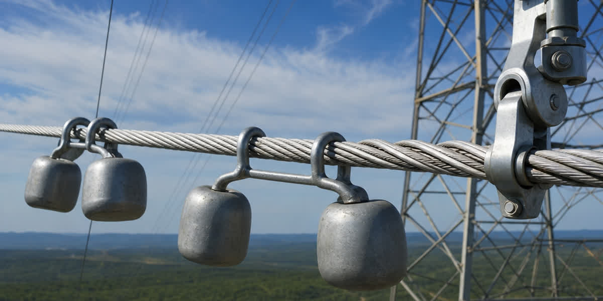
The Stockbridge damper is the world's most widely utilized device for controlling Aeolian vibration on power conductors and shield wires. Developed by George H. Stockbridge and advanced through decades of dynamic modeling, modern units feature: - Asymmetric Bell-Shaped Weights: Two slotted weights of differing masses and moments of inertia attached to the ends of a stranded steel messenger cable. - Four Resonance Frequencies: By tuning the mass distributions and cantilever lengths on both sides of the central clamp, the damper provides 4 distinct mechanical resonance modes spanning 5 Hz to 60 Hz. - Inter-Strand Friction Dissipation: As the conductor vibrates, the weights oscillate out of phase. The flexing high-tensile 19-strand steel messenger wire dissipates mechanical energy directly as frictional heat (Pd).
Damper Location Sizing Equation: The damper must be installed at a distance x from the suspension clamp exit to ensure it falls near an anti-node (maximum velocity point) across the highest expected vibration frequencies:
x = 0.85 * (lambda_min / 2) = 0.85 * (1 / (2 * f_max)) * sqrt(T / m)
Where: - x = Distance from suspension clamp center or armor rod end to damper clamp center (m) - f_max = Maximum expected vortex frequency corresponding to maximum laminar wind velocity (v_max ≈ 7.0 m/s) - lambda_min = Minimum vibration wavelength at f_max
3.2 Preformed Helical Armour Rods (IEC 61284)
Preformed helical armour rods are manufactured from high-strength aluminum alloy or aluminum-clad steel wires factory-formed into a helix with an inside diameter smaller than the conductor OD. When hand-applied over the conductor at suspension points: 1. Dynamic Stress Attenuation: Increases the composite section modulus (Z) at the suspension clamp mouth, reducing dynamic cyclic bending strains by 40% to 60%. 2. Fretting Isolation: Sacrificially absorbs clamping contact pressures and fretting micro-slip, ensuring the primary conductor strands remain pristine. 3. Flashover Thermal Buffer: Provides an additional thermal and mechanical buffer against electrical power arcs and lightning strikes.
3.3 Spiral Vibration Dampers (SVD) for Distribution and OPGW
For smaller diameter conductors (d < 19 mm), single-core service conductors, and OPGW/ADSS fiber optic cables where messenger-weight dampers might create concentrated clamping stress, Spiral Vibration Dampers (SVD) fabricated from solid weather-resistant polyvinyl chloride (PVC) are preferred. - Working Mechanism: The larger damping section coils loosely around the conductor. During Aeolian vibration, the conductor impacts the inner walls of the plastic helix, converting vibrational kinetic energy into impact and friction damping. - Interference Section: A tightly gripped spiral tail secures the SVD firmly to the conductor without metallic clamping hardware.
3.4 Spacer Dampers for Bundled Phase Conductors (IEC 61854)
In Extra-High-Voltage (EHV: 220kV - 500kV) and Ultra-High-Voltage (UHV: 750kV - 1100kV) lines with 2, 4, 6, or 8 bundled conductors per phase, subspan oscillation becomes a severe threat. Leeward conductors caught in the aerodynamic wake of windward sub-conductors experience periodic horizontal elliptical oscillations. - Spacer Dampers combine rigid structural geometry with high-damping elastomeric rubber articulation joints at each conductor clamp. - The engineered rubber bushings absorb both high-frequency Aeolian vibration energy and low-frequency subspan kinetic energy, while maintaining strict phase sub-conductor geometry under short-circuit electromagnetic pinch forces.
4. Hardware Selection and Damping Quantity Matrix
The table below outlines standard engineering recommendations for damping hardware configurations based on span length, terrain roughness, and conductor type:
| Span Length Range (L) | Terrain Exposure Category | Conductor Family | Recommended Hardware Configuration | Typical Damper Count per Span |
|---|---|---|---|---|
| Short (< 250 m) | Built-up / Forested (High turbulence) | AAC / AAAC / ACSR | Helical Armour Rods only (if EDS < 18%) | 0 (Self-damping sufficient) |
| Standard (250 - 500 m) | Open flat terrain / Agricultural | ACSR / ACAR | Helical Armour Rods + 4-Resonance Stockbridge Damper | 1 damper at each span end (2 per span) |
| Standard (250 - 500 m) | Coastal / Lake Shore / Desert | AAAC / OPGW | Armour Grip Suspension (AGS) + Stockbridge Dampers | 1 or 2 dampers per end (2-4 per span) |
| Long Span (500 - 1000 m) | River / Valley / Estuary Crossing | High-Tension ACSR / ACSS | Helical Armour Rods + Asymmetric Dual-Damper Systems | 2 to 3 dampers per end (4-6 per span) |
| Bundled EHV (300 - 600 m) | Open plains / Mountain passes | 2/4-Bundle ACSR / AAAC | Articulated Spacer Dampers with optimized subspan spacing | 1 spacer damper every 40 - 65 m |
5. Engineering Case Study: 220kV River Crossing Line Hardening
5.1 Project Background and Failure Diagnosis
A utility in Southeast Asia experienced recurrent broken aluminum strands on an 820-meter river crossing span utilizing 400/50 mm2 ACSR conductor operating at an Everyday Tension (EDS) of 24.5% RTS (H/w = 1780 m). - Inspection Findings: Severe fretting notch failures on the outer layer aluminum wires directly beneath the rigid trunnion suspension clamp. - Root Cause: Steady laminar wind off the river water surface (v = 2.5 - 4.5 m/s) induced relentless 28 Hz - 42 Hz Aeolian vibrations. The line lacked armour rods, and the original single damper had suffered messenger cable fatigue due to incorrect positioning (x = 2.4 m vs theoretical node of 1.35 m).
5.2 Engineered Solution and Post-Installation Results
- Conductor Replacement: Re-strung with high-precision ACSR conductor manufactured by Zhengzhou Sitong Cable Co., Ltd. with tight layer-pitch tolerances to maximize internal friction.
- Suspension Upgrade: Installed preformed aluminum alloy Helical Armour Rods (1800 mm length) paired with elastomer-cushioned Armour Grip Suspension (AGS) units to eliminate rigid metal-to-metal clamping.
- Dual Stockbridge Damping: Installed two multi-resonance Stockbridge dampers per span end at calculated positions (x1 = 1.15 m, x2 = 2.45 m) tuned to 12 Hz - 55 Hz.
- Field Validation: Real-time optical bending amplitude sensors installed 89 mm from the clamp confirmed that dynamic micro-strain dropped from 340 micro-strain to 78 micro-strain, well below the 150 micro-strain IEEE fatigue boundary. Zero strand failures have been recorded over 4 years of continuous operation.
6. Installation Best Practices and Quality Control
Achieving reliable line damping performance requires stringent quality adherence during construction:
- Torque Control on Damper Clamps: Damper clamp bolts must be torqued precisely to manufacturer specification (typically 40 - 45 N*m for aluminum conductor clamps). Under-torquing allows the damper to slip into a vibration node; over-torquing crushes outer conductor strands. Always use calibrated torque wrenches or breakaway shear-nut hardware.
- Armour Rod Centering: Helical armour rods must be centered exactly within the suspension clamp body with equal protrusion on both sides. Individual rod ends must snap fully into place without crossing, kinking, or leaving loose flaring wires.
- Vertical Alignment: Stockbridge damper weights must hang vertically plumb below the conductor. Slanted or tilted dampers create torsional harmonic coupling, reducing damping efficiency by up to 35%.
- No Direct Clamping on Bare Conductor in Heavy Damping Regimes: When dual dampers are installed, the second damper must be clamped directly over a dedicated helical protector strip or extended armour rod to prevent localized fatigue beneath the damper clamp.
7. Frequently Asked Questions (FAQ)
Q1: What is the primary difference between Aeolian vibration and conductor galloping?
Aeolian vibration is a high-frequency (3-120 Hz), low-amplitude (< 1 conductor diameter) oscillation caused by mild, laminar wind (1-7 m/s) shedding vortices across circular conductors. Conductor galloping is a low-frequency (0.1-1 Hz), extremely high-amplitude (up to several meters) vertical oscillation caused by moderate-to-strong winds (6-25 m/s) acting on aerodynamically unsymmetrical ice-coated conductors.
Q2: Why are AAAC conductors more susceptible to fatigue than ACSR at high tension?
AAAC conductor consists entirely of heat-treated aluminum-magnesium-silicon (6201-T81) alloy wires. While stronger than 1350 aluminum, the alloy has higher notch sensitivity and lower structural self-damping. In contrast, ACSR conductor features a high-strength galvanized steel core that carries the static tension while the outer aluminum layers carry the current, providing superior multi-material boundary friction damping.
Q3: How do preformed helical armour rods reduce bending stress at suspension clamps?
Preformed armour rods form a tightly wrapped sacrificial sleeve around the conductor, significantly increasing the effective moment of inertia and bending stiffness at the clamp entrance. This redistributes the sharp, localized peak bending strain across a broad 1.5-2.0 meter radius, reducing peak dynamic stresses at the clamp mouth by 40% to 60%.
Q4: Can Stockbridge dampers be used on OPGW fiber optic cables?
Yes, but specialized OPGW Stockbridge dampers or Spiral Vibration Dampers (SVD) must be selected. OPGW dampers feature precision-machined aluminum alloy clamps with smooth, radiused clamping profiles and torque-limiting shear bolts to prevent radial crushing forces that could deform the stainless steel optical fiber buffer tubes inside the OPGW cable.
Q5: How is the exact damper installation distance determined on a transmission span?
The installation distance is calculated from the minimum expected vibration half-wavelength (lambda_min = (1 / (2 * f_max)) * sqrt(T/m)). The damper is placed at x = 0.85 * (lambda_min / 2) from the clamp center or armour rod tip. This positions the damper within the active anti-node zone across the entire high-frequency operational spectrum, maximizing kinetic energy absorption.
8. Summary and Engineering Support
Effective Aeolian vibration protection requires balancing conductor stringing tension (% RTS) with advanced damping systems. Zhengzhou Sitong Cable Co., Ltd. (SiTong Cable) supplies fully tested, high-precision overhead conductors—including ACSR, AAAC, AAC, ACAR, and OPGW—manufactured in strict compliance with ASTM, IEC, BS, DIN, and AS/NZS standards, complete with matching preformed transmission fittings and hardware.
👉 Browse our complete ACSR Conductor Product Range 👉 Browse our Transmission Line Fittings and Hardware Range 👉 Contact our Transmission Engineering Support Team
📬 Sales inquiries: sales@sitongcable.com | 📞 Phone: +86-371-69176007