Commercial EV Fast-Charging Hub Power Infrastructure: Grid Connection, MV/LV Feeder Sizing, Underground Trenching & IEC 60364-7-722 / NEC 625 Engineering Guide
Commercial EV Fast-Charging Hub Power Infrastructure: Grid Connection, MV/LV Feeder Sizing, Underground Trenching & IEC 60364-7-722 / NEC 625 Engineering Guide
Commercial EV fast-charging plazas and heavy-duty fleet electrification hubs require robust medium- and low-voltage distribution infrastructure to withstand extreme duty cycles, severe harmonic distortion, and high coincidence factors. This comprehensive engineering guide examines primary grid interconnection, MV and LV cable sizing, duct bank thermal derating, grounding grid design, and termination reliability under IEC 60364-7-722 and NEC Article 625 standards.
1. Introduction: The Unique Electrical Demands of EV Charging Hubs
The global acceleration of commercial electric vehicle (EV) adoption—spanning passenger vehicle highway charging plazas, municipal transit bus depots, and logistics fleet electrification—has fundamentally altered the design paradigms of medium-voltage (MV) and low-voltage (LV) electrical distribution networks. Unlike conventional commercial facilities (such as office parks, retail centers, or light industrial manufacturing) where load diversity factors typically range from 0.40 to 0.65, high-power DC fast-charging (DCFC) hubs operate with coincidence factors often exceeding 0.85 to 1.00 during peak operational windows.
Modern charging hubs deploy High-Power Charging (HPC) dispensers operating at 150 kW to 400 kW per stall, while upcoming commercial vehicle corridors are adopting Megawatt Charging Systems (MCS) capable of delivering up to 1.2 MW to 3.75 MW at 1,250 V DC. When multiple charging units are aggregated on a common bus, the power delivery infrastructure faces severe technical challenges: - Continuous Thermal Loading: In accordance with NEC 625.42 and IEC 61851-1, EV charging loads are classified as continuous duty (operating at maximum rated load for 3 hours or more). Consequently, branch circuits and feeder conductors must be sized at 125% of continuous rated capacity before applying environmental derating. - Extreme Harmonic Heating: Solid-state AC-DC active front-end (AFE) or diode/thyristor bridge rectifiers inject significant harmonic currents (predominantly 5th, 7th, 11th, and 13th orders in 6-pulse or 12-pulse configurations, alongside high-frequency switching harmonics from IGBT stages). These harmonics increase conductor AC resistance via the skin effect and proximity effect, elevating conductor operating temperatures well above fundamental frequency calculations. - Cyclic Thermal Fatigue in Duct Banks: Rapid ramping between idle and full charging power creates severe thermal cycling, stressing cable insulation compounds, lead/aluminum moisture sheaths, and concrete-encased duct systems. - Strict Voltage Regulation: Fast-charging power conversion modules require stable input AC voltage ($\pm 5\%$ nominal, with maximum steady-state voltage drop $\le 2.0\%$ across LV distribution feeders) to prevent rectifier tripping and dc-link instability.
To build resilient, cost-effective infrastructure, electrical engineers and EPC contractors must specify certified, high-reliability cable systems from trusted manufacturers. SiTong Cable provides comprehensive cable solutions engineered specifically to withstand the rigorous demands of utility-scale charging infrastructure.
2. Power Architecture & Grid Interconnection Topology
The electrical architecture of an EV charging plaza depends directly on the total connected nameplate capacity and the available utility Point of Common Coupling (PCC).
[ Utility 11kV - 33kV Grid ]
             │
   (MV Underground Cable: XLPE / SWA or AWA)
             │
             ▼
[ Dedicated Pad-Mounted Substation / Transformer ]
   11kV/33kV Step-Down to 400V (IEC) or 480V (NEC)
             │
             ├────────────────────────────────────────┐
             │ (LV Heavy Feeders: XLPE / SWA / URD)   │ (Auxiliary & BESS Feeder)
             ▼                                        ▼
   [ Central Power Cabinets ]               [ Battery Energy Storage (BESS) ]
   (AC-DC Rectifier Stack)                            │
             │                                        │
             │ (Liquid-Cooled DC Cables & Control)    │
             ▼                                        │
   [ Dispenser Stalls / HPC Posts ] ◄─────────────────┘
Table 1: EV Charging Hub Classification & Feeder Specifications
| Charging Class | Power per Dispenser | Input Voltage Architecture | Typical Hub Configuration | Primary Feeder Requirement | Target Power Factor / THD-i |
|---|---|---|---|---|---|
| Level 2 AC Fleet Depot | 7.2 kW – 22 kW | 208V / 240V / 400V 3-Phase AC | 20–100 overnight fleet stalls | Multi-core copper/aluminum building wire or LV underground cable | PF > 0.95, THD-i < 10% |
| DC Fast Charging (DCFC) | 50 kW – 150 kW | 400V / 480V 3-Phase AC | 4–12 public highway dispensers | Heavy LV copper/aluminum XLPE insulated power cables | PF > 0.98, THD-i < 5% |
| High Power Charging (HPC) | 200 kW – 400 kW | 400V / 480V AC (or direct MV step-down) | 8–24 highway corridor chargers | Parallel runs of 400–630 mm² LV SWA or single-core AWA | PF > 0.99, THD-i < 3% |
| Megawatt Charging (MCS) | 1.0 MW – 3.75 MW | Dedicated 11kV / 22kV / 33kV Primary Substation | 2–8 heavy electric truck bays | Primary MV XLPE cables feeding dedicated local transformers | Dedicated active harmonic filtration required |
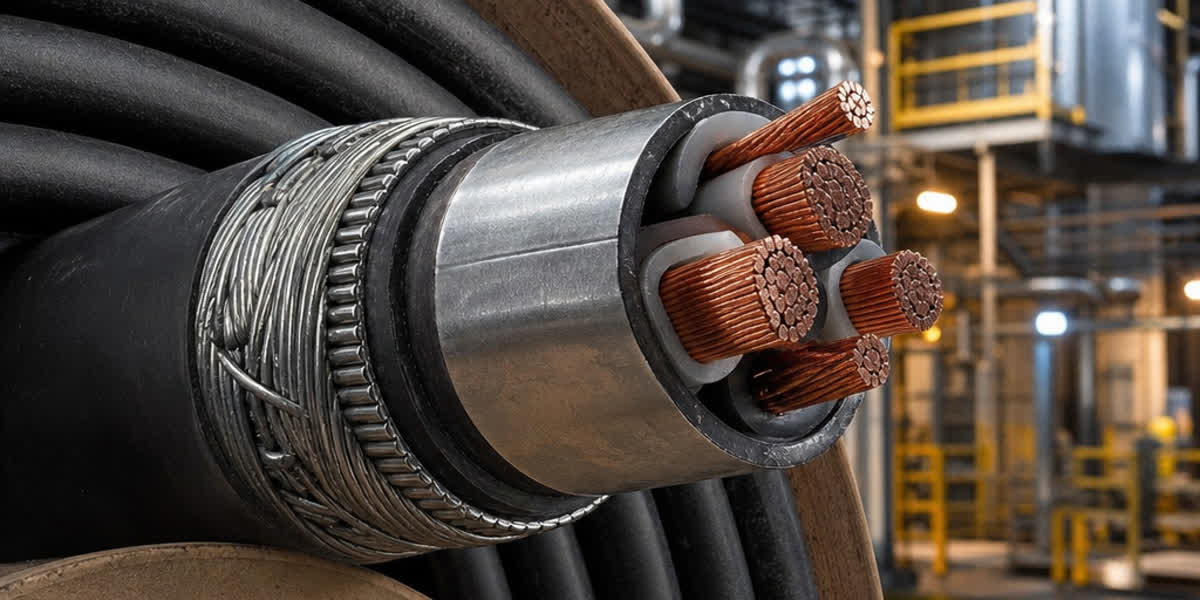
For charging hubs with total aggregate capacity exceeding 1.5 MVA to 2.0 MVA, utilities generally mandate a dedicated medium-voltage service connection at 11 kV, 20 kV, 22 kV, or 33 kV. Specifying high-grade power cable assemblies—specifically triple-extruded, tree-retardant XLPE (TR-XLPE) insulated cables with copper tape or copper wire screen and galvanized steel wire armour (SWA)—is essential to ensure zero dielectric breakdown and long-term operating life under fluctuating grid conditions.
3. Medium-Voltage (MV) and Low-Voltage (LV) Feeder Sizing Methodology
Feeder sizing for EV charging hubs cannot rely solely on standard tabular ampacities found in general electrical codes. A rigorous multi-step engineering methodology is required:
3.1 Continuous Duty and Coincidence Factor Application
Under NEC Article 625.42 and IEC 60364-7-722.311, the total design current $I_{\text{design}}$ must be calculated based on the aggregate charging capacity with an allowance for continuous operation:
$$I_{\text{design}} = \frac{\sum (P_i \times k_{\text{coincidence}})}{\sqrt{3} \times V_{\text{line}} \times \cos\phi \times \eta} \times 1.25$$
Where: - $P_i$ = Nameplate rating of charging station $i$ (kW) - $k_{\text{coincidence}}$ = Diversity/coincidence factor (typically 1.0 for hubs with $\le 4$ chargers, 0.85–0.90 for hubs with 5–15 chargers, and 0.80 for fleet depots with dynamic load balancing) - $V_{\text{line}}$ = Nominal line-to-line AC voltage (e.g., 400 V or 480 V) - $\cos\phi$ = Operating displacement power factor ($\ge 0.98$ for modern active front-end converters) - $\eta$ = Converter operating efficiency (typically 0.94 to 0.96) - $1.25$ = 125% continuous load safety factor (NEC 625.42 / IEC requirement for continuous maximum load $\ge 3$ hours)
3.2 Thermal Ampacity Derating Formulations
The effective current-carrying capacity $I_{\text{effective}}$ of underground feeder conductors installed in trenches or concrete duct banks must satisfy:
$$I_{\text{effective}} = I_{\text{base}} \times k_{\text{temp}} \times k_{\text{group}} \times k_{\text{depth}} \times k_{\text{soil}}$$
- $k_{\text{temp}}$: Ambient ground temperature correction factor (base $20^\circ\text{C}$ for IEC 60287, or base $30^\circ\text{C}$ for NEC Table 310.16). In hot summer periods with ambient ground temperatures reaching $30^\circ\text{C}$ to $35^\circ\text{C}$ at burial depth, $k_{\text{temp}}$ drops to 0.89–0.93 for 90°C XLPE insulation.
- $k_{\text{group}}$: Proximity derating factor for grouped parallel conduit runs. In an 8-way or 12-way duct bank, $k_{\text{group}}$ can drop as low as 0.52 to 0.65.
- $k_{\text{depth}}$: Burial depth derating factor for depths exceeding standard installation depth (1.0 m to 1.5 m).
- $k_{\text{soil}}$: Soil thermal resistivity correction factor ($g$ or $\rho$). Standard tables assume $\rho = 1.0 \text{ K}\cdot\text{m/W}$. In dry, sandy soils or uncompacted native backfill, $\rho$ frequently climbs to $1.8 - 2.5 \text{ K}\cdot\text{m/W}$, forcing a derating of 25% to 35%.
For these challenging underground runs, installing heavy-duty copper or aluminum underground cable manufactured with cross-linked polyethylene (XLPE) insulation rated for 90°C continuous operation and 250°C short-circuit withstand provides the necessary thermal headroom.
   TYPICAL 8-WAY CONCRETE-ENCASED DUCT BANK (CROSS-SECTION)
   ════════════════════════════════════════════════════════
                  Finished Ground Level (Grade)
   ────────────────────────────────────────────────────────
                              │
                    Depth to top: ≥ 750 mm
                              │
               ┌─────────────────────────────┐
               │    Red Concrete Marker Cap  │
               │   (Warning Tape Embedded)   │
               ├─────────────────────────────┤
               │   [○]      [○]      [○]    │  ◄── Spacer: 75mm min.
               │   Duct 1   Duct 2   Duct 3  │      Fluidized Thermal
               │                             │      Backfill (FTB)
               │   [○]      [○]      [○]    │      ρ ≤ 1.0 K·m/W
               │   Duct 4   Duct 5   Duct 6  │
               │                             │
               │   [○]               [○]    │
               │   Spare 1           Spare 2 │
               └─────────────────────────────┘
3.3 Voltage Drop Constraints
Because fast-charger AC-DC power modules are sensitive to supply under-voltage, total voltage drop from the pad-mounted distribution transformer to the charger power cabinet must not exceed 2.0% at peak rated continuous current. The three-phase voltage drop is verified using:
$$\Delta V = \sqrt{3} \times I_{\text{design}} \times L \times (R \cos\phi + X \sin\phi)$$
Where $L$ is the one-way circuit length (km), $R$ is the AC resistance of the conductor at operating temperature (90°C) taking skin and proximity effects into account ($\Omega/\text{km}$), and $X$ is the inductive reactance of the cable formation ($\Omega/\text{km}$).
Table 2: Conductor Engineering Sizing for EV Fast Charging Feeders (400V/480V 3-Phase AC)
| Total Charger Power (kW) | Input Current @ 480V (A) | Min. Design Ampacity (125% Rule) | Recommended Copper Conductor (XLPE) | Recommended Aluminum Conductor (XLPE) | Max. Run Length for $\le 2\%$ Voltage Drop |
|---|---|---|---|---|---|
| 50 kW | 60.1 A | 75.2 A | 16 mm² (4 AWG) Cu | 25 mm² (2 AWG) Al | 68 m |
| 150 kW | 180.4 A | 225.5 A | 95 mm² (3/0 AWG) Cu | 150 mm² (250 kcmil) Al | 48 m |
| 300 kW | 360.8 A | 451.0 A | 240 mm² (500 kcmil) Cu | 400 mm² (750 kcmil) Al | 42 m |
| 350 kW | 421.0 A | 526.3 A | 300 mm² (600 kcmil) Cu or 2x 120 mm² Cu | 500 mm² (1000 kcmil) Al or 2x 185 mm² Al | 38 m |
| 500 kW (Dual Stall) | 601.4 A | 751.8 A | 2x 240 mm² (2x 500 kcmil) Cu | 2x 400 mm² (2x 750 kcmil) Al | 45 m |
| 1000 kW (Hub Feeder) | 1202.8 A | 1503.5 A | 4x 240 mm² (4x 500 kcmil) Cu | 4x 400 mm² (4x 750 kcmil) Al | 40 m |
4. Underground Trenching, Duct Banks & Thermal Backfill Physics
The physical civil installation of underground power cables dictates the real-world ampacity and life expectancy of an EV charging hub. The heat generated within the cables ($I^2 R$) must dissipate through the insulation, outer sheath, conduit wall, and surrounding earth.
4.1 Neher-McGrath & IEC 60287 Thermal Dissipation
The thermal resistance network per IEC 60287 consists of internal cable thermal resistance ($T_1, T_2, T_3$) and external ground thermal resistance ($T_4$). When multiple conduit runs are grouped tightly together in a trench, mutual thermal proximity causes heat traps: - In direct-buried installations, thermal runaway occurs if dry-out of soil around the cable occurs due to sustained high cable surface temperatures ($> 50^\circ\text{C}$). Soil moisture migrates away from the heat source, increasing local soil resistivity from $1.0 \text{ K}\cdot\text{m/W}$ to over $3.0 \text{ K}\cdot\text{m/W}$. - To prevent thermal dry-out, engineers specify Fluidized Thermal Backfill (FTB)—a mix of sand, cement, fly ash, and water engineered to guarantee a maximum cured thermal resistivity of $\rho \le 1.0 \text{ K}\cdot\text{m/W}$ under zero-moisture conditions.
4.2 Conduit Selection & Mechanical Protection
Conduits housing power cables must be evaluated for mechanical crush resistance and ease of pulling: - Rigid Nonmetallic Conduit (PVC Schedule 40/80): Excellent corrosion resistance, standard for concrete encasement. - High-Density Polyethylene (HDPE) Smoothwall: Preferred for Horizontal Directional Drilling (HDD) under paved parking areas to avoid tearing up existing asphalt. - Mechanical protection is critical: where cables enter transformer pads or charging posts, stainless steel or aluminum cable cleats must be deployed to restrain conductors against dynamic short-circuit electromagnetic forces. Engineers must specify properly rated cable support components from dedicated fittings & hardware catalogs to maintain formation under fault conditions.
5. Grounding Grid Design, Equipotential Bonding & Safety Standards
Grounding in high-power EV charging plazas is an essential life-safety and functional protection discipline. Because EV drivers handle charging connectors in outdoor, exposed public environments (often in rainy or wet conditions), touch voltages on exposed conductive parts of charging equipment must strictly remain below $50\text{ V AC}$ (under normal conditions) and below $25\text{ V AC}$ (in wet environments per IEC 60364-7-722).
   EV CHARGING STATION EQUIPOTENTIAL GROUNDING SYSTEM
   ═════════════════════════════════════════════════
          [ 400V/480V Charger Kiosk ]
            │                     │
      (Equipment Grounding   (Enclosure Frame
        Conductor - EGC)      Bonding Conductor)
            │                     │
            └──────────┬──────────┘
                       │ Exothermic Weld / Heavy Compression Lug
                       ▼
   ────────────────────┬───────────────────────────── Finished Grade
                       │
       ┌───────────────┴─────────────────┐
       │   Earth Ground Loop / Grid       │
       │   Depth: ≥ 600 mm below grade   │
       │                                 │
       ▼                                 ▼
   [ Ground Rod 1 ]              [ Ground Rod 2 ]
   (Copper-Clad Steel)           (Copper-Clad Steel)
       │                                 │
       └─────────────────────────────────┘
          Interconnected via [Galvanized Steel Wire](/products/?first_category=bare_conductor&second_category=galvanized_steel_wire)
          or Bare Stranded Copper Conductor (IEEE 80 / IEC 62561)
5.1 PEN Conductor Fault Protection (TN-C-S / PME Networks)
In regions utilizing TN-C-S (Protective Multiple Earthing - PME) distribution networks, a break in the upstream combined Protective Earth and Neutral (PEN) conductor can cause the exposed metallic chassis of the vehicle and charging station to rise to dangerous phase-to-ground potentials. IEC 60364-7-722 stipulates three protective compliance pathways: 1. Dedicated Earth Electrode (TT Islanding): The EV charging station earthing system is completely separated from the PME supply earth and connected to a dedicated low-resistance earth electrode ($R_E < 20\,\Omega$). 2. Voltage-Monitored Disconnection Devices: Automatic disconnection of phase, neutral, and earth conductors within 5 seconds if the potential difference between the protective earth and true ground exceeds $70\text{ V RMS}$. 3. Equipotential Earth Mesh: Installing a bare buried ground mat directly beneath the vehicle parking bay and charging dispenser.
To build an enduring underground earth mesh with high mechanical pull-strength and superior resistance to electrolytic and soil galvanic corrosion, engineers frequently specify heavy-gauge galvanized steel wire strand or bare copper conductors conforming to ASTM A475 and IEC 60888 standards.
6. Auxiliary Power, Control Cabling & High-Current Terminations
Beyond primary power delivery, an EV fast-charging hub incorporates extensive auxiliary subsystems that require dedicated cabling disciplines:
6.1 Auxiliary Subsystems & Building Wire
Pad-mounted transformers, switchgear control power, credit-card payment kiosks, security lighting, CCTV surveillance, and Battery Energy Storage Systems (BESS) require stable single-phase and three-phase auxiliary distribution. High-grade electric wire such as THHN/THWN-2 (PVC/Nylon) or XHHW-2 (XLPE insulated, water-resistant) ensures reliable subpanel wiring under harsh ambient thermal conditions. For utility service entrance transitions to administrative kiosks or metering panels, single-phase or three-phase concentric cable (SEU/SER) provides compact, tamper-proof, and anti-theft power routing.
6.2 Communications & Dynamic Load Management
Modern charging hubs employ sophisticated Dynamic Load Balancing (DLB) and Open Charge Point Protocol (OCPP) communication systems to throttle charging outputs in real time, preventing grid transformer overload. Because these data lines run in parallel with high-current AC and DC power conductors emitting substantial electromagnetic fields (EMF), signal cables must be shielded against capacitive and inductive interference. Installing multi-pair, aluminum-foil and tinned-copper-braid shielded control cable prevents data frame corruption, communication drops, and metering anomalies.
6.3 Termination Integrity: Preventing Aluminum Creep and Thermal Runaway
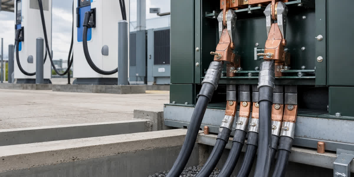
Due to the cyclic heating and cooling of fast-charger feeders, cable terminations represent the single highest failure point in field installations: - When aluminum conductors are connected directly to copper or tin-plated copper busbars inside charger power cabinets, differential thermal expansion coefficients can loosen mechanical connections over time. - Furthermore, galvanic corrosion occurs when atmospheric moisture creates an electrolyte bridge between dissimilar metals. - To eliminate this failure mode, engineers must mandate certified bimetallic friction-welded cable lugs or shear-bolt mechanical connectors. These components feature pre-greased barrels with oxide-inhibiting compound and torque-limiting shear heads that guarantee factory-specified contact pressure regardless of installer tool calibration.
7. Comparative Technical Overview of EV Hub Cabling
Table 3: Cable Selection Guide Across EV Charging Infrastructure Subsystems
| Subsystem | Operating Voltage / Signal | Recommended Conductor Material | Recommended Insulation & Sheath | Applicable Standards | Key Performance Requirement |
|---|---|---|---|---|---|
| Primary Grid Interconnection | 11 kV – 33 kV AC | Stranded Copper or AA-8000 Aluminum | TR-XLPE / Copper Wire Screen / SWA / PE or PVC Sheath | IEC 60502-2, BS 6622, ICEA S-94-649 | High impulse withstand, water-tree resistance, mechanical crush protection |
| LV Transformer to Power Cabinet | 400 V – 480 V AC | High-purity Copper or Aluminum | XLPE / SWA or Direct Burial URD | IEC 60502-1, BS 5467, UL 44 / UL 1277 | Continuous 90°C rating, 125% ampacity sizing, low voltage drop |
| Earth Grounding Grid & Mesh | Fault / Lightning Current | Bare Copper or Galvanized Steel Strand | Bare (Uninsulated) | IEEE 80, IEC 62561, ASTM A475, BS 183 | High short-circuit thermal capacity, corrosion resistance in soil |
| Station Auxiliary & Metering | 120V / 240V / 400V AC | Annealed Copper / AA-8000 Aluminum | PVC/Nylon (THHN) or XLPE (XHHW-2 / Concentric) | UL 83, UL 44, NEC Article 338 | Flame retardance, oil/gasoline resistance, tamper-proof |
| OCPP & Dynamic Load Balancing | RS-485 / CAN / Ethernet | Tinned Annealed Copper (Stranded) | XLPE/PE Insulation, Overall Foil + Tinned Copper Braid Shield, LSZH | EN 50288-7, BS 5308, IEC 60332-1 | High noise immunity (EMC), low transfer impedance |
8. Frequently Asked Questions (FAQ)
Q1: Why must EV charging feeder cables be sized at 125% of maximum rated current?
A: Under both NEC Article 625.42 and IEC 61851-1, electric vehicle charging loads are legally classified as continuous duty, meaning the equipment operates at full rated current for 3 hours or more during standard charging cycles. Sizing conductors at 125% ensures that internal heat generation reaches a stable equilibrium without exceeding the cable's maximum operating temperature rating (typically 90°C for XLPE). Sizing without this 25% safety margin accelerates thermal aging of the insulation and increases the risk of premature dielectric breakdown.
Q2: What is the optimal cable choice between copper and aluminum conductors for EV charging hubs?
A: Both conductor materials are viable when engineered properly. High-conductivity electrolytic copper conductors offer smaller overall cable diameters, lower bend radii, and smaller conduit requirements, making them ideal for tight terminal compartments inside compact charger dispensers. However, for long underground feeders between the substation transformer and central power cabinets, AA-8000 series aluminum alloy conductors provide a 40% to 50% savings in raw material cost and weigh significantly less, easing cable pulling. When aluminum is specified, engineers must use bimetallic cable lugs with torque-limiting shear bolts to eliminate thermal creep and galvanic corrosion at copper busbars.
Q3: How do harmonic currents generated by fast chargers affect cable selection?
A: Modern fast chargers utilize active front-end (AFE) PWM rectifiers with high switching frequencies alongside harmonic components. These non-sinusoidal currents increase conductor AC resistance via skin and proximity effects. In multi-conductor feeders or paralleled single-core runs, harmonic currents cause unexpected heating in phase conductors and can induce substantial circulating currents in neutral conductors and metallic sheaths. Engineers must specify cables with high-grade XLPE insulation rated for 90°C continuous operation and verify that neutral conductors are sized at 100% to 200% of phase rating if triplen harmonics (3rd, 9th, 15th) are present.
Q4: What are the primary installation causes of cable failure in EV charging duct banks?
A: The top three root causes of underground cable failures in charging plazas are: 1. Soil Thermal Dry-out: Poor native backfill with high thermal resistivity ($\rho > 2.0 \text{ K}\cdot\text{m/W}$) traps heat, causing moisture to migrate away and triggering thermal runaway. 2. Excessive Pulling Tension or Sidewall Pressure: Exceeding manufacturer maximum pulling tension or bending radius limits during installation through tight 90-degree sweeps damages the outer jacket and XLPE insulation. 3. Substandard Terminations: Inadequate torque on terminal lugs or omission of oxide-inhibiting paste on aluminum connections causes localized overheating, leading to melted terminal blocks and equipment fires.
Q5: Can standard building wire (like THHN) be used for outdoor underground EV charger feeders?
A: Standard dry-rated building wire must never be installed directly in underground conduits without water-resistant ratings. Conduits installed underground are classified as "wet locations" by electrical codes because condensation and ground water ingress inevitably occur. Feeder conductors installed underground must carry dual wet-ratings, such as THWN-2, XHHW-2, or dedicated direct-burial armored underground cable with moisture-blocking radial barriers.
9. SiTong Cable: Certified Engineering Solutions for EV Charging Infrastructure
As a leading global manufacturer of electrical wire and cable solutions, Zhengzhou Sitong Cable Co., Ltd. (SiTong Cable) delivers end-to-end cable systems tailored for electric vehicle charging infrastructure, utility grid interconnections, and industrial power distribution:
- Comprehensive Manufacturing Capabilities: Operating automated continuous vulcanization (CCV) extrusion lines, advanced tandem wire-drawing systems, and automated high-speed armouring machines, SiTong Cable manufactures medium-voltage power cables (up to 35 kV), low-voltage armored and unarmored distribution cables, bare grounding conductors, and specialized instrumentation cables.
- Strict Quality Assurance & Testing: Every production drum undergoes rigorous factory routine and sample testing in accordance with IEC 60502, ASTM B232, BS 5467, and ICEA standards, including partial discharge testing ($< 5\text{ pC}$ at $1.73 U_0$), AC voltage withstand testing, conductor DC resistance measurement, and insulation elongation checks.
- Global Project Track Record: SiTong Cable products have been deployed across public utility grids, solar PV generation facilities, mining complexes, and municipal transport infrastructure across more than 80 countries in Southeast Asia, the Middle East, Africa, Europe, and the Americas.
- Custom Engineering Support: We provide project-specific drum length optimization to minimize underground splice joints, pre-engineered cable cleat and lug packages, and comprehensive thermal ampacity calculations tailored to your site's specific soil resistivity and conduit configurations.
Related Engineering Resources & Technical Inquiries
👉 Browse our medium and low voltage power cable range 👉 Battery Energy Storage System (BESS) Cable Sizing and Engineering Guide 👉 Contact our engineering team for technical sizing and project quotations
📬 Sales inquiries: sales@sitongcable.com | 📞 Phone: +86-371-69176007