Rubber Welding Cable (H01N2-D and H01N2-E): Engineering Sizing, Duty Cycle Sizing, Flex Life and Harsh Environment Standards (IEC 60245-6, EN 50525-2-81, UL 1276)
Rubber Welding Cable (H01N2-D and H01N2-E): Engineering Sizing, Duty Cycle Sizing, Flex Life and Harsh Environment Standards (IEC 60245-6, EN 50525-2-81, UL 1276)
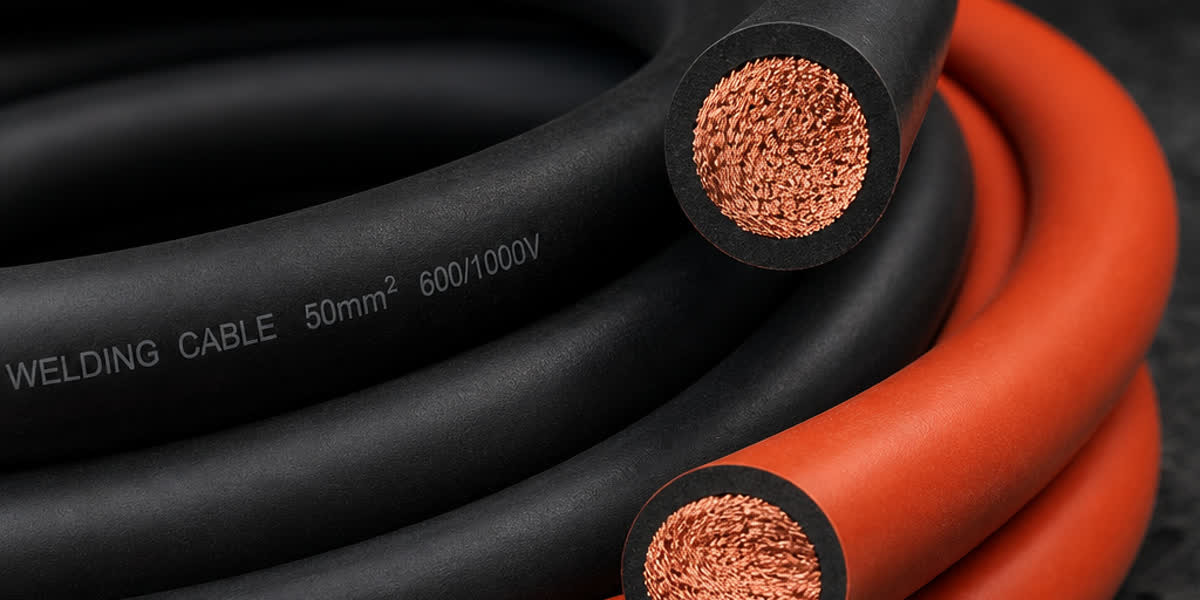
Rubber welding cable is a specialized, ultra-flexible single-conductor elastomer power cable engineered to transmit high-current electrical power between secondary welding power sources, electrode holders, and automatic or manual welding tools under severe mechanical and thermal stress. Operating under intense duty cycles and harsh industrial conditions, these cables demand exceptional dynamic flexibility, thermal endurance up to 85°C or 90°C, and chemical resilience against hot weld spatter, ozone, mineral oils, and continuous flexing. Governed by international standards including IEC 60245-6, EN 50525-2-81, and UL 1276, optimal cable performance relies on precise duty cycle derating, strict loop voltage drop management, and premium elastomer compound formulations.
1. Conductor Architecture: Class 6 Super-Fine Copper Stranding Physics
The fundamental operational requirement of secondary welding cables is extreme mechanical flexibility combined with high torsional fatigue resistance. Unlike standard building wire or fixed installation industrial cables that utilize rigid Class 1 solid or Class 2 stranded conductors, high-performance welding cables employ Class 6 (or Class 5 in specific heavy-duty variants) extra-fine bare or tinned annealed electrolytic copper conductors in compliance with IEC 60228 and EN 60228.
Conductor Stranding Dynamics and Flexibility Classes
In heavy industrial fabrication yards and shipbuilding docks, welding leads undergo thousands of flexural cycles, sharp bend radiuses, and severe twisting per work shift. To achieve high mechanical suppleness without work-hardening the copper, manufacturers strand hundreds or thousands of microscopic oxygen-free copper wires into individual bunches, which are subsequently cabled together in a rope-lay concentric configuration.
- Class 6 Conductors (EN 60228 / IEC 60228): Feature individual strand diameters between 0.15 mm and 0.21 mm (approximately 34 AWG to 32 AWG). This ultra-fine stranding delivers superior pliability, minimal operator wrist fatigue in manual metal arc welding (SMAW/MMA), and extended fatigue life under dynamic bending.
- Class 5 Conductors (EN 60228 / IEC 60228): Utilize individual wire diameters between 0.25 mm and 0.41 mm (approximately 30 AWG). Class 5 provides robust flexibility suitable for machine interconnections, robotic track welding, and high-ampacity submerged arc welding (SAW) installations.
- UL 1276 Class K vs. Class M Stranding: In North American industrial engineering, UL 1276 recognizes Class K stranding (30 AWG / 0.25 mm strands) as standard flexibility and Class M stranding (34 AWG / 0.16 mm strands) as extra-flexible welding lead wire.
At Zhengzhou SiTong Cable Co., Ltd. (SiTong Cable), all flexible conductor cores are drawn from 99.99% high-purity electrolytic oxygen-free copper (OFC) rods. Our production facility pairs high-speed multi-wire bunching with computerized planetary stranding machinery to achieve optimal strand pitch, preventing bird-caging, internal wire shear, and focal localized heating during continuous current surges. Engineers and procurement teams can explore our complete Rubber Welding Cable & flexible electric wire range for detailed physical dimensions.
Technical Conductor Stranding and Resistance Specifications (IEC 60228 Class 6)
| Metric Size (mm²) | Equivalent AWG / kcmil | Typical Strand Construction (No. x mm) | Max Strand Diameter (mm) | Max DC Resistance at 20°C (Ω/km) | Nominal Outer Diameter (mm) | Approx. Cable Weight (kg/km) |
|---|---|---|---|---|---|---|
| 16 mm² | 6 AWG | ~510 x 0.20 | 0.21 | 1.210 | 8.8 - 10.5 | 205 |
| 25 mm² | 4 AWG | ~796 x 0.20 | 0.21 | 0.780 | 10.1 - 12.5 | 305 |
| 35 mm² | 2 AWG | ~1115 x 0.20 | 0.21 | 0.554 | 11.4 - 14.0 | 415 |
| 50 mm² | 1/0 AWG | ~1596 x 0.20 | 0.21 | 0.386 | 13.2 - 16.5 | 575 |
| 70 mm² | 2/0 AWG | ~2214 x 0.20 | 0.21 | 0.272 | 15.3 - 18.5 | 785 |
| 95 mm² | 3/0 AWG | ~3024 x 0.20 | 0.21 | 0.206 | 17.1 - 21.0 | 1030 |
| 120 mm² | 4/0 AWG | ~3819 x 0.20 | 0.21 | 0.161 | 19.2 - 23.5 | 1280 |
2. Elastomer Compound Chemistry: Dual-Layer vs. Single-Layer Sheathing
Welding cables face an aggressive operating environment that quickly destroys general-purpose thermoplastic compounds like PVC. Droplets of molten weld spatter (reaching temperatures exceeding 1000°C upon contact), dragging across jagged steel plates, exposure to petroleum lubricants, and intense UV radiation from welding electric arcs demand specialized cross-linked thermosetting elastomer compounds.
Elastomer Compound Formulations
Two primary structural configurations dominate modern welding cable manufacturing:
- Single-Layer Heavy-Duty Elastomer (Standard H01N2-D / UL 1276 Single Jacket): The conductor is wrapped in a non-hygroscopic polyester separator tape, followed by a single, monolithic extrusion of vulcanized synthetic elastomer (typically Chlorinated Polyethylene - CPE, or Polychloroprene - PCP/Neoprene). This compound simultaneously provides primary electrical dielectric strength and heavy mechanical abrasion resistance.
- Dual-Layer Composite Architecture (Insulated & Sheathed H01N2-E / Premium Industrial): Features a dedicated inner insulation layer of high-dielectric Ethylene Propylene Diene Monomer (EPDM / EPR) rubber, wrapped by an outer protective jacket of chloroprene or chlorosulfonated polyethylene (CSPE/Hypalon). This dual-layer construction delivers superior dielectric integrity, enhanced flexibility, and two-color wear-indication (e.g., orange outer sheath over black insulation), allowing safety inspectors to immediately detect outer jacket compromise before conductor exposure occurs.
Material Performance Comparison Matrix
| Property | Standard PVC (Thermoplastic) | EPDM / EPR Rubber (Thermoset) | Chloroprene / Neoprene (Thermoset) | Chlorinated Polyethylene (CPE) |
|---|---|---|---|---|
| Max Operating Temperature | 70°C | 90°C | 85°C - 90°C | 90°C - 105°C |
| Short-Circuit Withstand Temp | 160°C | 250°C | 200°C | 220°C |
| Low-Temperature Flexibility | -10°C (embrittles) | -40°C (flexible) | -30°C (flexible) | -35°C (flexible) |
| Weld Spatter & Slag Resistance | Poor (melts instantly) | Moderate | Excellent (self-extinguishing) | Excellent (high char yield) |
| Mineral Oil Resistance | Poor (swells/softens) | Poor to Fair | Excellent (IEC 60811-404) | Outstanding |
| Tear & Abrasion Resistance | Low | Moderate | High (≥ 15 N/mm) | Very High (≥ 18 N/mm) |
| Ozone & UV Arc Resistance | Moderate | Outstanding | Excellent | Outstanding |
To supply secondary welding systems reliably, plant designers must also ensure the primary mains power distribution is sized correctly. Facilities route high-reliability 400V/480V primary mains through rugged industrial power cable to feed multi-operator welding transformers and inverter power racks.
3. Duty Cycle Physics and Engineering Ampacity Calculations
A common engineering error in fabrication shops is sizing secondary welding cables according to continuous 100% steady-state ampacity ratings. Arc welding is inherently an intermittent cyclic process. Sizing a cable for continuous current when the operation runs at a 35% duty cycle leads to over-sized, unwieldy, and unnecessarily expensive cable runs. Conversely, underestimating duty cycle causes thermal insulation degradation, increased electrical resistance, and hazardous fire risks.
The Duty Cycle Formula
The duty cycle of a welding power source is defined as the percentage of time within an arbitrary 5-minute (IEC 60974-1) or 10-minute (NEMA / AWS) reference period that the machine can operate at its rated output current without exceeding thermal equilibrium limits:
$$\text{Duty Cycle (\%)} = \left( \frac{T_{\text{on}}}{T_{\text{on}} + T_{\text{off}}} \right) \times 100$$
To determine the permissible thermal current rating ($I_{\text{rated}}$) at any specific operational duty cycle ($D$), electrical engineers utilize the thermal integration formula derived from Joule heating ($I^2 t$ equivalence):
$$I_{\text{rated}} = I_{100\%} \times \sqrt{\frac{100}{D}}$$
Where: * $I_{100\%}$ = Permissible continuous current rating (100% duty cycle, e.g., automated continuous submerged arc welding). * $D$ = Desired operational duty cycle percentage (e.g., 60% for semi-automatic MIG/GMAW, 35% for manual stick SMAW).
Welding Cable Current-Carrying Capacity vs. Duty Cycle (Ambient Temp 30°C, Max Conductor Temp 85°C)
| Cable Size (mm²) | Equivalent AWG / kcmil | 100% Duty Cycle (Continuous / Auto SAW) | 85% Duty Cycle (Heavy Automatic MIG) | 60% Duty Cycle (Semi-Auto MIG/MAG) | 35% Duty Cycle (Manual SMAW / Stick) |
|---|---|---|---|---|---|
| 16 mm² | 6 AWG | 135 A | 145 A | 175 A | 230 A |
| 25 mm² | 4 AWG | 180 A | 195 A | 230 A | 300 A |
| 35 mm² | 2 AWG | 225 A | 245 A | 290 A | 380 A |
| 50 mm² | 1/0 AWG | 285 A | 310 A | 370 A | 480 A |
| 70 mm² | 2/0 AWG | 355 A | 385 A | 460 A | 600 A |
| 95 mm² | 3/0 AWG | 430 A | 465 A | 555 A | 725 A |
| 120 mm² | 4/0 AWG | 500 A | 540 A | 645 A | 845 A |
Ambient Temperature Derating Factors
If welding is conducted in tropical environments, enclosed boilers, or preheated industrial fabrication bays where ambient temperature exceeds 30°C, the allowable current must be multiplied by the thermal correction factor ($k_T$):
| Ambient Temp (°C) | 30°C | 35°C | 40°C | 45°C | 50°C | 55°C |
|---|---|---|---|---|---|---|
| Derating Factor ($k_T$) | 1.00 | 0.95 | 0.90 | 0.85 | 0.80 | 0.74 |
4. Total Loop Resistance and Voltage Drop Control
While duty cycle determines thermal limits to prevent insulation burn-out, voltage drop (ΔV) dictates welding arc quality and metallurgical integrity. Modern inverter power sources, pulsed GMAW systems, and TIG units require stable secondary voltage to maintain uniform droplet detachment and prevent porosity.
Total Circuit Loop Physics
The welding electrical circuit comprises two distinct conductors that form a complete loop: 1. The Electrode Lead: From the welding machine positive terminal to the torch/holder. 2. The Work Ground Lead: From the metal workpiece/clamp back to the machine negative terminal.
The total loop length ($L_{\text{loop}}$) is twice the one-way distance: $L_{\text{loop}} = 2 \times L_{\text{one-way}}$.
The direct-current voltage drop across the secondary welding loop is calculated as:
$$\Delta V = \frac{2 \times L_{\text{one-way}} \times I_{\text{welding}} \times R_{\text{dc}} \times k_{\text{temp}}}{1000}$$
Where: * $L_{\text{one-way}}$ = One-way physical separation between welding power source and weld joint (meters). * $I_{\text{welding}}$ = Actual operating welding current (Amperes). * $R_{\text{dc}}$ = Maximum DC resistance of the conductor at 20°C (Ω/km). * $k_{\text{temp}}$ = Conductor temperature resistance correction factor ($k_{\text{temp}} = 1 + 0.00393 \times (T_{\text{operating}} - 20) \approx 1.25$ at 85°C operating temperature).
Maximum Permissible Voltage Drop Threshold
In professional welding engineering, the total loop voltage drop should never exceed 4.0 Volts (and preferably remain below 2.5 Volts for sensitive pulsed GTAW/MIG processes). An excessive voltage drop results in: * Unstable, sputtering arc and erratic arc strikes. * Insufficient arc energy, leading to lack of sidewall fusion or cold laps. * Inability of the power source open-circuit voltage (OCV) to initiate the arc. * Excessive heat generation in the cable itself, leading to premature thermal breakdown.
Maximum Recommended One-Way Cable Run (Meters) for 4.0V Maximum Voltage Drop
| Operating Current | 16 mm² (6 AWG) | 25 mm² (4 AWG) | 35 mm² (2 AWG) | 50 mm² (1/0 AWG) | 70 mm² (2/0 AWG) | 95 mm² (3/0 AWG) | 120 mm² (4/0 AWG) |
|---|---|---|---|---|---|---|---|
| 150 A | 8.8 m | 13.7 m | 19.3 m | 27.6 m | 39.2 m | 51.8 m | 66.2 m |
| 200 A | 6.6 m | 10.3 m | 14.4 m | 20.7 m | 29.4 m | 38.8 m | 49.7 m |
| 250 A | 5.3 m | 8.2 m | 11.6 m | 16.6 m | 23.5 m | 31.1 m | 39.7 m |
| 300 A | 4.4 m | 6.8 m | 9.6 m | 13.8 m | 19.6 m | 25.9 m | 33.1 m |
| 400 A | -- | 5.1 m | 7.2 m | 10.4 m | 14.7 m | 19.4 m | 24.8 m |
| 500 A | -- | -- | 5.8 m | 8.3 m | 11.8 m | 15.5 m | 19.9 m |
| 600 A | -- | -- | -- | 6.9 m | 9.8 m | 12.9 m | 16.6 m |
Note: For distances exceeding table values, increase conductor cross-section to the next standard gauge, even if thermal ampacity requirements are already satisfied.
To preserve low loop resistance, terminations must be executed with precision. Loose, oxidized, or under-crimped connections introduce localized contact resistances that can generate several hundred watts of parasitic heat, melting cable jackets at the lug barrel. Field teams must utilize certified copper cable lugs & bimetallic terminals paired with heavy-duty mechanical hex crimping.
5. Global Standards Landscape: IEC 60245-6, EN 50525-2-81, and UL 1276
Specifying engineers must navigate international harmonization codes to ensure regional regulatory compliance and electrical safety.
Global Specification Cross-Reference
| Technical Parameter | EN 50525-2-81 (H01N2-D / H01N2-E) | IEC 60245-6 (Type 245 IEC 81 / 82) | UL 1276 (Welding Cable) | BS 638 Part 4 (UK Legacy Standard) |
|---|---|---|---|---|
| Rated Voltage (U0/U) | 100/100 V (RMS) | 100/100 V (RMS) | 600 V (Max potential to ground) | 100 V (RMS) |
| Spark Test Voltage | 5,000 V AC | 5,000 V AC | 6,000 V AC (High frequency) | 5,000 V AC |
| Conductor Stranding Class | Class 6 (H01N2-D/E) | Class 6 / Class 5 | Class K (30 AWG) / Class M (34 AWG) | Class 6 flexible |
| Continuous Temp Rating | 85°C | 85°C | 90°C or 105°C | 85°C |
| Sheath Compound Designation | EM5 (Synthetic Elastomer) | Rubber Compound IE4 / SE4 | Heavy-Duty Neoprene / EPDM / CPE | CSP (Chlorosulfonated Polyethylene) |
| Oil Resistance Standard | EN 60811-404 | IEC 60811-404 | UL 2556 Oil Res I & II | BS EN 60811-404 |
| Flame Propagation Test | EN 60332-1-2 | IEC 60332-1-2 | VW-1 / FT1 Flame Test | BS EN 60332-1-2 |
Harmonized Code Breakdown: H01N2-D vs. H01N2-E
Under CENELEC European harmonized standards:
* H01N2-D: H = Harmonized Standard; 01 = 100V Voltage Rating; N2 = Chloroprene / synthetic cross-linked elastomer jacket; -D = Standard flexibility for manual and automatic welding leads.
* H01N2-E: Identical to above, except -E designates extra-high flexibility. This is accomplished by utilizing even finer copper stranding (sub-0.16 mm filaments) and an optimized double-compound or high-elasticity matrix, making it the preferred choice for high-precision TIG manual torches and multi-axis industrial robotics.
In expansive industrial sites like shipyards, mines, and structural steel plants, welding networks are often deployed alongside outdoor power drops. For robust overhead yard electrification, utility contractors combine primary welding power feeds with self-supporting Aerial Bundled Cable (ABC) systems to withstand harsh outdoor weathering.
6. Dynamic Flex Life, Mechanical Fatigue and Field Maintenance
Field failures in welding cables rarely stem from dielectric insulation breakdown; rather, they result from mechanical fatigue, pinching under steel wheels, sharp-radius dragging, and thermal blistering from coiling.
Flexural Fatigue Life and The Two-Pulley Test
Compliance testing under IEC 60245-2 and EN 50525 mandates a rigorous two-pulley dynamic flexing endurance test. The cable sample is loaded with mechanical tension weights and driven back and forth over rotating steel pulleys for 30,000 cycles. A high-grade cable must complete the test cycle with zero internal strand fracture, zero outer sheath cracking, and no short-circuit contact with the metal pulleys.
Minimum Bending Radius Recommendations
- Fixed Installation / Resting Lay: $4 \times D_{\text{outer}}$ (Four times outer cable diameter).
- Dynamic / Flexing Operation: $6 \times D_{\text{outer}}$ to $8 \times D_{\text{outer}}$.
- Tight Reeling / Drum Storage: Minimum $10 \times D_{\text{outer}}$ to avoid cold-flow deformation of the inner elastomer layer.
The Thermal Trap: Sizing Coiled Welding Leads
A pervasive and hazardous workshop habit is coiling 30 meters of excess welding cable into neat concentric loops next to the welding rectifier while working only 5 meters away. When a high current flows through a tightly coiled cable: 1. Inductive Choke Effect: The coil forms a high-current air-core inductor, creating alternating magnetic reactance that impedes current flow and destabilizes modern high-frequency inverter circuits. 2. Thermal Heat Trapping: Without convective surface cooling, the trapped heat in tightly stacked turns cannot dissipate. The cable temperature can soar past 120°C in minutes, melting the jacket into a solid fused mass and sparking severe fire hazards. 3. Engineering Rule: Always uncoil welding leads into broad, flat S-curves on the floor. If a cable must remain on a storage drum during operation, derate its current-carrying capacity by at least 65%.
7. Frequently Asked Questions (FAQ)
Q1: Can I use standard multi-core flexible rubber cable or THHN building wire as welding leads?
No. Standard flexible rubber cables (such as H07RN-F) and building wires (like THHN) are completely unsuitable for welding secondary circuits. THHN utilizes rigid Class 2 or semi-flexible Class B stranding with rigid PVC insulation that will quickly crack under flexing and melt upon contact with weld spatter. While H07RN-F is rubber-sheathed, its Class 5 stranding is significantly stiffer than Class 6 welding cable, causing extreme operator fatigue. Furthermore, multi-core cables have higher inductive reactance and lack the heavy-duty oil, slag, and tear-resistant elastomer jacket formulated under IEC 60245-6. Always install purpose-engineered Rubber Welding Cable for secondary leads.
Q2: What is the primary operational difference between H01N2-D and H01N2-E cables?
The core distinction lies in mechanical suppleness and stranding geometry. Both cables share identical electrical ratings (100V) and elastomer oil/flame resistance. However, H01N2-D represents standard flexibility engineered for general fabrication workshops, heavy MIG/MAG booms, and fixed ground leads. H01N2-E is an extra-flexible variant featuring finer copper strand diameters (down to 0.15 mm) and high-flex elastomer chemistry. H01N2-E is specifically engineered for manual welding torches where operator wrist fatigue must be minimized, and for high-speed automated robotic welding cells subject to continuous 3D torsional movement.
Q3: How do I select between 35%, 60%, and 100% duty cycle when sizing my welding cable?
Determine the welding process and machine class. Manual Metal Arc Welding (SMAW / Stick) typically operates at a 35% duty cycle due to mandatory stops for electrode replacement and slag chipping. Semi-automatic gas metal arc welding (GMAW / MIG) typically operates at a 60% duty cycle. Continuous automated processes like Submerged Arc Welding (SAW) on large pressure vessels operate at a 100% duty cycle. Calculate your required thermal rating using the formula $I_{\text{rated}} = I_{100\%} \times \sqrt{100/D}$, but always verify that your total one-way run does not exceed the maximum allowable 4.0V voltage drop.
Q4: Why does the cable voltage rating only state 100V when the primary mains is 400V?
Welding cables operate strictly on the secondary side of the welding power source, galvanically isolated from the primary grid by a step-down power transformer or inverter. The maximum open-circuit voltage (OCV) of industrial arc welding equipment is strictly regulated by safety standards (such as IEC 60974-1) to protect human operators from lethal electric shocks, capping secondary OCV at 80V to 113V peak DC or AC. Therefore, a 100V nominal rating (with a 5,000V AC dielectric proof test) provides robust safety margins while permitting thinner, lighter, and more flexible elastomer walls. Primary incoming power to the welding power source must be wired using appropriately rated 600V/1000V industrial power cable.
Q5: What causes welding cable jackets to swell, soften, or crack prematurely?
Premature degradation is typically caused by chemical incompatibility or extreme bending below rated temperatures. Standard thermoplastic or sub-grade rubber compounds swell when exposed to mineral hydraulic fluids, cutting oils, or diesel fuel, losing mechanical strength. At the same time, high-intensity ultraviolet (UV) radiation emitted by electric welding arcs generates ozone gas, which attacks non-stabilized elastomer backbones, causing deep surface micro-cracking. To prevent this, SiTong Cable utilizes polychloroprene and chlorinated polyethylene jackets compounded with high-dispersion carbon black and anti-ozonants that pass ASTM and IEC 60811 oil immersion and ozone resistance testing.
8. Conclusion and Engineering Procurement Specification
Selecting the appropriate rubber welding cable demands a balanced evaluation of conductor stranding flexibility (Class 6 vs Class 5), vulcanized elastomer chemistry (EPDM/CPE vs Neoprene), duty cycle ampacity derating, and secondary circuit loop voltage drop. For mission-critical fabrication in shipyards, petrochemical refineries, pipeline construction, and automotive manufacturing, specifying certified H01N2-D, H01N2-E, or UL 1276 cable guarantees operator safety, minimizes arc instability, and delivers exceptional service longevity.
Zhengzhou SiTong Cable Co., Ltd. (SiTong Cable) has been a globally recognized cable manufacturer since 2010. Operating state-of-the-art continuous vulcanization extrusion lines, automated multi-wire bunching, and complete testing laboratories conforming to ISO 9001, ISO 14001, and CE standards, SiTong Cable supplies high-performance rubber flexible cables, power distribution conductors, and accessories to over 80 countries worldwide.
Explore our technical solutions and request customized engineering specifications:
👉 Browse our Rubber Welding Cable & Flexible Electric Wire range 👉 Heavy-Duty Cable Lugs & Connection Terminals 👉 Contact our technical sales team for engineering support
📬 Sales inquiries: sales@sitongcable.com | 📞 Phone: +86-371-69176007