Underground Cable Installation: Complete Technical Guide, Standards & Best Practices
Underground Cable Installation: Complete Technical Guide, Standards & Best Practices
Introduction
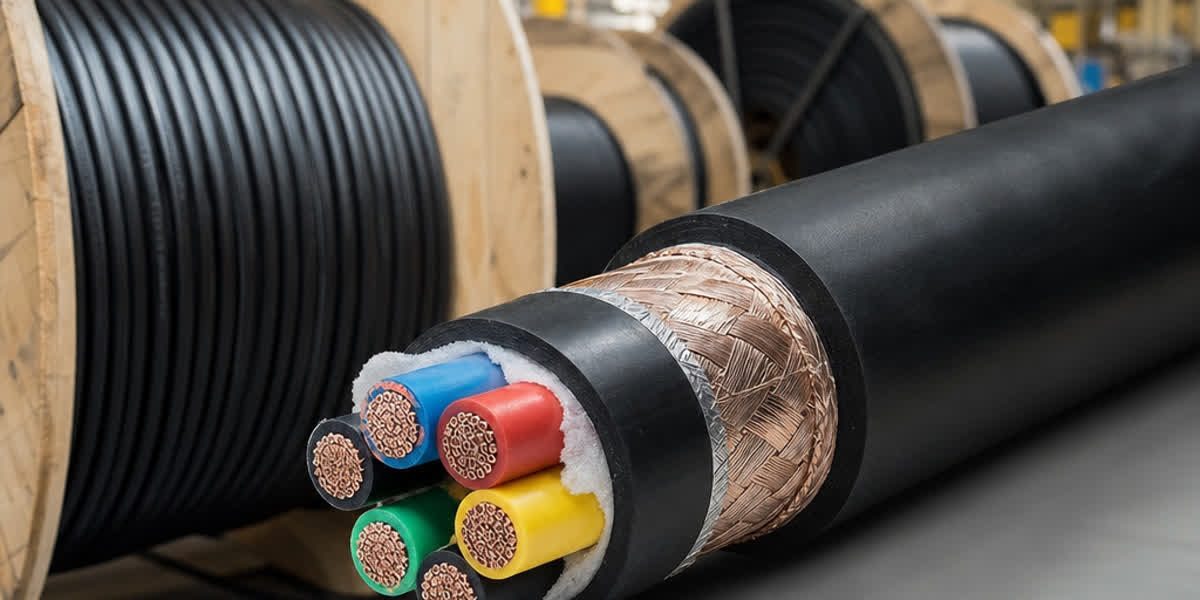
Underground cable installation is a critical infrastructure practice for power distribution, offering significant advantages over overhead lines in urban environments, environmentally sensitive areas, and locations where reliability is paramount. With global urbanization accelerating and grid reliability requirements increasing, underground cable systems are projected to grow at 7.5% CAGR through 2030, reaching a market value of over $45 billion according to MarketsandMarkets.
Unlike overhead lines, underground cables require careful route planning, specialized installation equipment, and strict adherence to international standards for trenching, backfilling, and cable laying. A poorly installed underground cable can fail prematurely, leading to costly excavation and repair work.
This guide provides project managers, utility engineers, and infrastructure contractors with a comprehensive reference for underground cable installation, covering trenching specifications, cable laying methods, jointing best practices, and global standards compliance.
International Standards for Underground Cable Installation
Underground cable installation must comply with the following key international standards:
| Standard | Scope | Key Requirements |
|---|---|---|
| IEC 60228 | Conductors of insulated cables | Conductor classes, stranding, resistance |
| IEC 60364-5-52 | Selection and erection of electrical wiring - Current-carrying capacities | Derating factors for burial depth, soil thermal resistivity |
| IEC 60502-1/2 | Power cables with extruded insulation (1kV–30kV) | Cable construction, test requirements |
| IEEE 400-2021 | Guide for Field Testing and Evaluation of Power Cable Systems | Test voltage levels, acceptance criteria |
| IEEE 575 | Guide for the Application of Sheath-Bonding Methods | Sheath bonding design for cable systems |
| CIGRE TB 732 | Recommendations for Cable Accessories Installation | Jointing, termination quality control |
| BS 7671 (IET Wiring Regulations) | UK requirements for electrical installations | Burial depth, warning tape, ducting |
| EN 50618 | Electric cables for photovoltaic systems | UV resistance, temperature rating |
| NF C 13-200 | French standard for HV installations | Specific trench and protection requirements |
Trench Excavation and Preparation
Trench Dimensions
Trench dimensions depend on cable type, voltage rating, number of cables, and soil conditions:
| Voltage Level | Recommended Depth (mm) | Minimum Trench Width (mm) | Sand Bed Thickness (mm) |
|---|---|---|---|
| LV (<1kV) | 600–750 | 300–450 | 75–100 |
| MV (1kV–33kV) | 750–900 | 400–600 | 100–150 |
| HV (33kV–150kV) | 1000–1300 | 600–900 | 150–200 |
| EHV (>150kV) | 1300–1800 | 800–1200 | 200–250 |
Note: Depths referenced from BS 7671 and IEC 60364-5-52. Local regulations may differ. Always verify with local utility standards.
Excavation Best Practices
-
Route Survey: Perform GPR (Ground Penetrating Radar) survey before excavation to identify existing utilities. Call "811" (US) or equivalent local utility location service.
-
Soil Assessment: Conduct soil thermal resistivity (Rho) testing per IEEE 442. Recommended values:
- Sandy soil: 0.7–1.0 K·m/W
- Clay soil: 0.8–1.5 K·m/W
-
Backfill sand: ≤1.2 K·m/W
-
Trench Water Management: For waterlogged areas, install a drainage system (perforated pipe + gravel sump) at the bottom of the trench base.
-
Spoil Management: Place excavated soil on the opposite side from the working area, minimum 0.5m from trench edge.
Cable Laying Methods
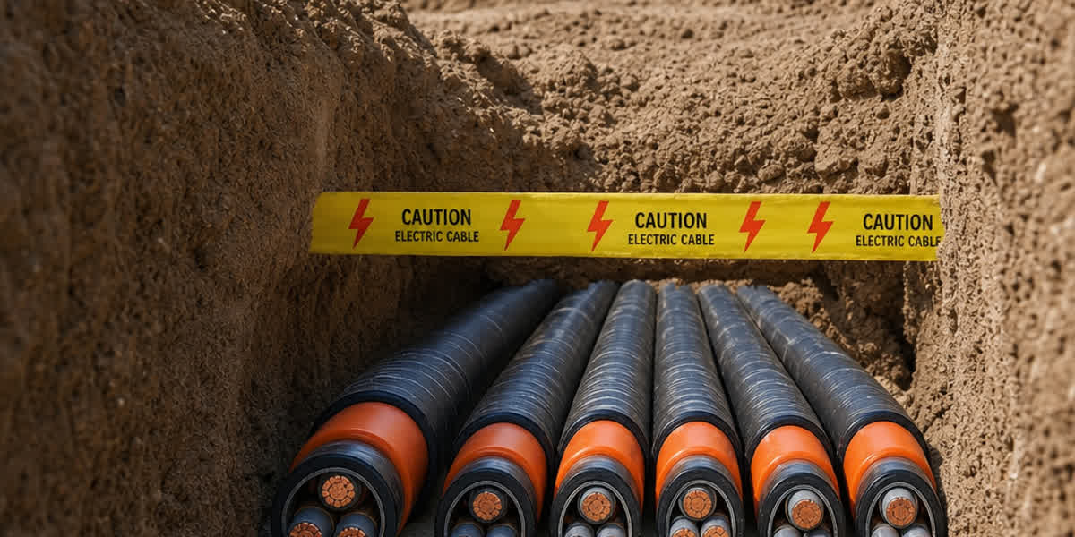
Method 1: Direct Burial
Direct burial is the most economical method, suitable for rural areas and low-traffic routes.
- Procedure:
- Excavate trench to required depth
- Lay 75–150mm sand bedding (compacted)
- Place cable(s) with appropriate spacing (≥7× cable diameter for single-core cables)
- Cover with 75–150mm sand
- Install mechanical protection (concrete tiles or protective slabs) 300mm above cable
- Install yellow warning tape 150–250mm below finished grade
- Backfill with selected soil, compacted in 150mm layers
| Cable Type | Minimum Spacing (center-to-center) | Bend Radius |
|---|---|---|
| LV Armored (single core) | 7× D | 12× D |
| LV Armored (multicore) | N/A | 12× D |
| MV Armored | 7× D | 15× D |
| HV XLPE (single core) | 200mm (triplex) or 7× D | 20× D |
D = cable outer diameter
Method 2: Duct/Conduit Installation
Preferred in urban areas where future cable replacement or addition is anticipated.
- Duct Materials:
- HDPE (High-Density Polyethylene) — most common, ±50mm–200mm diameter
- PVC — cost-effective for LV applications
- Steel — for road crossings and areas needing high mechanical protection
-
Pre-cast concrete troughs — for HV/EHV multiple cable circuits
-
Installation Requirements per IEC 61386:
- Minimum duct gradient: 1:200 for drainage
- Duct sealing at both ends with watertight seals
- Draw pit spacing: every 100–150m (or at every change of direction)
- Maximum pulling tension: 50N/mm² for copper, 40N/mm² for aluminum
- Pulling lubricant: water-based polymer (never petroleum-based)
Method 3: Cable Trench/Trough
Common in industrial plants, substations, and utility corridors.
- Pre-cast concrete troughs with removable covers
- Cable trays or ladder racks within the trough
- Adequate drainage at the bottom
- Fire-stopping barriers every 20m for HV installations
Cable Pulling Specifications
Maximum Pulling Tension
| Conductor Material | Single Cable | Multiple Cables (per cable) |
|---|---|---|
| Copper | 50 N/mm² | 35 N/mm² |
| Aluminum | 40 N/mm² | 28 N/mm² |
| ACSR (overhead) | 90 N/mm² (steel core) | — |
Side Wall Pressure
- Maximum side wall pressure: 300 kg/m (3 kN/m) for standard XLPE cables
- Reduced to 200 kg/m (2 kN/m) for EPR cables and self-supporting cables
- Measured at bends: SWP = T/R (Tension / Bend Radius)
Pulling Checklist
- ✅ Swivel-type pulling eye attached to conductor (not sheath)
- ✅ Cable lubricant compatible with jacket material
- ✅ Tension dynamometer in-line with pulling cable
- ✅ Pulling speed: 5–15 m/min for LV, 3–10 m/min for MV/HV
- ✅ Two-way communication maintained between puller and feed end
- ✅ Cable not dragged on ground during payout
Cable Jointing and Termination
Jointing Best Practices
Per CIGRE TB 732 and IEC 60502-4:
- Clean Room Conditions: Maintain humidity <60%, temperature 5–40°C
- Shelf Life Check: Verify accessory expiry dates before installation
- Semi-conductive Layer Removal: Use ceramic blade or specialized tool — never use abrasive wheels
- Insulation Cleanliness: Isopropyl alcohol wipe, no lint residue
- Timing: Complete the entire joint in one continuous operation — do not leave partial work overnight
- Test Before Energizing: DC hi-pot test per IEEE 400 or VLF (Very Low Frequency) test per IEEE 400.2
Common Joint Types
| Joint Type | Voltage Range | Application | Installation Time |
|---|---|---|---|
| Resin Cast | LV (<1kV) | Emergency repairs, temporary | 30–45 min |
| Heat Shrink | LV–MV (1kV–36kV) | General purpose indoor/outdoor | 45–90 min |
| Cold Shrink | LV–MV (1kV–36kV) | Confined spaces, where heat source unavailable | 20–60 min |
| Premolded Slip-on | HV (36kV–245kV) | Factory-tested quality, consistent | 60–120 min |
| Gas-filled | EHV (>245kV) | High-reliability transmission | 4–8 hours |
Backfilling and Restoration
- First Layer: Cable sand cover (75–150mm), hand-tamped, no sharp objects
- Protective Layer: Concrete slabs or bricks (ASTM C90 or equivalent)
- Warning Tape: Bright yellow "CAUTION — BURIED ELECTRIC CABLE" tape
- Main Backfill: Removed soil, free of rocks >50mm, compacted to 85–90% Proctor density
- Topsoil: Final 150–200mm, suitable for grass seeding or pavement restoration
- Restoration: Match original surface condition as closely as possible
Thermal Considerations and Ampacity Derating
Burial Depth Derating
| Burial Depth (mm) | Derating Factor (BS 7671) |
|---|---|
| 500 | 1.00 |
| 700 | 0.96 |
| 1000 | 0.89 |
| 1200 | 0.84 |
| 1500 | 0.78 |
Soil Thermal Resistivity Derating
| Soil Rho (K·m/W) | Derating Factor (IEC 60364-5-52) |
|---|---|
| 0.7 (moist sand) | 1.10 |
| 1.0 (standard sand) | 1.00 |
| 1.5 (clay/dry sand) | 0.85 |
| 2.0 (dry soil) | 0.73 |
| 2.5 (very dry / gravel) | 0.65 |
Key Insight: Many installation failures result from ignoring thermal derating. A cable rated for 300A in free air may only carry 210A when buried in dry soil at 1.2m depth. Always perform ampacity calculations based on actual site conditions using software like CYMCAP or ETAP.
Horizontal Directional Drilling (HDD) for Cable Installation
HDD is the preferred method for road crossings, river crossings, and environmentally sensitive areas.
| HDD Parameter | Recommendation |
|---|---|
| Minimum bend radius | 35× D (to allow for product pulling after pilot) |
| Entry angle | 8°–15° |
| Exit angle | 5°–12° |
| Mud pressure | <10 bar above overburden pressure |
| Pullback speed | 3–8 m/min |
| Swivel use | Double-swivel configuration mandatory |
Common Installation Defects and Prevention
| Defect | Cause | Prevention |
|---|---|---|
| Cable jacket abrasion | Dragging on rough ground during pull | Use cable rollers at entry/exit; protective socks |
| Sheath fold/kink | Bend radius exceeded | Calculate minimum radius before pulling |
| Water ingress at joint | Incomplete seal or inadequate moisture barrier | Use mastic strips + cold shrink transition |
| Insulation damage | Semi-con layer removed with abrasive tool | Use ceramic-blade stripper |
| Metallic sheath fracture | Excessive bending during cold weather | Minimum installation temp: -5°C for PVC, -15°C for XLPE |
| Conductor corrosion | Moisture in duct system | Seal ducts at both ends; pre-pull test mandrel |
FAQ
Q1: What is the minimum burial depth for LV power cables? For LV cables (<1kV), the standard minimum depth is 600mm (BS 7671). For agricultural land or areas subject to vehicular traffic, increase to 750mm. In rocky ground, use steel wire armored cable and install at 500mm minimum with concrete slab protection.
Q2: Can different voltage cables share the same trench? Yes, but separation requirements per IEC 60364 must be met: LV and MV cables require minimum 200mm clearance. Communications cables require ≥300mm separation from LV and ≥500mm from HV. Alternatively, use segregated troughs.
Q3: How do I detect existing underground cables before digging? Use a combination of Cable Avoidance Tool (CAT), GPR survey, and local utility locates. In the UK, contact "Dial Before You Dig" (LinesearchbeforeUdig). In the US, call 811. Internationally, many countries operate similar one-call centers.
Q4: What is VLF testing and why is it used? Very Low Frequency (VLF) testing (0.01–1.0 Hz) is the preferred field acceptance test for MV and HV cables per IEEE 400.2. Unlike DC hi-pot testing, VLF testing does not cause space charge accumulation in XLPE insulation, providing a more reliable assessment of insulation integrity.
Q5: How long does an underground cable installation last? Properly installed and maintained XLPE-insulated cables have a service life of 30–50 years. Key factors affecting longevity: installation quality, load cycling frequency, thermal environment, and moisture protection. Periodic partial discharge testing (per IEC 60270) can identify developing faults.
Q6: Do I need to use sand bedding for all underground cables? Sand bedding is recommended for all direct-buried cables to provide uniform thermal environment and mechanical protection. For duct installations, sand surround of ducts is used for thermal enhancement. In rocky soil, sand bedding is mandatory.
Q7: What is the recommended spacing between parallel underground cables? For single-core cables in parallel, maintain minimum 7× cable diameter spacing to allow mutual heating dissipation. For multicore cables, the spacing requirement is less critical but minimum 150mm is recommended for maintenance access.
Q8: Can underground cables be repaired if damaged? Yes. Repair methods include: pre-molded joint kits (factory-tested, highest reliability), cold shrink repair sleeves (good for low voltage emergency repairs), and resin injection kits (temporary repairs). All repairs should be VLF tested before re-energization.
Internal Links
For related products and guides, visit our product pages:
- LV Power Cable Selection Guide
- MV Power Cable Technical Specifications
- ACSR Conductor Specifications
- Concentric Cable Selection
- Guide to Purchasing Cables
- OPGW: Dual Power and Communication Functions
Contact Sitong Cable
Sitong Cable, founded in 2010, is an ISO 9001:2015 certified manufacturer with 200,000m² of production facilities. We supply underground cables in armored (SWA, AWA), unarmored, and duct-grade configurations to match your project specifications.
Contact us for a quote or technical consultation: - 📞 Phone: 0371-69176007 - 📧 Email: sales@sitongcable.com - 🌐 Website: www.sitongcable.com