ACSR Conductor Installation & Maintenance: Complete Technical Guide
ACSR Conductor Installation & Maintenance: Complete Technical Guide
ACSR (Aluminum Conductor Steel Reinforced) conductors are the backbone of modern overhead power transmission. Proper installation and maintenance are critical to ensuring long-term reliability, minimizing electrical losses, and preventing costly failures. This guide covers ACSR conductor installation best practices, sag-tension calculations, splicing techniques, routine maintenance schedules, and troubleshooting — aligned with international standards including IEEE 524, IEC 61089, ASTM B232, BS 215, and CIGRE Technical Brochures.
1. Introduction to ACSR Conductor Systems
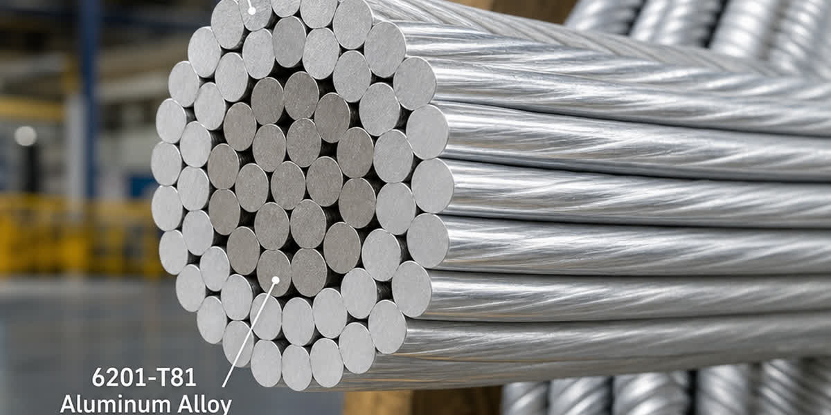
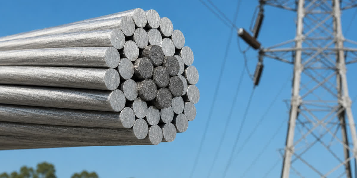
ACSR conductors consist of a galvanized steel core surrounded by one or more layers of stranded aluminum wires. The steel core provides mechanical strength, while the aluminum layers carry the electrical current. This composite design makes ACSR the most widely used overhead conductor for transmission and distribution lines from 11 kV up to 765 kV.
Key Characteristics: - Steel core (galvanized, Class A/B/C per ASTM B498): provides tensile strength and supports ice/wind loading - Aluminum strands (1350-H19, per ASTM B230): conduct current with excellent corrosion resistance - Layered stranding: concentric lay, alternating direction for balance and mechanical stability - Weight-to-strength ratio: superior to solid conductors, enabling longer spans
🔗 Explore our ACSR product range: ACSR Conductors Page
2. Pre-Installation Preparation
2.1 Receiving and Storage
| Activity | Standard/Best Practice |
|---|---|
| Inspection on receipt | Check drum condition, shipping damage per ASTM B232 Section 12 |
| Storage | Keep on hard, level surface; drums on chocks to prevent rolling |
| Coverage | Protect with waterproof tarp; allow airflow to prevent condensation |
| Shelf life | Indefinite if stored properly; inspect galvanized core annually |
| Handling | Use spreader bars and nylon slings to avoid crushing aluminum strands |
2.2 Tool and Equipment Checklist
- Conductor pulling equipment: bullwheel tensioner (≤ 20% rated breaking strength tension), puller with swivel
- Running boards and rollers: non-metallic or neoprene-lined to protect aluminum
- Splicing tools: hydraulic compression tool with dies, shear-head or hex crimp
- Hot-line tools: shotgun sticks, clamp sticks, tension tools (for live-line work)
- Dynamometer: calibrated load cell for tension measurement
- Sag measurement tools: transit/theodolite, dynamic sag meter, or GPS-based systems
- Grounding equipment: per IEEE 524 and OSHA / local safety codes
2.3 Conductor Stringing Plan
A pre-construction stringing plan must include: 1. Pulling section lengths (typically 2–5 km) 2. Setup and tail locations 3. Crossing protection (roads, railways, other power lines) 4. Sag-tension calculations for the specific span profile and temperature range 5. Sequence of stringing (tensioner → traveler → puller)
🔗 Related reading: ACSR Conductor Selection Guide for 11kV–33kV
3. Sag-Tension Calculations
Sag-tension is the most critical engineering parameter for ACSR installations. Incorrect sag leads to clearance violations, galloping, or excessive tension.
3.1 Design Parameters
| Parameter | Typical Value / Source |
|---|---|
| Initial unloaded tension | 15–20% of RBS (Rated Breaking Strength) |
| Final tension (after creep) | 20–25% of RBS |
| Maximum design tension | 60% of RBS (under extreme ice/wind) |
| Everyday stress | ≤ 18% of RBS for ACSR to avoid vibration damage |
| Ambient temperature range | -40°C to +50°C (project-specific) |
| Ice loading | Per IEC 60826 or local code (e.g., 12.5 mm radial ice) |
| Wind loading | Per IEC 60826 (e.g., 140–900 Pa) |
3.2 Sag Computation Methods
- Catenary equations (exact): for long spans where the conductor's self-weight is the dominant load
- Parabolic approximation: sufficient for level spans under 500 m
- Ruling span method: simplifies multi-span sections to a single equivalent span
Key Formula (Parabolic Sag):
sag = (w × S²) / (8 × T)
Where: w = conductor weight per unit length, S = span length, T = horizontal tension
3.3 Creep and Thermal Sag
ACSR exhibits two types of sag increase over time: | Type | Cause | Magnitude | |------|-------|-----------| | Initial creep | Strand settlement (first few weeks) | 0.05–0.15% of span length | | Thermal sag | Conductor heating due to load current | Up to 3–5× cold sag at rated temperature | | Long-term creep | Aluminum and steel permanent elongation | 0.02–0.04% per year (decreases over time) |
💡 ACSR's steel core limits long-term creep significantly compared to all-aluminum conductors (AAC).
4. Conductor Stringing Procedure
4.1 Tension Stringing
Modern installations use tension stringing (also called controlled-tension stringing) to prevent conductor damage.
| Step | Action | Key Requirement |
|---|---|---|
| 1 | Set up tensioner and puller | Tensioner brakes calibrated to ≤20% RBS |
| 2 | Install travelers (stringing sheaves) | Sheave diameter ≥ 20× conductor diameter; neoprene-lined |
| 3 | Thread pilot line | Use swivels to prevent twist |
| 4 | Pull conductor through travelers | Maintain 10–15% RBS tension; avoid dragging on ground |
| 5 | Clipping-in (transfer to suspension clamps) | Use armor rods at suspension points |
| 6 | Dead-end terminations | Compression dead-ends per manufacturer spec |
4.2 Splicing
Compression splices are the industry standard for ACSR:
| Splice Type | Application | Tooling |
|---|---|---|
| Full-tension splice | Mid-span joints, must carry 100% RBS | Hydraulic press, two-steel-die sequence |
| Repair sleeve | Damaged strand repair (up to 2 damaged strands) | Hydraulic or hand crimp |
| Live-line splice | Emergency repair under energized conditions | Hot-line tools + jumper bypass |
Critical rules for splicing: - Never splice within 15 m of a suspension or dead-end clamp - Stagger splices in adjacent spans per IEEE 524 - Full-tension splices must be tested to ≥95% RBS for acceptance - Remove all aluminum oxide with a wire brush before inserting into the splice
4.3 Vibration Mitigation
ACSR in long spans and high-tension applications is prone to aeolian vibration:
| Countermeasure | Application | Standard |
|---|---|---|
| Stockbridge dampers | Typical spans > 200 m; moderate vibration | IEEE 664 |
| Spacer dampers | Bundle conductors (2+ subconductors) | IEEE 524 |
| Armor rods | Stress distribution at suspension clamps | ASTM B725 |
| Vibration recorders | Monitor vibration levels; deploy for first 6–12 months | CIGRE TB 951 |
🔗 View our overhead line accessories: Transmission Line Hardware
5. Inspection and Testing After Installation
5.1 Post-Stringing Inspection Checklist
| Item | Criteria |
|---|---|
| Conductor sag | Within ±2% of design value at reference temperature |
| Clearances | ≥ minimum per IEC 61936-1 or local regulation |
| Splice pull-through | All splices verified visually and by X-ray (if specified) |
| Damper installation | Correct number, position per vibration study |
| Structure attachments | No sharp edges, no abrasion points |
| Grounding continuity | Verified across all structures |
5.2 Corona and Radio Interference
- Conduct visual corona inspection at night or with UV (daytime corona camera)
- Check for damaged strands, sharp objects, and contaminated insulators
- RI levels per CISPR 18-2 should not exceed 50 dB above 1 µV at 1 km from line
6. Routine Maintenance Schedule
| Frequency | Maintenance Activity |
|---|---|
| Monthly | Visual patrol (roads, crossings, vegetation) |
| Quarterly | Inspect dampers, spacers, and armor rods |
| Semi-annual | Thermal imaging of splices and dead-ends |
| Annual | Sag measurement; compare to design values |
| Every 3 years | Full ground inspection with binoculars; check for corrosion |
| Every 5 years | Climb-and-inspect selected structures; sample splice resistance |
| Every 10 years | Detailed mechanical audit; replace dampers |
7. Troubleshooting Common Issues
| Problem | Likely Cause | Solution |
|---|---|---|
| Excessive sag | Overload, high ambient temp, or creep beyond design | Re-tension; verify load profile; consider reconductoring |
| Corrosion (white rust) | Coastal/industrial exposure on aluminum | Clean with non-metallic brush; apply inhibitor |
| Corrosion (red rust) | Galvanized core exposed; moisture ingress | Replace span; check splice seals |
| Broken strands | Vibration fatigue or galloping | Install dampers; repair sleeve |
| High splice temperature | Poor compression or oxidation | Re-crimp or replace splice |
| Galloping | Ice accretion + wind, moderate tension | Install interphase spacers or aerodynamic dampers |
| Bird-streamer flashovers | Pollution on insulators | Increase creepage distance; install bird guards |
8. Safety Considerations
| Hazard | Precaution |
|---|---|
| Induced voltage | Ground all conductors during stringing; use personal grounding |
| Pulling tension | Stay clear of tensioner/puller zones; use remote controls |
| Falling objects | Hard hats, safety zones beneath towers |
| Live-line work | Minimum approach distances per OSHA 1910.269 or IEC 61936-1 |
| Corona discharge | Personal protective equipment (PPE) with conductive suit for EHV |
9. Frequently Asked Questions
Q1: What is the maximum span length for ACSR? Typical spans range from 100 m (distribution) to 1,200 m (transmission). Longer spans are possible with larger sections and special vibration mitigation.
Q2: How often should ACSR conductors be inspected? Visual monthly patrols, annual sag measurement, and detailed inspection every 3–5 years. Thermal imaging of splices every 6 months is recommended.
Q3: Can ACSR be used in coastal environments? Yes, with proper corrosion protection. Specify heavier galvanizing (Class B or C) on the steel core, and consider AAC (all-aluminum) for extreme marine exposure.
Q4: What is the recommended compression pressure for ACSR splices? Follow manufacturer specifications. Typical hydraulic pressure ranges from 70–120 MPa depending on the splice design and die type.
Q5: How do you detect hidden corrosion in ACSR? Use resistance measurement (micro-ohmmeter), X-ray inspection, or thermal imaging under load. A 20% increase in splice resistance indicates developing corrosion.
Q6: What tools are needed for tension stringing? Bullwheel tensioner, puller (winch), stringing sheaves (travelers), swivels, dynamometer, running boards, and grounding equipment.
Q7: What standards govern ACSR installation? IEEE 524 (Guide for Installation of Overhead Transmission Line Conductors), IEC 61089 (Round wire concentric lay overhead electrical stranded conductors), ASTM B232 (Concentric-Lay-Stranded Aluminum Conductors, Steel-Reinforced), BS 215, and local utility standards.
10. References and Standards
| Standard | Description |
|---|---|
| IEEE 524-2016 | Guide for the Installation of Overhead Transmission Line Conductors |
| IEC 61089 | Round wire concentric lay overhead electrical stranded conductors |
| ASTM B232 | Standard Specification for ACSR |
| ASTM B498 | Standard Specification for Zinc-Coated Steel Core Wire for ACSR |
| ASTM B230 | Standard Specification for Aluminum 1350-H19 Wire |
| BS 215 | Specification for Aluminum Conductors and Aluminum Conductors Steel Reinforced |
| IEC 60826 | Design Criteria of Overhead Transmission Lines |
| CIGRE TB 951 | Guide on Conductor Vibration and Mitigation |
| CISPR 18-2 | Radio Interference Characteristics of Overhead Power Lines |
| IEC 61936-1 | Power Installations Exceeding 1 kV |
About Sitong Cable
With over 20 years of manufacturing experience, Sitong Cable is a trusted supplier of ACSR conductors, AAC/AAAC cables, ABC cables, and power cables to global markets. Our ACSR product line complies with ASTM, IEC, BS, and DIN standards, and we serve customers in transmission and distribution projects across Asia, Africa, the Middle East, and South America.
🌐 Get a quote for ACSR conductors: Contact Us or email sales@sitongcable.com 📖 More technical guides: Sitong Blog