Concentric Cable Complete Technical Guide: Standards, Selection & Installation (IEC 60502, BS 7870)
Concentric Cable Complete Technical Guide: Standards, Selection & Installation (IEC 60502, BS 7870)
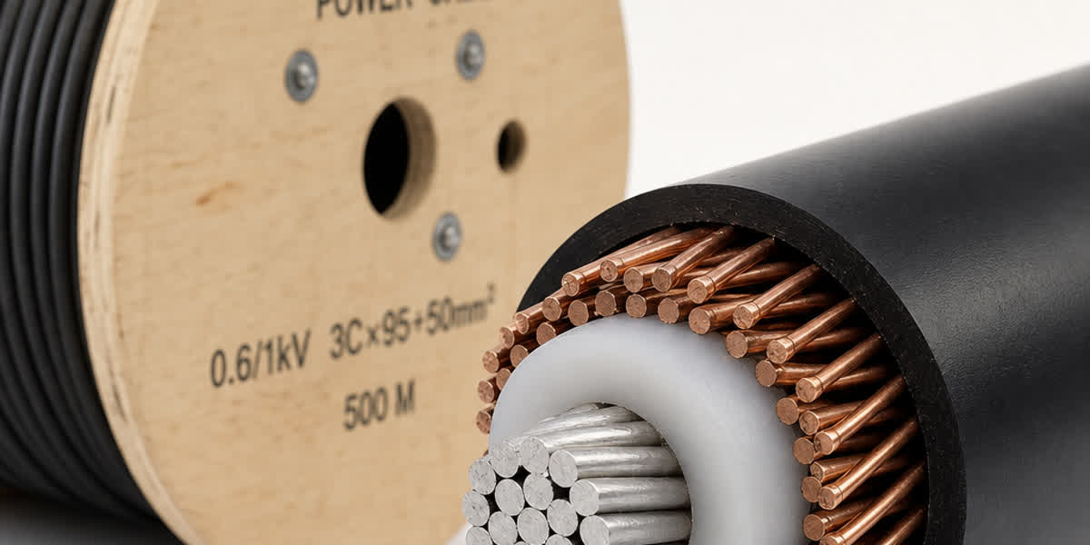
Concentric cables are a specialized type of power cable where the neutral conductor is arranged as a concentric layer of wires around the insulated phase conductor(s), rather than as a separate parallel core. This design delivers a unique combination of electrical performance, mechanical robustness, and installation efficiency that makes it the preferred choice for service entrance, street lighting, and LV distribution networks across the globe.
This comprehensive technical guide is designed for electrical engineers, utility specifiers, and procurement professionals who need authoritative reference data — from international standards and conductor configurations to selection methodology, installation practices, and application-specific case studies.
1. Concentric Cable Overview & Applications
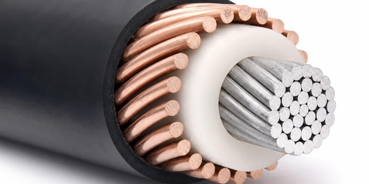
A concentric cable typically consists of a stranded copper or aluminum phase conductor, extruded XLPE or PVC insulation, and one or more concentric layers of neutral wires (generally bare copper or aluminum) applied helically over the insulation. An outer PVC or PE jacket provides mechanical and environmental protection.
The defining characteristic is the concentric neutral: helically applied wires that serve as both the neutral/grounding conductor and a protective armor. This dual function eliminates the need for a separate neutral core, reducing cable diameter, weight, and installation cost.
Standard Voltage Classes
| Voltage Class | Typical Rating | Primary Applications |
|---|---|---|
| Low Voltage (LV) | 0.6/1 kV | Service entrance, street lighting, LV distribution |
| Medium Voltage (MV) | 3.6/6 kV – 19/33 kV | Underground distribution, industrial feeders |
Applications Table
| Application | Description | Recommended Variant |
|---|---|---|
| Service Entrance (USA/Canada) | Underground supply from utility transformer to building meter | 600 V concentric neutral cable per ICEA S-76-474 / UL 1277 |
| Street & Area Lighting | Feeder and branch circuits for pole-mounted luminaires | 0.6/1 kV single-core concentric, PVC sheathed |
| LV Underground Distribution | Last-mile residential/commercial underground networks | IEC 60502-1 0.6/1 kV, aluminium conductor, XLPE insulated |
| MV Utility Distribution | 11 kV to 33 kV primary distribution circuits | IEC 60502-2 / BS 7870-4, copper or aluminium conductor, XLPE insulated |
| Industrial Feeder Circuits | In-plant power distribution where mechanical protection is needed | Concentric neutral or wire-armored per IEC 60502 |
| Renewable Energy — Solar Farms | Array-to-inverter underground runs with combined neutral/ground | 0.6/1 kV single-core or 3-core concentric, UV-rated jacket |
| Temporary Construction Power | Rugged, single-cable runs reduced installation time | 0.6/1 kV concentric with heavy-duty PE sheath |
💡 Key Advantage: A single concentric cable replaces the multi-cable bundle required by conventional designs — reducing trench width by 30–50% and cutting installation labor by up to 40% in LV distribution applications.
2. International Standards Reference
Concentric cables are governed by an extensive framework of international standards. Specifiers must match the standard to the project jurisdiction.
| Standard | Title | Scope / Region | Key Requirements |
|---|---|---|---|
| IEC 60502-1 | Power cables with extruded insulation — Part 1: Cables for rated voltages 1 kV (Um=1.2 kV) and 3 kV (Um=3.6 kV) | International | Construction, test methods, concentric conductor design |
| IEC 60502-2 | Power cables with extruded insulation — Part 2: Cables for rated voltages 6 kV (Um=7.2 kV) to 30 kV (Um=36 kV) | International | MV cable construction, partial discharge tests, semi-conductive layers |
| BS 7870 | LV and MV polymeric insulated cables for use by distribution and generation utilities | UK (LV + MV) | Full construction + performance specification for concentric cables |
| BS 7870-1 | LV cables with concentric neutral — general requirements | UK | 0.6/1 kV concentric neutral cables, conductor sizes 16–300 mm² |
| BS 7870-2 | MV cables with concentric neutral for 11 kV to 33 kV | UK | MV concentric neutral cable for UK DNO networks |
| ICEA S-76-474 | Neutral-Spaced Power Cables (NS) | USA | 600 V concentric neutral cable construction |
| UL 1277 | Electrical Power and Control Tray Cables with Optional Optical Fiber | USA | Safety standard for concentric neutral power cables |
| AEIC CS8 | Specification for Extruded Dielectric Shielded Power Cables | USA | MV cable specification referenced by ICEA |
| AS/NZS 1429 | Electric cables — Polymeric insulated — For working voltages up to and including 0.6/1 kV | Australia / New Zealand | Includes concentric cable construction for LV distribution |
| GOST 31947 | Power cables with plastic insulation for rated voltages 0.66; 1 and 3 kV | Russia / CIS | LV concentric cable construction and test requirements |
| NBR 7286 | Power cables with XLPE insulation for rated voltages up to 1 kV | Brazil | Concentric cable construction for LV networks |
| UNE 21123 | Power cables with rated voltage 0.6/1 kV | Spain | LV concentric cable types |
🏗️ Project Tip: For UK DNO (Distribution Network Operator) projects, BS 7870 is mandatory. For international tenders, IEC 60502 is almost universally accepted. For North American utility work, reference ICEA S-76-474 and UL 1277.
3. Concentric Cable Types & Specifications
3.1 Low Voltage (0.6/1 kV) Concentric Cables — IEC 60502-1 / BS 7870-1
| Designation | Conductor Material | Conductor Cross-Section (mm²) | Insulation | Concentric Neutral | Outer Sheath | Application |
|---|---|---|---|---|---|---|
| CN-1L-A | Aluminium, stranded | 16–300 | XLPE | Copper wires, helical lay | PVC (ST2) | LV distribution, service |
| CN-1C-A | Aluminium, stranded | 16–300 | XLPE | Copper wires, helical lay | PE (ST7) | LV distribution, direct burial |
| CN-1L-C | Copper, stranded | 10–240 | XLPE | Copper wires, helical lay | PVC (ST2) | LV distribution, industrial |
| CN-1C-C | Copper, stranded | 10–240 | XLPE | Copper wires, helical lay | PE (ST7) | LV distribution, direct burial |
| CN-1P-A | Aluminium, solid | 16–120 | PVC (70°C) | Copper wires, helical lay | PVC | Street lighting, temporary |
| CN-1P-C | Copper, solid | 6–95 | PVC (70°C) | Copper wires, helical lay | PVC | Internal / conduit runs |
Selection Note: Aluminium conductors reduce cost by approximately 30% compared with copper at equivalent ampacity. PE sheath provides superior moisture resistance for direct burial — always spec PE (ST7) for underground trench installations.
3.2 Medium Voltage (11 kV – 33 kV) Concentric Cables — IEC 60502-2 / BS 7870-2
| Type | Voltage Class (kV) | Conductor Size (mm²) | Insulation Thickness (mm) | Concentric Neutral | Application |
|---|---|---|---|---|---|
| CN-MV-11 | 6.35/11 (12.7/22) | 16–630 | 3.4 (XLPE) | Copper wires, 1.0–2.5 mm Ø | Primary distribution, 11 kV |
| CN-MV-33 | 19/33 (36 kV) | 25–630 | 5.5 (XLPE) | Copper wires, 1.0–2.5 mm Ø | Primary distribution, 33 kV |
| CN-MV-15 | 8.7/15 (17.5 kV) | 16–630 | 4.5 (XLPE) | Copper wires, 1.0–2.5 mm Ø | 15 kV class distribution (US/Asia) |
All MV concentric cables include: - Conductor: stranded circular or compacted copper/aluminium - Inner semi-conductive layer (conductor screen) - XLPE insulation - Outer semi-conductive layer (insulation screen) - Copper tape or wire concentric neutral - Optional: PVC or PE outer sheath
Selection Note: For 11 kV networks, CN-MV-11 with 3.4 mm XLPE insulation is the standard choice. Where soil conditions are corrosive, upgrade from bare copper neutral wires to a tinned copper or lead-alloy wrapped design.
3.3 Concentric Neutral Wire Configurations
| Neutral Type | Wire Diameter (mm) | Number of Wires | Coverage (% of circumference) | Application |
|---|---|---|---|---|
| Standard helical | 1.0–2.5 | 6–36 | 40–60% | General LV/MV distribution |
| Tight-pitch helical | 1.0–2.5 | 12–48 | 60–80% | Higher fault-current capacity |
| Open helical | 1.0–2.5 | 4–8 | 25–40% | Street lighting, low fault current |
| Copper tape | 0.1–0.3 (thick) | 1 (wrap) | 100% | MV cables, full neutral screening |
4. Selection Methodology
Follow this 5-step process to select the optimal concentric cable for your project.
Step 1: Define Electrical Requirements
| Parameter | Example Value | Notes |
|---|---|---|
| Nominal voltage (U₀/U) | 0.6/1 kV | System voltage |
| Maximum system voltage (Um) | 1.2 kV | IEC class |
| Rated current (load) | 200 A per phase | Base load |
| Fault current rating | 12 kA for 1 s | Neutral must withstand |
| Voltage drop limit | 4% (LV) / 5% (MV) | At farthest point |
| Ambient temperature | 25 °C (ground) / 40 °C (air) | Derating factor applied |
Step 2: Select Conductor Size from Ampacity Tables
Apply derating factors:
I_adjusted = I_base × K_temp × K_depth × K_group × K_soil
| Conductor Size (mm²) | Aluminium (A) | Copper (A) | Notes |
|---|---|---|---|
| 16 | 75 | 100 | Direct buried, 25°C |
| 25 | 95 | 130 | |
| 35 | 115 | 160 | |
| 50 | 140 | 195 | |
| 70 | 175 | 245 | |
| 95 | 210 | 295 | |
| 120 | 240 | 335 | |
| 150 | 275 | 380 | |
| 185 | 310 | 430 | |
| 240 | 365 | 510 | |
| 300 | 415 | 580 |
💡 Quick Rule: For LV aluminium concentric cables at 0.6/1 kV, a 95 mm² conductor typically serves 200 A residential feeders. Derate by 0.85 for grouped cables or high-ambient conditions.
Step 3: Check Voltage Drop
For 3-phase circuits:
ΔV = √3 × I × L × (R cos φ + X sin φ) / 1000
Where: - I = load current (A) - L = cable length (m) - R = AC resistance at operating temperature (Ω/km) - X = reactance (Ω/km) — for concentric cables, X is typically 0.08–0.12 Ω/km - cos φ = power factor
Simplify for LV aluminium (cos φ ≈ 0.95): - Typical voltage drop at 200 A, 300 m, 95 mm² Al: ≈ 4.2 V per phase (1.8% of 230 V) ✅
Step 4: Verify Neutral Fault Capacity
The concentric neutral must carry the full earth fault current without damage:
I_fault² × t ≤ K² × S²
Where: - K = constant for copper (143 for PVC, 176 for XLPE) - S = total neutral conductor cross-section (mm²)
Example: 95 mm² aluminium conductor with 6 × 2.0 mm copper neutral wires → S_neutral = 18.85 mm². For a 12 kA, 1 s fault: (12,000² × 1) = 144 × 10⁶ ≤ (176² × 18.85²) = 11 × 10⁶ ❌ — neutral is undersized. Upgrade to 12 × 2.0 mm wires (37.7 mm²).
Step 5: Evaluate Economic Options
| Option | Cable Type | Material Cost | Installation | Lifecycle | Best For |
|---|---|---|---|---|---|
| A — Standard | Aluminium conductor, XLPE insulated, PVC sheathed | Low | Standard | 30 years | Budget-conscious LV projects |
| B — Premium | Copper conductor, XLPE insulated, PE sheathed | Medium | Standard | 40+ years | Coastal, high-reliability |
| C — Heavy Duty | Aluminium, XLPE, PE sheath, enhanced neutral (12+ wires) | Medium | Standard | 40+ years | High fault-current locations |
5. Installation Practices
Pre-Installation Checklist
| Item | Requirement |
|---|---|
| Minimum bending radius | 12× overall cable diameter (15× for armoured) |
| Maximum pulling tension | 50 N/mm² per conductor (copper) / 30 N/mm² (aluminium) |
| Side-wall pressure limit | 500 N/m (LV) / 750 N/m (MV) |
| Ambient temperature range (installation) | −5 °C to +50 °C |
| Cable end sealing | Moisture-proof cap immediately after cutting |
Trench Installation (Direct Burial)
- Trench dimensions: minimum 600 mm width, 750 mm depth (LV) / 1,000 mm (MV below roads)
- Bedding: 100 mm sand layer below and 100 mm above cable
- Cable spacing: 150–200 mm between parallel concentric cables to maintain ampacity
- Warning tape: 200 mm above cable
- Backfill: fine soil free of sharp stones, compacted in 200 mm layers
Key Safety Rules
- ⚠️ Concentric neutral carries fault current — always ground both ends of the neutral wire bundle per local code
- ⚠️ Never bend to less than 12× OD — sharp bends damage the concentric wire helix
- ⚠️ Use pulling grips on the concentric wires — never pull on the conductor alone
- ⚠️ Verify neutral continuity after jointing with a low-resistance ohmmeter (< 0.1 Ω)
6. Case Study: Residential Subdivision LV Underground Network
Based on a typical UK residential development project profile
Project Parameters
| Parameter | Value |
|---|---|
| Application | 150-home residential estate underground LV network |
| Cable type | 0.6/1 kV concentric neutral, XLPE insulated, PE sheathed |
| Conductor | Aluminium, 95 mm² |
| Neutral | Copper wires, 12 × 2.0 mm (37.7 mm² total) |
| Route length | 1,200 m (main feeder) |
| Connected load | 400 kVA (200 A per phase estimated) |
| Standard | BS 7870-1 |
Option Comparison
| Parameter | Option A: Aluminium 95 mm² | Option B: Copper 70 mm² |
|---|---|---|
| Conductor cost | Reference (−35%) | +35% vs aluminium |
| Ampacity at 25°C | 210 A | 245 A |
| Voltage drop at 200 A, 1.2 km | 4.1% (within 4% limit) | 3.2% |
| Total material cost per metre | Reference | +45% |
| Neutral fault capacity | 12 kA × 1 s ✅ | 12 kA × 1 s ✅ |
| Recommendation | ✅ Selected (meets all requirements) | Over-specified |
✅ Result: Option A (Aluminium 95 mm² per BS 7870-1) was selected — meeting all electrical, mechanical, and fault-level requirements at the lowest installed cost.
7. Environmental & Durability Considerations
| Factor | Recommendation | Rationale |
|---|---|---|
| Direct burial in wet soil | PE (ST7) outer sheath | PE absorbs < 0.1% moisture vs PVC at 0.5% |
| Coastal / saline environment | PE sheath + tinned copper neutral | Salt corrosion accelerates bare copper degradation |
| Industrial zones (chemicals) | PE or LSZH (Low Smoke Zero Halogen) sheath | Chemical resistance, reduced toxic emissions in fire |
| High ambient temperature (>40°C) | XLPE insulation (90°C rated) | PVC rated 70°C only — XLPE required for uprating |
| High fault-current locations | Enhanced neutral (12+ copper wires) | Ensures adiabatic fault capacity is met |
| UV exposure (above-ground termination) | Black PE sheath for UV resistance | Standard PVC degrades in direct sunlight |
| Rocky terrain / abrasive backfill | Steel wire armour (SWA) over concentric neutral | Added mechanical protection |
8. FAQ
Q1: What is the difference between a concentric cable and a conventional armoured cable (SWA)?
Concentric cables use helically applied neutral wires as both the neutral conductor and mechanical protection. SWA cables have a separate steel wire armour layer. Concentric cables are generally lighter, more flexible, and lower cost for LV distribution where the neutral function is needed.
Q2: Can concentric cables be used for three-phase circuits?
Yes. 3-core concentric cables are available where three insulated phase conductors share a common concentric neutral. Single-core concentric cables can also be installed in triplex configurations for three-phase service.
Q3: What is the maximum continuous operating temperature for XLPE-insulated concentric cables?
XLPE insulation is rated for 90 °C continuous, 130 °C under overload, and 250 °C under short-circuit conditions (IEC 60502). PVC insulation is limited to 70 °C continuous.
Q4: How should concentric cable ends be terminated?
Strip the outer sheath carefully to avoid nicking the neutral wires. Terminate the concentric neutral wires with a ring-terminal or compression lug at both ends — do not leave unterminated. Apply anti-corrosion compound on copper terminations in coastal environments.
Q5: What bending radius is required for concentric cables?
The minimum recommended bending radius is 12× the overall cable diameter for unarmoured concentric cables, and 15× for armoured variants. For MV cables (11 kV+), refer to IEC 60502-2 which specifies 15× OD.
Q6: How do I calculate the neutral cross-section for fault current rating?
The total neutral cross-section = number of wires × π × (wire diameter/2)². For an adiabatic fault: S_neutral ≥ √(I²t) / K. Use K = 143 for PVC cables and K = 176 for XLPE cables (IEC 60364-5-54).
Q7: What is the typical lead time for custom concentric cable orders?
Standard LV concentric cables (0.6/1 kV) are typically available in 2–3 weeks for common sizes (16–300 mm², aluminium or copper). MV concentric cables (11–33 kV) require 4–6 weeks. For large orders (>10 km), consult the factory for specific lead times.
Q8: Can concentric neutral cables be used for both neutral and earth (PEN) functions?
Yes, in TN-C and TN-C-S earthing systems, the concentric neutral can serve as a combined PEN conductor provided the cross-section meets the minimum requirements of IEC 60364 — typically ≥ 10 mm² copper or ≥ 16 mm² aluminium. Verify with local electrical codes before installation.
9. Conclusion
Concentric cables offer a proven, cost-effective solution for LV and MV underground distribution worldwide. By integrating the neutral conductor into the cable construction as a concentric wire layer, they reduce material usage, simplify installation, and deliver reliable service over 30+ year lifetimes.
Key takeaways for specifiers: - Match the standard to your jurisdiction — IEC 60502 for international projects, BS 7870 for UK DNO networks, ICEA/UL for North America - Verify neutral fault capacity — the concentric neutral must be sized for the maximum prospective fault current - Select PE sheath for direct burial applications — its moisture resistance outperforms PVC in wet soil - For aluminium conductors, always compare total installed cost (material + installation + trenching) against copper options
👉 Browse our Concentric Cable range
👉 Contact our engineering team for project-specific selection assistance
This guide was prepared by the SiTong Cable engineering team. All technical data references IEC 60502, BS 7870, ICEA S-76-474, and UL 1277 standards. SiTong Cable has been manufacturing concentric cables to international standards since 2010.