HTLS Conductor (STACIR/AW): Complete Technical Guide — Standards, Specifications & Selection for High-Temperature Low-Sag Overhead Lines
Complete guide to HTLS STACIR/AW conductors — standards, specs, selection, and capacity upgrade without tower replacement.
1. Introduction
High-Temperature Low-Sag (HTLS) conductors represent a class of overhead transmission conductors engineered to operate continuously at elevated temperatures (150°C–210°C) while exhibiting significantly reduced thermal sag compared to conventional ACSR conductors. The defining advantage of HTLS technology is its ability to increase the ampacity of existing transmission corridors without modifying tower structures — a process known as reconductoring. By replacing aged or capacity-limited ACSR conductors with HTLS conductors on the same tower geometry, utilities can achieve 50–100% capacity gains while maintaining regulatory clearance requirements.
This guide is written for transmission line engineers, utility planning professionals, procurement specialists, and project managers evaluating HTLS solutions for line uprating, congestion relief, or new greenfield transmission projects. We focus specifically on STACIR/AW (Super Thermal-resistant Aluminum Conductor Invar Reinforced), also known as ZTACIR in some markets — an HTLS variant that combines a low-thermal-expansion invar (iron-nickel alloy) core with super thermal-resistant aluminum (ZTAL) strands for exceptional sag performance at high operating temperatures.
2. HTLS Conductor Types & Overview
Several HTLS conductor technologies have been commercialized, each using a different core material to reduce thermal sag. The table below summarizes the principal types.
| Type | Core Material | Max Continuous Operating Temp | Key Advantage |
|---|---|---|---|
| ACSS (Annealed Aluminum Conductor Steel Supported) | Galvanized steel (Class A, B, or C coating) | 250°C | Lowest cost; fully annealed Al strands carry no tension |
| STACIR/AW (Super Thermal-resistant Aluminum Conductor Invar Reinforced) | Invar (Fe-Ni alloy, 36% Ni) | 210°C | Lowest thermal expansion (~3 × 10⁻⁶/°C); excellent sag control |
| GTACSR (Gap-Type Thermal-resistant Aluminum Conductor Steel Reinforced) | Galvanized steel with grease-filled gap | 150°C | Self-damping; lower sag than conventional ACSR |
| ZTACIR (Zirconium Thermal-resistant Aluminum Conductor Invar Reinforced) | Invar (Fe-Ni alloy) | 210°C | Zirconium-doped Al for higher strength retention at temp |
| ACCR (Aluminum Conductor Composite Reinforced) | Aluminum oxide (Al₂O₃) fiber composite | 210°C | Lightweight; non-corrosive; highest strength-to-weight ratio |
Among these, STACIR/AW (also referred to simply as TACIR/AW in some regions) offers the best balance of thermal sag performance, cost, and field-proven reliability. The invar core — an iron-nickel alloy with approximately 36% nickel content — has a coefficient of thermal expansion (CTE) of roughly 3 × 10⁻⁶/°C, compared to 11.5 × 10⁻⁶/°C for galvanized steel. This dramatically reduces sag growth at high temperatures.
3. International Standards
HTLS conductors, including STACIR/AW, are governed by a framework of international standards covering thermal rating calculation, construction requirements, and sag-tension analysis.
| Standard | Title | Scope / Region |
|---|---|---|
| IEEE 738 | Standard for Calculating the Current-Temperature Relationship of Bare Overhead Conductors | Thermal rating and ampacity calculations (North America and global) |
| IEC 61089 | Round Wire Concentric Lay Overhead Electrical Stranded Conductors | General construction and test requirements (global/IEC) |
| ASTM B941 | Standard Specification for Concentric-Lay-Stranded Aluminum Conductors, Aluminum-Clad Invar (STACIR/AW) | Primary construction standard for STACIR/AW (North America) |
| ASTM B856 | Concentric-Lay-Stranded Aluminum Conductors Coated Steel Supported (ACSS) | ACSS construction standard (reference for comparison) |
| ASTM B857 | Concentric-Lay-Stranded Aluminum-Clad Steel Supported (ACSS/AW) | ACSS with aluminum-clad steel core (reference for comparison) |
| ASTM B958 | Standard Specification for Extra-High-Strength and Ultra-High-Strength Zinc-Coated (Galvanized) Steel Core Wire for Overhead Electrical Conductors | Steel core wire for ACSR/ACSS (reference) |
| CIGRE TB 244 | Conductors for the Uprating of Overhead Lines | HTLS application guidelines, case studies, and technology review |
| CIGRE TB 324 | Sag-Tension Calculation Methods for Overhead Lines | Analytical methods for sag prediction at elevated temperatures |
| IEC 61597 | Overhead Electrical Conductors — Calculation Methods for Stranded Bare Conductors | Electrical and mechanical calculation methods |
| ICEA T-27-600 | Standard for Zinc-Coated Steel Core Wire for Aluminum Conductors, Steel Reinforced | Steel core wire for ACSR (reference) |
💡 Project Tip: For North American tenders, ASTM B941 is the definitive procurement standard for STACIR/AW conductors. For international projects (Asia, Africa, Middle East), IEC 61089 combined with CIGRE TB 244 guidance is typically specified. Always confirm which standard the tender requires before quoting.
4. STACIR/AW Technical Specifications
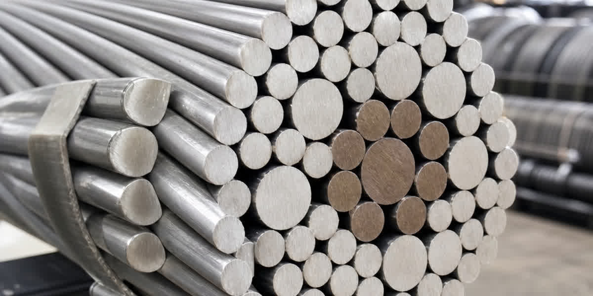
STACIR/AW conductors consist of a central invar (iron-nickel alloy) core — either as bare invar wires or aluminum-clad invar (AW) wires — surrounded by one or more layers of super thermal-resistant aluminum (ZTAL) alloy strands. The ZTAL alloy retains a high percentage of its original strength after extended exposure at 150°C–210°C, unlike conventional EC-grade aluminum which rapidly anneals above 100°C.
Construction
- Core: Invar alloy (Fe-36Ni) wires, either bare or aluminum-clad. The cladding provides galvanic compatibility with the aluminum strands.
- Conducting layer: Super thermal-resistant aluminum alloy (ZTAL) wires in concentric layers.
- Lay direction: Outer layer right-hand (RH) unless otherwise specified.
- Grease: Optional high-temperature grease between layers for corrosion mitigation in coastal or industrial environments.
Standard Specifications (STACIR/AW — Per ASTM B941)
| Code Word | Total Area (mm²) | Stranding (Al / Invar) | Overall Diameter (mm) | Rated Tensile Strength (kN) | Weight (kg/km) | DC Resistance at 20°C (Ω/km) | Current Rating at 150°C (A) | Current Rating at 210°C (A) |
|---|---|---|---|---|---|---|---|---|
| TACIR 95 | 95.0 | 12 / 7 | 12.7 | 33.2 | 375 | 0.3092 | 285 | 340 |
| TACIR 120 | 120.0 | 18 / 7 | 14.3 | 42.1 | 475 | 0.2448 | 335 | 405 |
| TACIR 150 | 150.0 | 18 / 7 | 15.9 | 52.6 | 592 | 0.1960 | 390 | 475 |
| TACIR 185 | 185.0 | 24 / 7 | 17.7 | 64.8 | 730 | 0.1590 | 450 | 545 |
| TACIR 240 | 240.0 | 30 / 7 | 20.1 | 84.0 | 947 | 0.1225 | 530 | 645 |
| TACIR 300 | 300.0 | 30 / 7 | 22.5 | 105.0 | 1,185 | 0.0980 | 615 | 750 |
| TACIR 400 | 400.0 | 30 / 19 | 26.0 | 140.0 | 1,578 | 0.0735 | 735 | 900 |
| TACIR 520 | 520.0 | 30 / 19 | 29.6 | 182.0 | 2,051 | 0.0566 | 870 | 1,065 |
| TACIR 630 | 630.0 | 54 / 19 | 32.7 | 220.5 | 2,485 | 0.0467 | 985 | 1,210 |
| TACIR 720 | 720.0 | 54 / 19 | 35.0 | 252.0 | 2,840 | 0.0408 | 1,075 | 1,325 |
💡 Selection Note: Current ratings above are based on IEEE 738 calculation assumptions: 40°C ambient, 0.61 m/s wind, 0.5 solar absorptivity, 1,000 W/m² solar radiation, 0.5 emissivity. Actual ampacity varies with site-specific conditions. For spans over 400 m or in heavy ice/wind loading zones, consult the manufacturer's sag-tension data at 150°C and 210°C before final selection.
5. STACIR/AW vs. Conventional Conductors — Comparison
The following table compares STACIR/AW against the three most common overhead conductor types across key performance parameters.
| Parameter | STACIR/AW | ACSR | ACSS | AAAC |
|---|---|---|---|---|
| Max Continuous Operating Temp | 150°C–210°C | 90°C–100°C | 200°C–250°C | 90°C–120°C |
| Sag at 150°C | ✓ Very low (invar core) | ✗ High (steel core softens) | ✓ Low (Al fully annealed) | △ Moderate |
| Rated Tensile Strength | ✓ High | ✓ High | △ Moderate | △ Moderate |
| Creep at Elevated Temp | ✓ Low | ✗ High (Al annealing) | ✓ Low (Al carries no tension) | △ Moderate |
| Corrosion Resistance (Coastal) | ✓ Excellent (Al-clad invar) | △ Moderate (galvanic cells) | △ Moderate | ✓ Excellent (homogeneous) |
| Cost Index (vs. ACSR) | 1.8–2.5× | 1.0× (baseline) | 1.3–1.6× | 1.2–1.5× |
| Typical Application | Line uprating, congestion relief, RoW-constrained | General distribution/transmission | Greenfield, long spans, high-temp zones | Coastal, industrial, moderate loads |
Symbol guide: ✓ = Best in class / excellent performance | △ = Acceptable / moderate performance | ✗ = Poor / not recommended
STACIR/AW commands a higher upfront cost than ACSR, but in reconductoring applications — where tower replacement is avoided — the total installed cost is typically 40–60% lower than building a new line. The invar core's near-zero thermal expansion translates directly into maintained ground clearance at peak load, making STACIR/AW the preferred choice when sag is the binding constraint.
6. HTLS Application Scenarios
HTLS conductors are deployed in a range of scenarios where conventional conductors cannot meet the combined requirements of high ampacity and limited sag.
| Scenario | Challenge | HTLS Solution | Benefit |
|---|---|---|---|
| Line Uprating (69 kV → 138 kV) | Existing towers lack clearance for higher voltage; new RoW difficult | Replace ACSR with STACIR/AW on same towers | Double voltage without new towers; reduced project timeline |
| Line Uprating (138 kV → 230 kV) | Insufficient clearance at high load; thermal limit binding | STACIR/AW with invar core maintains sag within limits | Capacity increase of 50–100% on existing RoW |
| Congestion Relief | Transmission line thermally limited; frequent curtailment of renewables | Reconductoring with HTLS increases thermal limit | Reduced curtailment; higher renewable integration |
| RoW Constraints | No available land for parallel circuits; environmental restrictions | Upgrade existing circuit with HTLS | Maximum capacity from existing corridor |
| Reconductoring Aged Lines | ACSR conductors degraded (corrosion, fatigue, Al annealing) | Replace with STACIR/AW | Extended service life + capacity increase in one operation |
| New Greenfield Corridors | Long span requirements (river crossings, mountainous terrain); future-proofing | Design with STACIR/AW from the start | Higher initial capacity; reduced future upgrade costs |
7. Selection Methodology
Selecting the correct STACIR/AW conductor for a project follows a systematic five-step process.
Step 1: Define Electrical Requirements
Determine the target ampacity based on load growth projections, generation interconnection requirements, or N-1 contingency needs.
| Parameter | Typical Values | Notes |
|---|---|---|
| Voltage class | 69 kV / 138 kV / 230 kV / 400 kV | Determines insulation coordination |
| Target ampacity (A) | 600–1,500 A | Based on 10–20 year load forecast |
| Power transfer (MVA) | 100–600 MVA | S = √3 × V × I |
| Voltage drop limit | 3–5% | Per utility planning criteria |
Step 2: Select HTLS Type
Based on sag constraints, operating temperature, and environmental conditions, select the HTLS variant. Use the comparison table in Section 5 as a guide.
- Sag-limited upgrade: STACIR/AW or ACSS/AW
- Temperature-limited upgrade (existing hardware rated ≤150°C): STACIR/AW (150°C)
- Corrosive environment (coastal, industrial): STACIR/AW with aluminum-clad invar core
- Long span / river crossing: ACCR or STACIR/AW with verified creep data
Step 3: Check Thermal Rating (Ampacity)
Calculate ampacity at the selected operating temperature using IEEE 738 or IEC 61597.
I = √[(Q_rad + Q_conv - Q_solar) / R(T)]
Where: - Q_rad = radiative heat loss (W/m) - Q_conv = convective heat loss (W/m) - Q_solar = solar heat gain (W/m) - R(T) = conductor resistance at operating temperature T (Ω/m)
💡 Quick Rule: For preliminary sizing, STACIR/AW at 150°C carries approximately 1.6–1.8× the ampacity of the same-sized ACSR at 75°C. At 210°C, this increases to 1.9–2.2×.
Step 4: Verify Clearance and Sag
Sag at the maximum design temperature must comply with regulatory ground clearance requirements (NESC, IEC, or local code). Use CIGRE TB 324 methods.
| Check | STACIR/AW (invar core) | ACSR (steel core) |
|---|---|---|
| CTE of core material | ~3 × 10⁻⁶/°C | ~11.5 × 10⁻⁶/°C |
| Sag at 150°C (typical 300m span) | ~4.5 m | ~7.2 m |
| Sag at 210°C (typical 300m span) | ~5.1 m | Not permitted |
| Clearance maintained? | ✓ Yes (within limits) | ✗ No (violates NESC) |
Step 5: Evaluate Economic Options
Perform a life-cycle cost (LCC) analysis comparing STACIR/AW against the next-best alternative.
| Cost Component | STACIR/AW | ACSR (new line) | ACSS (reconductoring) |
|---|---|---|---|
| Conductor material cost | 1.8–2.5× ACSR | 1.0× (baseline) | 1.3–1.6× ACSR |
| Tower modification cost | None (reconductoring) | 3–5× baseline (new towers) | None |
| Installation cost | 1.1–1.3× ACSR | 2.0–3.0× (new construction) | 1.0–1.2× ACSR |
| Losses (20-year NPV) | Lower (larger Al area) | Baseline | Similar to ACSR |
| Maintenance cost | Comparable to ACSR | Baseline | Comparable |
| Total LCC (20 years) | 1.2–1.6× ACSR | 2.5–4.0× ACSR (new line) | 1.0–1.4× ACSR |
Where tower replacement is avoided — which is the primary business case for HTLS — STACIR/AW delivers the lowest total LCC of any capacity-upgrade solution.
8. Installation Considerations
Installing STACIR/AW conductors requires attention to several factors that differ from conventional ACSR installation.
Stringing Tension Limits
STACIR/AW conductors should be strung at tensions not exceeding 15–20% of the rated tensile strength (RTS) at ambient temperature, with a maximum allowable tension of 25% RTS during pulling. The final installed tension at 15°C (initial, without creep) is typically 15–18% RTS.
| Parameter | Recommendation | Rationale |
|---|---|---|
| Maximum pulling tension | 25% RTS | Avoid permanent core deformation |
| Final installed tension (15°C) | 15–18% RTS | Ensures adequate clearance at max temp |
| Minimum stringing temperature | 0°C | Below this, increased vibration risk |
Hardware Compatibility
All line hardware — dead-ends, splices, jumper terminals, and vibration dampers — must be rated for the conductor's maximum continuous operating temperature (150°C–210°C).
| Hardware Component | Temperature Rating Required | Notes |
|---|---|---|
| Compression dead-ends | ≥210°C | Use stainless steel or Al-bronze sleeves |
| Full-tension splices | ≥210°C | Two-step compression (core + Al) |
| Bolted connectors | ≥150°C | Belleville washers to maintain contact pressure |
| Armor rods | ≥210°C | Same alloy as conductor |
| Vibration dampers | ≥150°C | Elastomer type must withstand sustained high temp |
Vibration Mitigation
The high operating tension of HTLS conductors increases aeolian vibration susceptibility. Stockbridge-type dampers or spiral vibration dampers are recommended at all line terminations and at suspension points on spans exceeding 200 m.
Compression vs. Bolted Connectors
- Compression connectors (two-stage: core compression first, then aluminum barrel) are mandatory for full-tension splices and dead-ends rated above 50% RTS.
- Bolted connectors may be used for jumper terminals and substation connections at lower tensions, but must include Belleville spring washers to compensate for differential thermal expansion between aluminum and steel hardware at elevated temperatures.
9. Environmental & Durability Considerations
The long-term performance of STACIR/AW conductors depends on proper material selection and installation practices matched to the site environment.
| Factor | Recommendation | Rationale |
|---|---|---|
| Coastal corrosion | Specify aluminum-clad invar (AW) core wires | Eliminates galvanic corrosion between core and Al strands; cladding thickness per ASTM B941 |
| Industrial pollution | Apply high-temperature corrosion-inhibiting grease between layers | Prevents ingress of SO₂, NOₓ, and chloride compounds into inter-strand crevices |
| Ice loading | Use STACIR/AW at 15–18% RTS EDS | Higher initial tension reduces ice-induced sag; invar core maintains clearance after ice shedding |
| UV radiation | Standard ZTAL aluminum alloy has natural UV resistance | No protective coating required; UV does not degrade aluminum strands |
| High ambient temp | Derate ampacity per IEEE 738 using site-specific max ambient | Continuous operation at 150°C+ requires correct weather assumptions |
💡 Durability Note: The invar core in STACIR/AW does not corrode sacrificially like galvanized steel core wires. In coastal environments with airborne chlorides, STACIR/AW with aluminum-clad invar core offers significantly longer service life than standard ACSR, often exceeding 50 years with proper hardware selection.
10. Case Study — 138 kV Line Uprating: ACSR Drake to STACIR/AW
Project Background
A utility operating a 138 kV transmission line in a coastal region experienced increasing congestion due to load growth from a nearby industrial zone. The line is 50 km long, originally built with ACSR Drake (795 kcmil, 26/7 stranding) on lattice steel towers. Regulatory ground clearance of 7.0 m at maximum operating temperature could not be violated.
Options Evaluated
| Parameter | Existing: ACSR Drake | Option A: STACIR/AW 400 | Option B: New Parallel Line |
|---|---|---|---|
| Conductor type | ACSR 795 kcmil 26/7 | STACIR/AW 400 mm² | ACSR Drake (new circuit) |
| Total Al area | 403 mm² | 400 mm² | 403 mm² |
| Max operating temp | 90°C | 150°C | 90°C |
| Ampacity (continuous) | 835 A | 1,280 A (150°C) | 835 A |
| Total capacity (MVA) | 200 MVA | 306 MVA | 200 MVA |
| Sag at max temp (critical span) | 8.1 m (90°C) | 4.9 m (150°C) | 8.1 m (90°C) |
| Clearance violation? | Yes, if uprated to 150°C | No (7.0 m maintained) | N/A (new RoW) |
| Tower modifications required | None | None | New towers needed |
| Estimated project cost | — | $4.2M USD | $15.8M USD |
| Construction timeline | — | 10 months | 36 months |
| RoW acquisition | — | None required | 50 km new corridor |
Recommendation
Option A — Reconductoring with STACIR/AW 400 mm² — was selected. The project delivered a 53% ampacity increase (from 835 A to 1,280 A) using the existing tower structures with zero clearance violations at the design temperature. Compared to building a new parallel line, the STACIR/AW solution saved approximately $11.6M USD in capital expenditure and avoided 26 months of project timeline. The line has been in service for 18 months with no sag-related issues reported.
11. FAQ
Q1: What is the expected service life of HTLS conductors compared to ACSR?
STACIR/AW conductors have an expected service life of 40–50 years, comparable to or exceeding standard ACSR (35–45 years). The invar core does not suffer from galvanic corrosion in coastal environments, and the ZTAL aluminum alloy retains mechanical strength at elevated temperatures far better than EC-grade aluminum used in ACSR.
Q2: Can STACIR/AW be installed on existing towers without modifications?
Yes — this is the primary business case for HTLS. STACIR/AW conductors are designed to have the same or smaller diameter and similar weight to the ACSR conductors they replace, allowing direct installation on existing towers. Tower load verification (compression, tension, and wind loading) is always recommended but modifications are rarely required.
Q3: What temperature rating do splice and dead-end hardware need?
All hardware must be rated for at least the conductor's maximum continuous operating temperature. For STACIR/AW operating at 150°C, hardware rated to 180°C is recommended. For 210°C operation, hardware rated to 240°C or higher is required. Standard ACSR hardware (rated 90°C) must never be used.
Q4: How does the invar core reduce sag compared to a steel core?
Invar (Fe-36Ni alloy) has a coefficient of thermal expansion (CTE) of approximately 3 × 10⁻⁶/°C, roughly one-quarter of steel's 11.5 × 10⁻⁶/°C. When the conductor temperature rises, the invar core expands much less than a steel core, so the conductor sags significantly less. At 150°C, a STACIR/AW conductor on a 300 m span will sag roughly 35–40% less than an equivalent ACSR conductor.
Q5: What is the maximum span length for STACIR/AW conductors?
Span lengths of 300–500 m are typical for STACIR/AW in transmission applications. Longer spans (up to 800 m for river crossings) are possible with larger code words (TACIR 400 and above) and reduced design tensions. For spans exceeding 600 m, a custom sag-tension analysis considering creep, ice loading, and dynamic ampacity is essential.
Q6: Can STACIR/AW be spliced with standard hydraulic compression tools?
Yes — STACIR/AW splices use the same two-stage compression process as ACSR (core splice first, then aluminum barrel). Standard 60–150 ton hydraulic tools with appropriate dies are suitable. The key difference is that splice bodies must be rated for the higher operating temperature, typically using stainless steel or aluminum-bronze for the core sleeve instead of galvanized steel.
Q7: What is the cost premium of STACIR/AW compared to standard ACSR?
The material cost of STACIR/AW is approximately 1.8–2.5× that of equivalent-sized ACSR. However, when evaluating total project cost for a reconductoring project, the STACIR/AW solution typically costs 60–80% less than building a new line, because tower replacement and new RoW acquisition are avoided. On a life-cycle cost basis including losses, STACIR/AW is competitive with ACSR for high-load applications.
Q8: How are STACIR/AW conductors inspected in service?
Standard infrared thermography (splice and dead-end inspection) applies, but must be scheduled during high-load periods when the conductor is at elevated temperature. Aeolian vibration monitoring (if installed) should be reviewed quarterly during the first year of service. Sag measurements via LiDAR or GPS survey are recommended annually for the first three years to validate creep stabilization, then every five years thereafter.
12. Conclusion
STACIR/AW conductors offer a proven, standards-backed solution for transmission line capacity upgrades where sag constraints prevent the use of conventional ACSR conductors. The invar core's low thermal expansion coefficient enables continuous operation at 150°C–210°C while maintaining regulatory ground clearances — a combination that no conventional conductor can match. For utilities facing congestion, load growth, or renewable integration challenges on constrained rights-of-way, STACIR/AW reconductoring delivers significant capacity gains at a fraction of the cost and timeline of new line construction.
At SiTong Cable, we manufacture STACIR/AW conductors to ASTM B941 and IEC 61089 standards, with full tensile testing, resistance measurement, and sag-tension data available for each production lot. Our engineering team supports customers with conductor selection, sag-tension calculations, and hardware compatibility reviews for projects worldwide.
👉 Browse our ACSR conductors 👉 Browse our AAAC conductors 👉 Browse our AAC conductors 👉 Contact our engineering team
📬 Sales inquiries: sales@sitongcable.com | 📞 Phone: +86-371-69176007
This guide was prepared by the SiTong Cable engineering team. All technical data references IEEE 738, IEC 61089, ASTM B941, ASTM B856, ASTM B857, CIGRE TB 244, CIGRE TB 324, and IEC 61597.