Underground Cable Ampacity Calculation & Thermal Backfill Guide: IEC 60287, Neher-McGrath & Soil Resistivity
Underground Cable Ampacity Calculation & Thermal Backfill Guide: IEC 60287, Neher-McGrath & Soil Resistivity
Master underground cable ampacity calculation using IEC 60287 and Neher-McGrath methods. Learn soil thermal resistivity modeling, duct bank derating, and FTB design.
1. Introduction: The Thermodynamic Reality of Underground Power Delivery
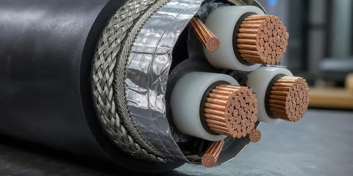
When transitioning transmission and distribution circuits from overhead lines to subterranean infrastructure, the fundamental limiting factor shifts dramatically from aerodynamic convective cooling to solid-state conductive heat dissipation. In an overhead line, heat generated by Joule losses ($I^2R$) is continuously dissipated into the ambient atmosphere via natural wind convection and radiation. In contrast, buried underground power cables are encapsulated within solid dielectric insulation, metallic screens, protective jackets, and surrounding backfill materials, all situated in geological soil with significantly higher thermal resistivity.
Operating an underground circuit beyond its thermodynamic equilibrium elevates conductor temperature beyond permissible continuous design limits—typically 90°C for cross-linked polyethylene (XLPE) and ethylene propylene rubber (EPR), or 70°C for polyvinyl chloride (PVC). Sustained overheating accelerates thermal degradation of the polymer insulation, induces dielectric loss breakdown, provokes moisture migration in surrounding soil, and can trigger catastrophic thermal runaway.
Accurate determination of continuous current-carrying capacity (ampacity) and cyclic emergency ratings requires rigorous mathematical modeling of the multi-layer thermal resistance network between the energized conductor and the ambient earth. This engineering guide details the analytical frameworks of IEC 60287 and the Neher-McGrath method, evaluates soil thermal resistivity dynamics, establishes grouping derating factors for duct banks and trenches, and outlines the mix design and performance specifications of Fluidized Thermal Backfill (FTB).
   +-------------------------------------------------------------+
   |                  THERMAL RESISTANCE LADDER                  |
   |                                                             |
   |   Conductor (Joule Heat: I²R + Dielectric Loss Wd)          |
   |       |                                                     |
   |     [ T1 ]  Insulation & Semi-Conductive Screen             |
   |       v                                                     |
   |   Metallic Sheath / Screen (Loss Factor: λ1)                |
   |       |                                                     |
   |     [ T2 ]  Bedding / Inner Sheath                          |
   |       v                                                     |
   |   Armor Layer (Loss Factor: λ2)                             |
   |       |                                                     |
   |     [ T3 ]  Outer Protective Jacket (PE / PVC)              |
   |       v                                                     |
   |   Cable Surface                                             |
   |       |                                                     |
   |     [ T4 ]  Duct Air Gap / Thermal Backfill / Native Soil   |
   |       v                                                     |
   |   Undisturbed Ambient Earth (Base Temperature θ_amb)        |
   +-------------------------------------------------------------+
2. Analytical Rating Methodologies: IEC 60287 vs. Neher-McGrath
Two primary analytical standards govern modern underground cable ampacity calculations: the international standard IEC 60287 series (widely adopted throughout Europe, Asia, Africa, and Latin America) and the North American Neher-McGrath method (formalized in IEEE Std 835 and embedded within NFPA 70 / NEC Article 310).
2.1 The IEC 60287 Thermal Resistance Network
The IEC 60287 standard calculates continuous steady-state current capacity by modeling the cable and its environment as an electrical equivalent ladder network, applying Fourier's law of thermal conduction. For a three-conductor cable or three single-core medium voltage power cables carrying identical continuous alternating currents, the permissible current $I$ (in Amperes) is given by:
$$I = \left[ \frac{\Delta \theta - W_d [0.5 T_1 + n(T_2 + T_3 + T_4)]}{R_{ac} T_1 + n R_{ac} (1 + \lambda_1) T_2 + n R_{ac} (1 + \lambda_1 + \lambda_2)(T_3 + T_4)} \right]^{0.5}$$
Where: * $\Delta \theta = \theta_c - \theta_a$: Permissible conductor temperature rise above ambient earth (°C). For XLPE, $\theta_c = 90^\circ\text{C}$; if $\theta_a = 25^\circ\text{C}$, $\Delta \theta = 65\text{ K}$. * $R_{ac}$: Alternating current electrical resistance of the conductor per unit length at maximum operating temperature $\theta_c$ ($\Omega/\text{m}$), accounting for skin effect ($y_s$) and proximity effect ($y_p$). * $W_d$: Dielectric power loss per unit length in the insulation ($\text{W/m}$), determined by operating voltage $U_0$, capacitance $C$, and dielectric loss factor $\tan \delta$. * $T_1$: Thermal resistance per unit length between conductor and metallic sheath/screen ($\text{K}\cdot\text{m/W}$). * $T_2$: Thermal resistance per unit length between metallic sheath and armor ($\text{K}\cdot\text{m/W}$). * $T_3$: Thermal resistance per unit length of the external protective outer jacket ($\text{K}\cdot\text{m/W}$). * $T_4$: External thermal resistance between cable outer surface and surrounding undisturbed soil ($\text{K}\cdot\text{m/W}$), integrating duct air gaps, backfill, and native soil isotherms. * $n$: Number of current-carrying conductors in the cable ($n=1$ for single-core, $n=3$ for three-core). * $\lambda_1$: Ratio of circulating and eddy current losses in the metallic sheath/screen to total conductor losses. * $\lambda_2$: Ratio of losses in the armor layer to total conductor losses.
2.2 The Neher-McGrath Formulation (IEEE 835 / NEC)
Published in 1957 by J.H. Neher and M.H. McGrath, this methodology utilizes an empirical approach to solve heat transfer equations for cables in underground duct banks, conduits, and direct buried configurations. The classic formulation is expressed as:
$$I = \sqrt{\frac{T_c - (T_a + \Delta T_d)}{R_{dc} (1 + Y_c) R_{ca}'}}$$
Where: * $T_c$: Maximum conductor operating temperature (°C). * $T_a$: Ambient earth temperature (°C). * $\Delta T_d$: Temperature rise attributable to dielectric loss (°C). * $R_{dc}$: Direct-current electrical resistance of the conductor at temperature $T_c$ ($\mu\Omega/\text{ft}$). * $Y_c$: Component factor accounting for AC skin effect, proximity effect, sheath currents, and magnetic conduit losses. * $R_{ca}'$: Effective thermal resistance between conductor and ambient earth ($\text{thermal-ohm-ft}$), incorporating internal thermal resistances and the mutual heating factor of adjacent energized conduits.
2.3 Technical Comparison
| Engineering Parameter | IEC 60287-1-1 / IEC 60287-2-1 | Neher-McGrath / IEEE Std 835 |
|---|---|---|
| Primary Scope | International (IEC, BS, DIN, EN) | North American (IEEE, ICEA, NEC) |
| Loss Modeling | Explicit component calculation ($\lambda_1, \lambda_2, W_d$) | Lumped factor formulation ($Y_c, \Delta T_d$) |
| Duct Bank Modeling | Kennelly's formula + numerical image method | Empirical geometry factors & duct multipliers |
| Non-Uniform Soil Layers | Multi-zone thermal resistance equations | Thermal superposition / finite difference |
| Dynamic / Transient Rating | Covered under IEC 60853-1/2/3 | Covered under CIGRE WG B1 & IEEE 442 |
| Applicability to Modern Cables | Milliken conductors, laminated sheaths, TR-XLPE | Standard concentric stranded conductors |
3. Soil Thermal Resistivity ($\rho_s$) and Moisture Migration Dynamics
The external thermal resistance $T_4$ typically accounts for 50% to 70% of the total thermal impedance in an underground installation. Consequently, the thermal resistivity of the surrounding soil matrix ($\rho_s$, expressed in $\text{K}\cdot\text{m/W}$ or $^\circ\text{C}\cdot\text{cm/W}$, where $1.0\text{ K}\cdot\text{m/W} = 100^\circ\text{C}\cdot\text{cm/W}$) is the single most critical variable dictating cable ampacity.
3.1 Soil Composition and Baseline Thermal Properties
Soil thermal conductivity operates via solid particle contact conduction and pore fluid convection. As air has an exceptionally high thermal resistivity ($\rho \approx 40.0\text{ K}\cdot\text{m/W}$), porous, uncompacted, or dry soils create massive thermal bottlenecks.
| Soil / Material Classification | Typical Moisture Content (%) | Dry Density ($\text{g/cm}^3$) | Thermal Resistivity $\rho_s$ ($\text{K}\cdot\text{m/W}$) |
|---|---|---|---|
| Saturated Clay / Silt | 25% – 35% | 1.4 – 1.6 | 0.60 – 0.80 |
| Moist Sandy Loam | 10% – 15% | 1.6 – 1.8 | 0.90 – 1.20 |
| Dry Coarse Sand (Uncompacted) | 1% – 3% | 1.4 – 1.5 | 2.00 – 3.00 |
| Gravel / Crushed Rock | 0% – 2% | 1.5 – 1.7 | 1.80 – 2.50 |
| Standard Native Earth (IEC Default) | 8% – 12% | 1.6 – 1.7 | 1.00 |
| North American Standard Design | Seasonally variable | Variable | 0.90 (Wet) / 1.20 (Dry) |
| Fluidized Thermal Backfill (FTB) | Saturated to bone-dry | 1.9 – 2.2 | 0.50 (Wet) / 0.85 (Dry) |
| Concrete (Standard Encasement) | Standard cured | 2.2 – 2.4 | 0.80 – 1.00 |
3.2 The Two-Zone Model and Thermal Runaway
When underground cables operate under continuous high load, the radial temperature gradient drives moisture away from the hot cable surface toward cooler ambient soil zones—a thermodynamic phenomenon known as moisture migration.
   +---------------------------------------------------------------+
   |               TWO-ZONE SOIL DRYOUT PHENOMENON                 |
   |                                                               |
   |     +-------------------+                                     |
   |     | Cable (θ_surf)    |                                     |
   |     +---------+---------+                                     |
   |               |                                               |
   |   [ DRY ZONE: ρ_dry = 2.5 K·m/W ] <--- Moisture vaporizes &   |
   |   | High thermal impedance      |      migrates outwards      |
   |   +---------------+-------------+                             |
   |                   | Critical Boundary (θ_crit ≈ 50°C - 60°C)  |
   |   [ WET ZONE: ρ_wet = 1.0 K·m/W ] <--- Undisturbed moisture   |
   |   | Retains normal conductivity |                             |
   |   +-----------------------------+                             |
   +---------------------------------------------------------------+
If the heat flux at the cable surface exceeds the soil's critical moisture retention threshold (typically corresponding to a cable surface temperature above 50°C–60°C in sandy soils), a localized dryout zone develops immediately adjacent to the cable: 1. The soil in the dryout zone loses pore water, causing thermal resistivity to jump from $\approx 1.0\text{ K}\cdot\text{m/W}$ to $\ge 2.5\text{ K}\cdot\text{m/W}$. 2. The increased external thermal resistance $T_4$ raises conductor operating temperature for the same current load. 3. Higher conductor temperature further accelerates moisture vaporization and expands the dry zone boundary. 4. Thermal Runaway: The continuous feedback loop rapidly escalates conductor temperature beyond 90°C, causing dielectric softening, insulation breakdown, and irreversible cable failure.
To prevent thermal instability, engineers must implement either conservative ampacity derating based on the IEC two-zone model ($\rho_{\text{dry}} = 2.5\text{ K}\cdot\text{m/W}$) or specify engineered thermal backfills.
4. Fluidized Thermal Backfill (FTB): Engineering Specification & Mix Design
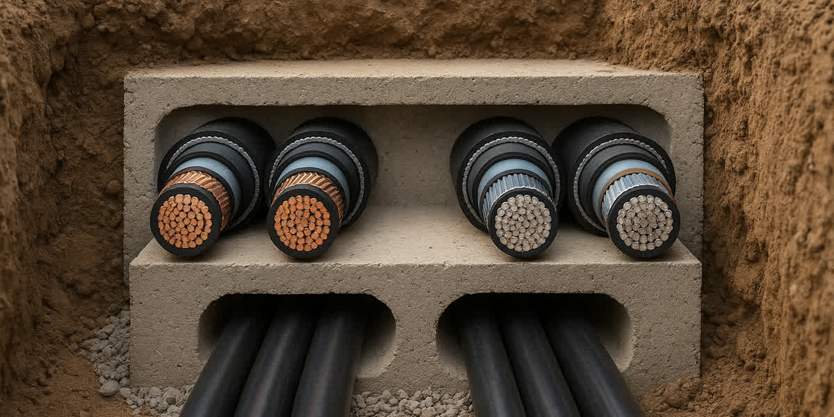
Fluidized Thermal Backfill (FTB™) is a specialized low-strength, high-density slurry comprising mineral aggregates, sand, fly ash, Portland cement, and water. It is designed to be poured directly around direct-buried cables or underground duct banks.
   +-------------------------------------------------------------+
   |             ENGINEERED TRENCH PROFILE WITH FTB              |
   |                                                             |
   |   ================ Final Ground Surface =================   |
   |   [ Native Soil Backfill (Compacted)                     ]  |
   |   -------------------------------------------------------   |
   |   [ Underground Warning Tape / Warning Board            ]   |
   |   -------------------------------------------------------   |
   |   +-----------------------------------------------------+   |
   |   | FLUIDIZED THERMAL BACKFILL (FTB) ENCASEMENT         |   |
   |   |                                                     |   |
   |   |     ( O ) Cable A     ( O ) Cable B     ( O ) Cable C |   |
   |   |                                                     |   |
   |   |   Min 150 mm Envelope Around All Phase Conductors   |   |
   |   +-----------------------------------------------------+   |
   |   ================ Trench Base Bedding ==================   |
   +-------------------------------------------------------------+
4.1 FTB Mix Design Parameters
The thermal and mechanical properties of FTB are precisely balanced to achieve low thermal resistivity in both wet and completely desiccated states, while maintaining low compressive strength for future excavation:
- Well-Graded Natural Aggregate & Sand (65% – 75% by volume): Maximizes grain-to-grain contact points to establish a continuous conduction pathway even when 100% dry.
- Fly Ash / Pozzolan (15% – 20%): Lubricates the mix for high self-leveling fluidity (slump $\ge 200\text{ mm}$), completely eliminating air voids around cable outer sheaths.
- Portland Cement (3% – 5%): Provides slight structural cohesion to prevent post-curing settlement without excessive hardening.
- Water-to-Solids Ratio: Optimized to achieve fluid placement without aggregate segregation.
4.2 Engineering Specification Table for Thermal Backfill
| Performance Metric | Test Standard | Native Sandy Clay | Standard Concrete | Engineered FTB |
|---|---|---|---|---|
| Wet Thermal Resistivity ($\rho_{\text{wet}}$) | IEEE Std 442 / ASTM D5334 | $0.90 - 1.20\text{ K}\cdot\text{m/W}$ | $0.80 - 0.90\text{ K}\cdot\text{m/W}$ | $\le 0.50\text{ K}\cdot\text{m/W}$ |
| Completely Dry Resistivity ($\rho_{\text{dry}}$) | IEEE Std 442 (Dried at 105°C) | $2.20 - 3.50\text{ K}\cdot\text{m/W}$ | $1.20 - 1.50\text{ K}\cdot\text{m/W}$ | $\le 0.85\text{ K}\cdot\text{m/W}$ |
| 28-Day Compressive Strength | ASTM D4832 / EN 12390-3 | N/A | $15 - 25\text{ MPa}$ | $0.5 - 1.5\text{ MPa}$ (Excavatable) |
| Flowability / Slump | ASTM D6103 | Variable | $100 - 150\text{ mm}$ | $\ge 200\text{ mm}$ (Self-Leveling) |
| Air Void Content | ASTM C138 | $15% - 25%$ | $4% - 8%$ | $\le 2.0\%$ |
| Relative Ampacity Gain | IEC 60287 Calculation | Baseline (1.00) | $+8\% \text{ to } +12\%$ | $+18\% \text{ to } +28\%$ |
Utilizing FTB allows utility transmission lines and solar/wind collector feeder systems to increase continuous current throughput by up to 25% without upsizing conductor cross-sectional area, yielding substantial capital savings on high-purity electrolytic copper or aluminum conductor materials.
5. Mutual Heating & Grouping Derating: Direct Burial vs. Duct Banks
When multiple power circuits share a common trench, tunnel, or concrete duct bank, the thermal fields generated by adjacent energized conductors superimpose, creating mutual heating. This elevates the external temperature $T_4$ for each individual cable and mandates derating factors ($F_g$).
   DIRECT-BURIED FLAT / TREFOIL              CONCRETE-ENCASED DUCT BANK (3x3 ARRAY)
   +----------------------------+            +------------------------------------+
   |   ( A )    ( B )    ( C )  |            |   [ (1) ]     [ (2) ]     [ (3) ]  |
   |   <---- S ----><---- S ---->|            |                                    |
   | Single Layer: Clear Thermal|            |   [ (4) ]     [ (5) ]*    [ (6) ]  |
   | Path to Surface            |            |               *Hottest Conduit     |
   +----------------------------+            |   [ (7) ]     [ (8) ]     [ (9) ]  |
                                             +------------------------------------+
5.1 Mutual Heating Calculation (Superposition Principle)
Under IEC 60287-2-1, the external thermal resistance of a group of $q$ identical parallel buried cables is calculated using Kennelly's formula and the method of thermal images:
$$T_4 = \frac{\rho_s}{2\pi} \left[ \ln\left(\frac{2u}{d_e} + \sqrt{\left(\frac{2u}{d_e}\right)^2 - 1}\right) + \sum_{k=1}^{q-1} \ln\left(\frac{d_{p,k}'}{d_{p,k}}\right) \right]$$
Where: * $u$: Burial depth of the cable axis below ground surface ($\text{mm}$). * $d_e$: External overall diameter of the cable ($\text{mm}$). * $d_{p,k}$: Physical distance from the reference cable $p$ to adjacent cable $k$ ($\text{mm}$). * $d_{p,k}'$: Distance from reference cable $p$ to the fictional thermal mirror image of cable $k$ mirrored across the ground surface ($\text{mm}$).
5.2 Grouping Derating Factors Table
The following table summarizes grouping correction factors ($F_g$) applied to base continuous ampacity for multi-circuit 3-phase systems buried at standard depth ($u = 1.0\text{ m}$, $\rho_s = 1.0\text{ K}\cdot\text{m/W}$, continuous load factor = 100%):
| Laying Configuration | Number of 3-Phase Circuits | Clearance / Spacing | Derating Factor $F_g$ (Touching) | Derating Factor $F_g$ (Spacing = 150 mm) | Derating Factor $F_g$ (Spacing = 300 mm) |
|---|---|---|---|---|---|
| Direct Buried (Trefoil Formation) | 1 Circuit (3x1C) | N/A | 1.00 | 1.00 | 1.00 |
| Direct Buried (Trefoil Formation) | 2 Circuits (6x1C) | $S$ | 0.78 | 0.84 | 0.89 |
| Direct Buried (Trefoil Formation) | 3 Circuits (9x1C) | $S$ | 0.68 | 0.75 | 0.82 |
| Direct Buried (Trefoil Formation) | 4 Circuits (12x1C) | $S$ | 0.61 | 0.70 | 0.77 |
| Direct Buried (Flat Formation) | 1 Circuit (3x1C) | $S = d_e$ | 0.93 | 0.97 | 1.00 |
| Direct Buried (Flat Formation) | 2 Circuits (6x1C) | $S = d_e$ | 0.72 | 0.80 | 0.86 |
| Underground Duct Bank (2x2 Conduit) | 4 Circuits | Enclosed | 0.65 | 0.72 | 0.78 |
| Underground Duct Bank (3x3 Conduit) | 6 to 8 Circuits | Enclosed | 0.52 | 0.59 | 0.66 |
Note: In a 3x3 concrete duct bank, the center conduit (position 5) suffers the most severe mutual heating, requiring the entire bank rating to be governed by the thermal bottleneck of the central position unless circuit loading is staggered.
For critical grounding grid installations in dense substations, high fault current dissipation must be maintained alongside power feeder banks. Utilizing galvanized steel wire strands and dedicated earth conductors ensures robust fault ride-through capability without compromising surrounding soil thermal integrity.
6. Comprehensive Ampacity & Derating Reference Table
The following engineering reference table presents continuous current ratings for copper and aluminum conductor XLPE insulated medium voltage cables (11kV to 33kV, single-core, copper tape screen, unarmored/armored, IEC 60502-2), calculated under base reference conditions: ground temperature $\theta_a = 20^\circ\text{C}$, conductor temperature $\theta_c = 90^\circ\text{C}$, burial depth $u = 0.8\text{ m}$, soil thermal resistivity $\rho_s = 1.0\text{ K}\cdot\text{m/W}$.
| Conductor Size ($\text{mm}^2$) | Conductor Material | Trefoil Formation (Direct Buried) [A] | Flat Formation (Direct Buried, $S=70\text{mm}$) [A] | Duct Bank (Single Conduit per Phase) [A] | Resistance $R_{ac}$ @ 90°C ($\Omega/\text{km}$) |
|---|---|---|---|---|---|
| $70\text{ mm}^2$ | Copper (Cu) | 265 | 280 | 240 | 0.342 |
| $70\text{ mm}^2$ | Aluminum (Al) | 205 | 215 | 185 | 0.568 |
| $120\text{ mm}^2$ | Copper (Cu) | 355 | 380 | 320 | 0.196 |
| $120\text{ mm}^2$ | Aluminum (Al) | 275 | 290 | 245 | 0.325 |
| $240\text{ mm}^2$ | Copper (Cu) | 510 | 555 | 450 | 0.098 |
| $240\text{ mm}^2$ | Aluminum (Al) | 395 | 425 | 350 | 0.162 |
| $400\text{ mm}^2$ | Copper (Cu) | 650 | 715 | 560 | 0.062 |
| $400\text{ mm}^2$ | Aluminum (Al) | 510 | 555 | 435 | 0.102 |
| $630\text{ mm}^2$ | Copper (Cu) | 795 | 880 | 670 | 0.043 |
| $630\text{ mm}^2$ | Aluminum (Al) | 630 | 690 | 530 | 0.072 |
| $800\text{ mm}^2$ (Milliken) | Copper (Cu) | 885 | 990 | 740 | 0.034 |
| $1000\text{ mm}^2$ (Milliken) | Copper (Cu) | 975 | 1100 | 805 | 0.028 |
When terminating high-cross-section copper and aluminum power conductors into switchgear or transformers, selecting precision-machined, high-conductivity cable lugs and compression terminals is essential to prevent localized joint overheating. Furthermore, robust mechanical anchoring with certified power cable hardware and cleats restrains severe electromagnetic forces during short-circuit faults.
7. Step-by-Step Engineering Selection & Calculation Workflow
To ensure dependable underground cable sizing that balances thermal safety and economic optimization, electrical project engineers should execute the following systematic procedure:
+-------------------------------------------------------------------------+
|                  STEP-BY-STEP AMPACITY SIZING PROCESS                   |
|                                                                         |
|  [Step 1: Geotechnical Survey] -> In-situ thermal needle probe test     |
|                                   (IEEE 442) to establish ρ_s & θ_amb   |
|                                                                         |
|  [Step 2: Circuit Routing]     -> Trench profile, duct bank layout,     |
|                                   depth of lay, and circuit spacing     |
|                                                                         |
|  [Step 3: Preliminary Sizing]  -> Select conductor cross-section via    |
|                                   steady-state base ampacity tables     |
|                                                                         |
|  [Step 4: Derating Analysis]   -> Apply correction factors:             |
|                                   I_actual = I_base * F_temp * F_soil   |
|                                              * F_depth * F_group        |
|                                                                         |
|  [Step 5: Thermal Simulation]  -> IEC 60287 ladder network evaluation;  |
|                                   verify dryout zone & FTB envelope     |
|                                                                         |
|  [Step 6: Short-Circuit Check] -> Adiabatic thermal withstand check     |
|                                   for conductor and metallic screen     |
+-------------------------------------------------------------------------+
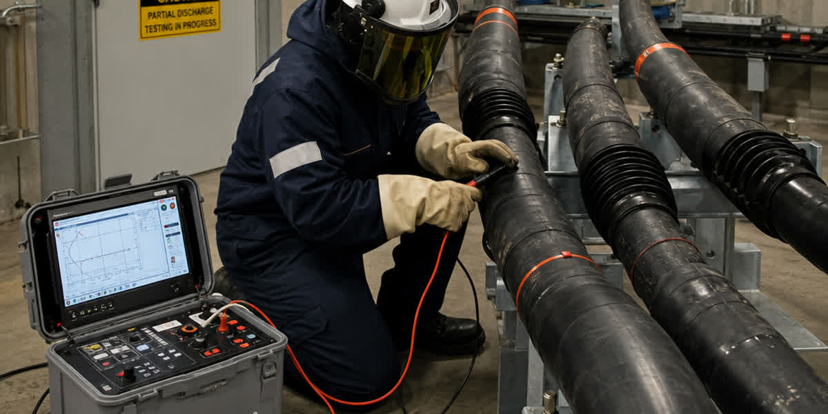
- Conduct In-Situ Geotechnical Thermal Measurements: Never rely on nominal handbook estimates for major infrastructure. Deploy thermal needle probes according to IEEE Std 442 / ASTM D5334 during dry seasonal periods to determine baseline in-situ thermal resistivity ($\rho_s$) and undisturbed ambient temperature ($\theta_a$).
- Define Installation Geometry & Circuit Architecture: Establish laying depth ($u$), horizontal/vertical center-to-center spacing ($S$), phase arrangement (trefoil vs. flat formation), and metallic sheath bonding scheme (single-point bonded, both-ends bonded, or cross-bonded).
- Execute Base Rating and Derating Calculation: Calculate the actual allowable operating ampacity ($I_{\text{rated}}$) using consolidated correction factors: $$I_{\text{rated}} = I_{\text{base}} \times F_{\text{temp}} \times F_{\text{soil}} \times F_{\text{depth}} \times F_{\text{group}}$$
- Perform Critical Heat Flux & Dryout Boundary Verification: Check if cable outer jacket temperature exceeds the critical moisture migration limit ($\theta_{\text{crit}} \approx 55^\circ\text{C}$). If exceeded, redesign the trench profile with a 150–300 mm Fluidized Thermal Backfill envelope or increase conductor cross-sectional area.
- Verify Short-Circuit Thermal Capacity: Confirm that the conductor and metallic copper tape screen withstand system prospective short-circuit currents without exceeding adiabatic thermal limits ($250^\circ\text{C}$ for XLPE insulation, $350^\circ\text{C}$ for semi-conductive screens under IEC 60949).
- Incorporate Control & Auxiliary Infrastructure: Route auxiliary control and instrumentation cables in dedicated, thermally separated conduits away from heavy power feeder banks to avoid signal distortion from electromagnetic coupling and thermal degradation.
8. Manufacturing Excellence & Quality Assurance at SiTong Cable
As a premier global cable manufacturer, Zhengzhou Sitong Cable Co., Ltd. (SiTong Cable) engineers high-performance underground power distribution and transmission cable solutions tailored to rigorous international standards, including IEC 60502-2, BS 6622, BS 7870, ICEA S-94-649, and AS/NZS 1429.1.
+-------------------------------------------------------------------------+
|                  SITONG CABLE MANUFACTURING ADVANTAGES                  |
|                                                                         |
|  * CCV Triple-Extrusion Line    -> True simultaneous extrusion of       |
|                                    conductor screen, XLPE insulation &  |
|                                    insulation screen (Zero voids/cavit) |
|                                                                         |
|  * Ultra-Clean TR-XLPE Polymers -> Superior water-tree retardancy and   |
|                                    maximum long-term dielectric life    |
|                                                                         |
|  * High-Density Jacketing       -> Rugged HDPE / MDPE / LSZH sheathing  |
|                                    with low thermal degradation         |
|                                                                         |
|  * 100% Routine Factory Testing -> Routine partial discharge (<2 pC at  |
|                                    1.73 U0) & high-voltage spark testing|
+-------------------------------------------------------------------------+
Why EPCs and Utilities Choose SiTong Cable:
- Advanced Triple-Extrusion Technology: Manufactured on state-of-the-art Catenary Continuous Vulcanization (CCV) lines with dry nitrogen curing, ensuring perfectly concentric, micro-void-free insulation layers.
- Premium Materials: 99.99% high-conductivity Oxygen-Free Copper (OFC) and electrical grade EC-1350 aluminum conductors, combined with certified super-clean XLPE and Tree-Retardant XLPE (TR-XLPE) compounds.
- Hermetic Moisture Barrier Options: Dual longitudinal and radial water-blocking designs utilizing swellable semiconductor tapes and laminated aluminum/polyethylene (APL) or copper/polyethylene (CPL) sheaths for wet subterranean environments.
- Complete System Integration: Comprehensive testing protocols covering water penetration (IEC 60502-2 Clause 18), hot set elongation, tensile strength retention, and high-voltage dielectric withstand.
9. Frequently Asked Questions (FAQ)
Q1: What is the primary difference between IEC 60287 and Neher-McGrath ampacity calculations?
A: Both methods utilize thermal-electrical equivalent ladder networks based on Fourier's heat flow equation. However, IEC 60287 uses an explicit component breakdown calculating individual loss factors ($\lambda_1$ for sheath, $\lambda_2$ for armor, $W_d$ for dielectric) and specific thermal resistances ($T_1, T_2, T_3, T_4$). The North American Neher-McGrath method (IEEE 835 / NEC) utilizes lumped loss factors ($Y_c$) and effective thermal resistances ($R_{ca}'$) tailored for standard conduit and duct bank configurations. Both yield closely aligned results when identical geotechnical and geometrical parameters are applied.
Q2: Why is soil thermal resistivity ($\rho_s$) more critical for underground cables than overhead conductors?
A: Overhead conductors dissipate heat directly into ambient air through high-efficiency turbulent convection and radiative heat transfer. Buried cables rely strictly on solid conduction through soil, where thermal resistivity ($\approx 1.0\text{ K}\cdot\text{m/W}$) is roughly two orders of magnitude higher than metals. Because the soil thermal resistance ($T_4$) accounts for 50%–70% of total thermal impedance, even minor fluctuations in soil moisture or compaction significantly impact conductor operating temperature.
Q3: How does Fluidized Thermal Backfill (FTB) prevent thermal runaway in cable trenches?
A: FTB is an engineered high-density slurry with a well-graded particle distribution that maintains low thermal resistivity ($\rho \le 0.85\text{ K}\cdot\text{m/W}$) even when 100% dry. In contrast to native soils whose thermal resistivity surges to $2.5–3.5\text{ K}\cdot\text{m/W}$ upon moisture vaporization, FTB maintains a stable conductive pathway around the cable, eliminating localized hot spots and preventing the runaway feedback loop.
Q4: Why does a trefoil cable formation have different ampacity compared to a flat spaced formation?
A: In a trefoil configuration, the three single-core cables are bundled touching in a triangular geometry. This minimizes the external footprint and balances electromagnetic induction, but concentrates heat within a tighter core, resulting in higher mutual thermal resistance. In a flat spaced configuration ($S \ge 2d_e$), each cable has a dedicated radial heat dissipation path into the surrounding soil, resulting in approximately 5% to 15% higher ampacity compared to touching trefoil, provided trench width permits.
Q5: Can we increase underground cable ampacity simply by increasing burial depth?
A: No. Increasing burial depth actually reduces steady-state continuous ampacity. While deeper soil layers offer slightly cooler seasonal baseline temperatures ($\theta_a$), the increased depth increases the conductive distance the heat must travel to reach the surface, raising external thermal resistance ($T_4$). Standard burial depths (0.8 m to 1.2 m) represent the optimal compromise between mechanical safety against third-party excavation and thermal dissipation efficiency.
10. Summary & Engineering Resources
Accurate thermal rating of underground power cable circuits is essential for optimizing system reliability, extending asset lifecycle, and maximizing capital efficiency. By integrating rigorous IEC 60287 / Neher-McGrath mathematical modeling, verifying site-specific soil thermal resistivity, applying proper grouping derating factors, and deploying engineered Fluidized Thermal Backfill, engineering teams can eliminate thermal bottlenecks and ensure long-term grid integrity.
👉 Browse our complete underground power cable range 👉 Explore our medium and low voltage power cable solutions 👉 Contact our engineering team for technical support & custom tenders
📬 Sales inquiries: sales@sitongcable.com | 📞 Phone: +86-371-69176007