Cable Cleat Selection & Short-Circuit Force Calculation: Engineering Guide to IEC 61914, Trefoil vs Flat Formation & Dynamic Restraint Design
Cable Cleat Selection & Short-Circuit Force Calculation: Engineering Guide to IEC 61914, Trefoil vs Flat Formation & Dynamic Restraint Design
In modern medium-voltage (MV) and low-voltage (LV) electrical distribution systems, single-core power cables carry high continuous currents across industrial facilities, renewable power plants, data centers, and utility substations. While thermal sizing and voltage drop dominate initial design phases, dynamic electromechanical forces generated during short-circuit faults present severe physical risks. When prospective peak fault currents exceed 50 kA to 100 kA, repulsive electromagnetic forces between parallel conductors can surpass tens of thousands of Newtons per meter in less than 5 milliseconds. Without properly engineered cable cleats certified to IEC 61914, cables violently whip, severing terminations, ripping ladder rungs from structural steelwork, breaching insulation, and triggering catastrophic arc-flash explosions. This technical guide delivers an authoritative engineering framework for calculating dynamic short-circuit forces, comparing trefoil versus flat formations, selecting non-magnetic cleat materials, determining certified cleat spacing, and integrating robust cable management systems according to international standards.
1. The Physics of Short-Circuit Electrodynamic Forces
When electric current flows through a conductor, it establishes an ambient magnetic flux density ($B$). According to the Biot-Savart Law and the Lorentz Force equation, a second parallel conductor carrying current ($I_2$) within this magnetic field experiences an instantaneous mechanical force ($F$).
During normal steady-state operation, nominal load currents generate negligible electrodynamic forces. However, electromagnetic force scales with the square of the instantaneous current ($I^2$). Under a prospective three-phase or phase-to-phase short-circuit condition, fault currents surge to 10 to 30 times normal load values within the first quarter-cycle (3 ms to 5 ms), amplifying mechanical forces by factors of 100 to 900 times:
$$\mathbf{F} = I (\mathbf{L} \times \mathbf{B})$$
In a three-phase AC system, fault currents comprise two components: 1. Symmetrical AC Component ($I_k''$): The initial symmetrical root-mean-square (RMS) short-circuit current determined by the subtransient reactance of upstream sources and system impedances (IEC 60909). 2. Decaying DC Component ($i_{dc}$): The unidirectional offset dictated by the point-on-wave at fault initiation and the system reactance-to-resistance ratio ($X/R$).
The resultant dynamic peak short-circuit current ($i_p$) represents the absolute maximum instantaneous crest current that mechanically stresses cable containment systems.
          Peak Current ip (First Cycle Asymmetry)
             ▲
             │      / \
             │     /   \
  Current (kA)│    /     \
             │   /       \             Decaying DC Offset
             │  /         \       /\
             │ /           \     /  \     /\
             ┼──────────────\───/────\───/──\──────► Time (ms)
             │               \ /      \_/    \
             │                V
             │◄── 3-5 ms ──►
Per IEC 60909-0, the peak current $i_p$ is calculated as:
$$i_p = \kappa \cdot \sqrt{2} \cdot I_k''$$
Where the peak factor $\kappa$ (kappa) is a function of system $X/R$:
$$\kappa \approx 1.02 + 0.98 \cdot e^{-3 / (X/R)}$$
In heavy industrial networks and utility transformer secondary circuits where $X/R$ ranges between 10 and 20, $\kappa$ reaches 1.75 to 1.88, producing peak currents nearly 2.6 times the symmetrical RMS fault current.
2. Mathematical Formulations for Short-Circuit Forces (IEC 61914)
IEC 61914:2021 (Cable cleats for electrical installations) defines standardized mathematical formulas for calculating the maximum instantaneous electromagnetic force per meter of conductor length for various installation geometries.
      TREFOIL FORMATION                     FLAT FORMATION
         (Single-Core)                       (Single-Core)

             Phase B
              ( O )                           Phase A   Phase B   Phase C
             /     \                          (  O  )   (  O  )   (  O  )
            /   S   \                         ◄───S───► ◄───S───►
           /         \
    Phase A           Phase C
    (  O  )───────────(  O  )
            ◄─── S ───►
2.1 Trefoil Formation (Three-Phase Symmetrical Fault)
When three single-core cables from our single-core and multi-core power cable range are arranged in an equilateral triangular configuration touching one another, the center-to-center conductor distance $S$ equals the cable overall outer diameter ($D_o$).
The maximum dynamic electromagnetic repulsive force acting on any single conductor per unit length ($F_t$, expressed in $\text{N/m}$) is:
$$F_t = \frac{0.17 \cdot i_p^2}{S}$$
Where: - $F_t$ = Maximum dynamic peak force per unit length ($\text{N/m}$) - $i_p$ = Peak short-circuit current ($\text{kA}$) - $S$ = Center-to-center distance between conductors ($\text{m}$); for touching cables, $S = D_o$
2.2 Flat Formation (Three-Phase Symmetrical Fault)
When single-core cables are installed in a coplanar horizontal or vertical flat arrangement:
- Outer Conductors ($F_{fo}$): $$F_{fo} = \frac{0.16 \cdot i_p^2}{S}$$
- Center Conductor ($F_{fc}$): $$F_{fc} = \frac{0.17 \cdot i_p^2}{S}$$
2.3 Flat Formation (Two-Phase / Line-to-Line Fault)
In single-phase or two-phase line-to-line faults where currents in adjacent conductors are equal in magnitude and opposite in phase, the repulsive force is maximum:
$$F_e = \frac{0.20 \cdot i_p^2}{S}$$
Summary Comparison of Peak Force Coefficients:
| Conductor Configuration | Fault Scenario | Mathematical Formula ($F$ in $\text{N/m}$) | Dominant Force Direction |
|---|---|---|---|
| Trefoil (Touching) | 3-Phase Symmetrical | $F_t = \frac{0.17 \cdot i_p^2}{S}$ | Radial expansion at 120° outward |
| Flat Formation (Touching or Spaced) | 3-Phase Symmetrical (Center) | $F_{fc} = \frac{0.17 \cdot i_p^2}{S}$ | Lateral oscillatory whip |
| Flat Formation (Touching or Spaced) | 3-Phase Symmetrical (Outer) | $F_{fo} = \frac{0.16 \cdot i_p^2}{S}$ | Lateral repulsion |
| Flat Formation (Line-to-Line) | 2-Phase Unsymmetrical | $F_e = \frac{0.20 \cdot i_p^2}{S}$ | Direct opposing lateral repulsion |
3. Trefoil vs. Flat Configuration: Electrical, Thermal & Mechanical Analysis
The choice between trefoil and flat arrangements impacts continuous current-carrying capacity, inductive impedance, space allocation, and mechanical cleating demands.
┌─────────────────────────────────────────────────────────────────────────────┐
│                   CONFIGURATION TRADE-OFF MATRIX                            │
├───────────────────────┬──────────────────────────┬──────────────────────────┤
│ Parameter             │ Trefoil Formation        │ Flat Spaced Formation    │
├───────────────────────┼──────────────────────────┼──────────────────────────┤
│ Magnetic Field        │ Near-complete self-      │ Higher external leakage  │
│ Cancellation          │ cancellation             │ flux; induces EMF nearby │
├───────────────────────┼──────────────────────────┼──────────────────────────┤
│ Inductive Reactance   │ Minimum ($X_L$ low)      │ Higher; unequal phases   │
│ ($X_L$) & Voltage Drop│ Symmetrical phase volts  │ requires transposition   │
├───────────────────────┼──────────────────────────┼──────────────────────────┤
│ Thermal Dissipation & │ Lower (mutual heating    │ Higher (+10% to +20%     │
│ Ampacity Rating       │ between touching cores)  │ continuous ampacity)     │
├───────────────────────┼──────────────────────────┼──────────────────────────┤
│ Cable Tray Footprint  │ Ultra-compact (saves     │ Wide tray width required │
│                       │ up to 50% ladder width)  │ ($>2 \times D_o$ space)  │
├───────────────────────┼──────────────────────────┼──────────────────────────┤
│ Short-Circuit Force   │ Symmetrical radial       │ Unbalanced lateral       │
│ Vector Dynamics       │ outward expansion        │ whipping across rungs    │
├───────────────────────┼──────────────────────────┼──────────────────────────┤
│ Cleat System Required │ Trefoil Clamps / Straps  │ Single-cable saddles     │
└───────────────────────┴──────────────────────────┴──────────────────────────┘
3.1 The Non-Magnetic Cleat Imperative for Single-Core Cables
A vital electrical rule governs single-core AC cable containment: Never surround a single-core AC cable or single phase with a closed ferromagnetic (mild steel or cast iron) loop.
When alternating current flows through a single conductor, it induces an alternating magnetic field around that core. If enclosed in magnetic steel: 1. Magnetic Hysteresis & Eddy Currents: High circulating currents are induced in the cleat frame, generating intense localized resistive heating. 2. Thermal Degradation: The cleat frame can reach temperatures exceeding 130°C within minutes, melting the outer polyethylene (PE) or PVC oversheath and thermally degrading the underlying cross-linked polyethylene (XLPE) insulation. 3. Inductive Choke Effect: Iron frames increase circuit inductive reactance, altering line impedance and generating phase imbalances.
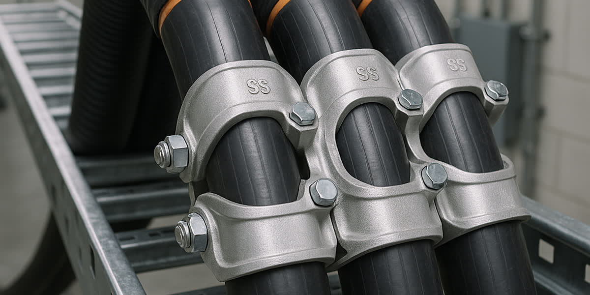
Approved Cleat Materials for Single-Core Applications: - Austenitic Stainless Steel (AISI 316L / 304): Non-magnetic, exceptional tensile strength ($>550\text{ MPa}$), superior corrosion resistance for marine and chemical plants. - Cast Aluminum Alloy (LM6 / A360): Non-magnetic, lightweight, high mechanical rigidity, cost-effective for indoor and substation switchrooms. - High-Impact Engineering Polymers (Glass-Reinforced Polyamide / PA66): Non-magnetic, 100% corrosion-free, dielectric insulation, low smoke zero halogen (LSZH) compliant.
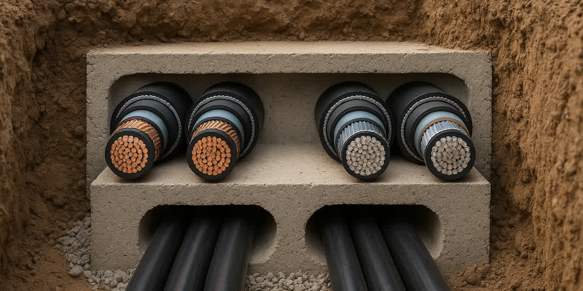
For complex industrial routing spanning containment risers and underground cable systems, non-magnetic structural hardware prevents thermal sheath failure while maintaining maximum containment integrity.
4. IEC 61914:2021 Standard Requirements & Testing Protocols
A cable cleat is defined by IEC 61914 as a dedicated device designed to secure cables when arranged at intervals along the length of the cables, providing retention and resistance to electromechanical forces.
       IEC 61914 TYPE-TEST RIGOR FOR SHORT-CIRCUIT INTEGRITY
┌───────────────────────────────────────────────────────────────────┐
│ 1. Dynamic Peak Current (ip) Injection (3-phase prospective test) │
│ 2. Post-Fault Visual Inspection: Zero release of retained cables  │
│ 3. Post-Fault Electrical Testing: 2.8 kV DC / 1 kV AC Hi-Pot test │
│ 4. Mechanical Retention Verification: No shearing of fixing bolts │
└───────────────────────────────────────────────────────────────────┘
4.1 Short-Circuit Withstand Classification
Under IEC 61914 Clause 6.4, cleats are classified based on short-circuit testing: - Withstand to Short-Circuit (One Short-Circuit): Cleat restrains cable during a single fault; minor permanent deformation permitted provided cables remain secured without sharp edges contacting oversheaths. - Withstand to Short-Circuit (Two Short-Circuits): Cleat withstands an initial short-circuit followed by a second fault without maintenance or re-tightening, proving structural fatigue resistance.
4.2 Environmental & Operational Classifications
- Temperature Rating: Minimum $-40^\circ\text{C}$ / Maximum $+120^\circ\text{C}$.
- Resistance to Corrosion: Class 1 (indoor mild) to Class 4 (offshore marine/high industrial pollutants, AISI 316L).
- Resistance to UV Exposure: Tested per ISO 4892-2 xenon arc exposure for outdoor solar and transmission switchyards.
- Fire & Smoke Toxicity: Low Smoke Zero Halogen (LSZH) self-extinguishing polymer liners meeting UL 94 V-0 and IEC 60695-11-10.
4.3 Elastomeric Cushioning Liners
Direct metal-to-cable contact under heavy mechanical clamping causes point-load notch stress, localized jacket creep, and moisture ingress over years of cyclic thermal expansion. High-grade cleat systems from our engineered fittings and hardware catalog integrate integral low-smoke zero-halogen (LSZH) polymeric or EPDM cushioning pads. These liners absorb dynamic shock loads, accommodate cable radial thermal breathing (+2% to +4% diameter fluctuation between $20^\circ\text{C}$ and $90^\circ\text{C}$ conductor operating temperatures), and prevent outer sheath abrasion.
5. Step-by-Step Engineering Sizing & Spacing Calculation
To ensure complete mechanical compliance, structural engineers must follow a rigorous 5-step sizing protocol.
[ Step 1: Gather Electrical Parameters ] ──► (Ik'', X/R ratio, System Voltage)
                     │
                     ▼
[ Step 2: Determine Peak Current ip    ] ──► (Calculate kappa and dynamic peak)
                     │
                     ▼
[ Step 3: Determine Cable Geometry     ] ──► (Overall Diameter Do, Trefoil S = Do)
                     │
                     ▼
[ Step 4: Calculate Dynamic Force Ft   ] ──► (Ft = 0.17 * ip² / S in N/m)
                     │
                     ▼
[ Step 5: Calculate Cleat Spacing L    ] ──► (L = F_cleat / Ft <= Max Permissible)
5.1 Case Study: 33 kV Wind Farm Substation Step-Up Feeder
An engineering team is designing a 33 kV single-core feeder connecting step-up transformers to GIS switchgear.
Project Data: - Cable Specification: Single-core $1 \times 630\text{ mm}^2$ Copper Conductor, XLPE Insulated, Copper Wire Screened, High-Density Polyethylene Outer Sheath ($33\text{ kV}$ rating per IEC 60502-2). - Cable Overall Diameter ($D_o$): $54.0\text{ mm} = 0.054\text{ m}$. - Arrangement: Trefoil touching formation ($S = 0.054\text{ m}$). - Initial Symmetrical Short-Circuit Current ($I_k''$): $31.5\text{ kA RMS}$. - Substation System $X/R$ Ratio: $14.0$. - Selected Cleat: Heavy-Duty Cast Aluminum Trefoil Cleat with LSZH Cushion Liner, type-tested to IEC 61914 with certified mechanical tensile rating $F_{\text{cleat}} = 18.5\text{ kN} = 18,500\text{ N}$.
Step 1: Calculate Peak Factor ($\kappa$)
$$\kappa = 1.02 + 0.98 \cdot e^{-3 / 14.0} = 1.02 + 0.98 \cdot e^{-0.2143} = 1.02 + (0.98 \cdot 0.8071) = 1.811$$
Step 2: Calculate Dynamic Peak Short-Circuit Current ($i_p$)
$$i_p = \kappa \cdot \sqrt{2} \cdot I_k'' = 1.811 \cdot 1.4142 \cdot 31.5\text{ kA} = 80.68\text{ kA}$$
Step 3: Calculate Maximum Dynamic Peak Force ($F_t$)
$$F_t = \frac{0.17 \cdot i_p^2}{S} = \frac{0.17 \cdot (80.68)^2}{0.054} = \frac{0.17 \cdot 6509.26}{0.054} = \frac{1106.57}{0.054} = 20,492\text{ N/m} = 20.49\text{ kN/m}$$
Step 4: Calculate Maximum Allowable Cleat Spacing ($L$)
$$L_{\text{max}} = \frac{F_{\text{cleat}}}{F_t} = \frac{18,500\text{ N}}{20,492\text{ N/m}} = 0.902\text{ m}$$
Step 5: Engineering Specification & Safety Margin
Rounding down to align with standard cable ladder rung spacing ($300\text{ mm}$ intervals), structural cleats are specified at $600\text{ mm}$ intervals ($0.60\text{ m}$).
At $L = 0.60\text{ m}$, the force experienced by each cleat is: $$F_{\text{actual}} = F_t \cdot L = 20,492\text{ N/m} \cdot 0.60\text{ m} = 12,295\text{ N} = 12.30\text{ kN}$$
Effective Safety Factor: $$\text{SF} = \frac{18.50\text{ kN}}{12.30\text{ kN}} = 1.50 \quad (\text{Exceeds mandatory design criteria})$$
6. Engineered Spacing Reference Tables
To accelerate design reviews, the following engineering lookup table details peak short-circuit forces and recommended cleat center-to-center spacing for standard medium-voltage single-core copper cables across prospective fault levels.
Table: Dynamic Peak Forces ($F_t$) and Cleat Intervals for Single-Core Cu XLPE Cables in Trefoil Formation ($X/R = 14, \kappa = 1.81, F_{\text{cleat}} = 15\text{ kN}$ rating)
| Conductor Size ($\text{mm}^2$) | Nominal Cable OD ($D_o, \text{mm}$) | Fault Level: 25 kA RMS ($i_p = 64.0\text{ kA}$) Force / Spacing | Fault Level: 31.5 kA RMS ($i_p = 80.7\text{ kA}$) Force / Spacing | Fault Level: 40 kA RMS ($i_p = 102.5\text{ kA}$) Force / Spacing | Fault Level: 50 kA RMS ($i_p = 128.1\text{ kA}$) Force / Spacing |
|---|---|---|---|---|---|
| $1 \times 95$ | $32.0$ | $21.78\text{ kN/m}$ / $600\text{ mm}$ | $34.58\text{ kN/m}$ / $400\text{ mm}$ | $55.82\text{ kN/m}$ / $250\text{ mm}$ | $87.17\text{ kN/m}$ / $150\text{ mm}$* |
| $1 \times 150$ | $36.0$ | $19.36\text{ kN/m}$ / $750\text{ mm}$ | $30.74\text{ kN/m}$ / $450\text{ mm}$ | $49.62\text{ kN/m}$ / $300\text{ mm}$ | $77.48\text{ kN/m}$ / $180\text{ mm}$ |
| $1 \times 240$ | $41.0$ | $17.00\text{ kN/m}$ / $850\text{ mm}$ | $26.99\text{ kN/m}$ / $550\text{ mm}$ | $43.57\text{ kN/m}$ / $300\text{ mm}$ | $68.04\text{ kN/m}$ / $200\text{ mm}$ |
| $1 \times 400$ | $47.0$ | $14.83\text{ kN/m}$ / $1000\text{ mm}$ | $23.54\text{ kN/m}$ / $600\text{ mm}$ | $38.01\text{ kN/m}$ / $350\text{ mm}$ | $59.35\text{ kN/m}$ / $250\text{ mm}$ |
| $1 \times 630$ | $54.0$ | $12.91\text{ kN/m}$ / $1100\text{ mm}$ | $20.49\text{ kN/m}$ / $700\text{ mm}$ | $33.08\text{ kN/m}$ / $450\text{ mm}$ | $51.66\text{ kN/m}$ / $280\text{ mm}$ |
*Note: Where calculated spacing falls below ladder rung pitch, utilize intermediate stainless steel restraint straps positioned between structural cleats.
                 INTERMEDIATE STRAP RESTRAINT STRATEGY
   Structural Cleat     Intermediate Strap     Intermediate Strap     Structural Cleat
   (Anchored to Rung)   (Encircles Trefoil)   (Encircles Trefoil)   (Anchored to Rung)
         [====]               (----)                 (----)               [====]
    ───────█────────────────────│──────────────────────│────────────────────█───────
    ═══════╧════════════════════╧══════════════════════╧════════════════════╧═══════
       Cable Ladder        Ladder Rung            Ladder Rung          Cable Ladder
7. Installation Best Practices & Field Failure Prevention
Proper engineering calculations can be undermined by poor installation practices. Site contractors must execute cleating according to strict guidelines:
7.1 Managing Thermal Expansion ("Snaking" Technique)
Cables expand and contract longitudinally under varying electrical load cycles. On continuous horizontal ladder runs exceeding 30 meters, rigidly clamping cables at every point causes excessive compressive axial stress, resulting in severe lateral buckling and sheath rupture. - Snaked Laying: Install cables with a deliberate horizontal sinusoidal wave (sag of approximately 1% to 2% of span length). - Cleating Sequence: Alternate between Fixed Cleats (firmly clamped to ladder rungs with torque wrench) and Guide / Sliding Cleats (retaining the trefoil geometry while allowing longitudinal axial sliding).
          SNAKED CABLE INSTALLATION FOR THERMAL EXPANSION
    Fixed Cleat          Guide Cleat          Fixed Cleat          Guide Cleat
       [ X ]                [ = ]                [ X ]                [ = ]
   ─────█─────────────────────│────────────────────█─────────────────────│─────
      .-'   '-.             .-'   '-.            .-'   '-.             .-'
    -'         '-.       .-'         '-.      .-'         '-.       .-'
                  '-...-'               '-..-'               '-...-'
   ◄────────────── L ──────────────►
7.2 Vertical Risers & Drop Shafts
In vertical riser shafts, gravity loads combine with potential short-circuit forces: 1. Cleats must provide adequate frictional grip without crushing cable insulation (clamping pressure must exceed total suspended cable weight per pitch). 2. Install structural cleats at maximum $1.0\text{ m}$ to $1.2\text{ m}$ vertical intervals. 3. At the top of vertical drops, install heavy-duty quadrant support saddles to prevent acute bending radius violations.
7.3 Securing Bends, Elbows & Switchgear Terminations
Electromagnetic forces exert maximum radial thrust at directional changes and cable bends: - Place structural cleats immediately before and after every bend (within $150\text{ mm}$ of the tangent point). - Within the radius of bends, reduce cleat pitch to $300\text{ mm}$ maximum. - Within $300\text{ mm}$ of MV terminations, transformer bushings, and GIS cable boxes, secure cables rigidly with non-magnetic cleats to ensure dynamic fault forces do not shear heavy-duty cable lugs off equipment terminal palms.
7.4 Electromagnetic Shielding & Control Cabling Segregation
High short-circuit fault currents in single-core power cables generate transient magnetic fields capable of inducing destructive voltage spikes in adjacent low-voltage wiring. Always isolate power trefoils from sensitive shielded control and instrumentation cabling by maintaining minimum physical clearance ($>300\text{ mm}$) or installing grounded solid metallic barrier dividers inside cable trays.
8. Material Selection Matrix for Cable Cleats
Selecting the appropriate cleat material depends heavily on environmental aggressiveness, fire codes, mechanical rating, and budget constraints.
| Material | Tensile Yield Strength | Operating Temp Range | Corrosion Resistance | Flame Retardancy | Recommended Project Applications |
|---|---|---|---|---|---|
| Stainless Steel 316L | Extreme ($>550\text{ MPa}$) | $-60^\circ\text{C}$ to $+150^\circ\text{C}$ | Outstanding (Class 4 Marine / Offshore) | Non-combustible | Offshore oil & gas platforms, coastal substations, chemical processing, nuclear power |
| Cast Aluminum Alloy (LM6) | Very High ($>220\text{ MPa}$) | $-40^\circ\text{C}$ to $+120^\circ\text{C}$ | High (Indoor & Non-saline Outdoor) | Non-combustible | Utility substations, commercial riser shafts, industrial manufacturing switchrooms |
| Glass-Filled Polyamide (PA66) | High ($>110\text{ MPa}$) | $-40^\circ\text{C}$ to $+105^\circ\text{C}$ | Impervious (Zero galvanic or chemical rust) | UL 94 V-0 (LSZH) | Water treatment plants, underground tunnels, transit rail stations, commercial facilities |
| 316 SS Quad / Matrix Straps | Ultra High ($>800\text{ MPa}$) | $-60^\circ\text{C}$ to $+150^\circ\text{C}$ | Outstanding (Marine Grade) | Non-combustible | High-voltage multi-tier bundle containment, extreme fault levels ($>63\text{ kA}$) |
9. Frequently Asked Questions (FAQ)
Q1: Why are standard nylon cable ties or unrated metal straps prohibited for securing single-core power cables?
Standard plastic cable ties and unrated perforated metal bands possess negligible dynamic impact resistance. During a short-circuit fault, peak electromagnetic repulsive forces surge to tens of thousands of Newtons in milliseconds. Plastic ties suffer instant tensile shear fracture, while unrated metal straps deform or saw into the outer jacket. Only cable cleats type-tested and certified to IEC 61914 can guarantee structural containment under dynamic fault loads.
Q2: Why must magnetic steel never be used to construct cleats for single-core AC cables?
A single-core cable carrying alternating current produces an alternating magnetic flux. If surrounded by a closed ferromagnetic steel loop, the loop acts as a shorted transformer core, generating severe eddy currents and magnetic hysteresis losses. This induces rapid localized heating (often exceeding $130^\circ\text{C}$), melting cable jackets and degrading insulation. Only non-magnetic materials (316L stainless steel, cast aluminum, or engineering polymers) are permitted.
Q3: How do intermediate restraint straps differ from structural cable cleats?
A structural cable cleat is mechanically bolted directly to the cable ladder rung or support channel, providing both geometric cable retention and structural anchoring to the building steelwork. An intermediate restraint strap encircles the three cables in trefoil formation without being fastened to the ladder. It binds the cables together against mutual repulsive forces, reducing the required number of structural cleats while lowering installation costs and structural ladder load.
Q4: What is the difference between peak fault current ($i_p$) and symmetrical fault current ($I_k''$) in cleat calculations?
Symmetrical fault current ($I_k''$) is the steady-state RMS AC component of the fault. The peak fault current ($i_p$) includes the maximum asymmetrical DC offset occurring in the first half-cycle (3 ms to 5 ms) following fault initiation. Because electromechanical forces scale with the square of the instantaneous current ($i_p^2$), using $I_k''$ instead of $i_p$ underestimates dynamic forces by a factor of 4 to 8, leading to undersized cleats and catastrophic containment failure.
Q5: How does ambient temperature affect cable cleat selection?
In extreme environments (such as desert solar farms reaching $+50^\circ\text{C}$ ambient or arctic installations below $-30^\circ\text{C}$), polymer cleats can suffer UV embrittlement, thermal creep, or cold-temperature shattering under dynamic impact. For high-temperature, outdoor, or hazardous environments, 316L stainless steel or LM6 cast aluminum cleats with UV-stabilized LSZH cushioning liners provide the highest reliability and longest operational lifespan.
10. Summary & Engineered Project Support
Cable cleating is a mission-critical safety system safeguarding life, property, and power grid reliability. Designing single-core cable containment demands rigorous mathematical analysis: 1. Accurately calculate dynamic peak current $i_p$ using prospective symmetrical fault levels ($I_k''$) and system $X/R$ ratios per IEC 60909-0. 2. Apply IEC 61914 electromechanical force equations based on installation geometry (Trefoil vs. Flat). 3. Insist strictly on non-magnetic materials (316L Stainless Steel, Cast Aluminum, or Engineered Polymers) with elastomeric LSZH cushioning liners. 4. Calculate maximum cleat spacing with verified safety margins, integrating intermediate restraint straps for high fault currents ($>40\text{ kA}$). 5. Implement thermal snaking, bend anchoring, and vertical riser support protocols during installation.
Zhengzhou Sitong Cable Co., Ltd. (SiTong Cable) is a premier global manufacturer of medium and low voltage power cables, bare overhead conductors, and engineered cable systems certified to IEC, BS, ASTM, and AS/NZS standards. Our dedicated technical engineering department provides comprehensive fault level calculations, cable sizing optimization, and complete turnkey accessory solutions for utility, industrial, and renewable EPC projects worldwide.
Further Engineering Resources & Inquiries
👉 Browse our Medium & Low Voltage Power Cable Range 👉 Medium & High Voltage Power Cable Sheath Bonding & Earthing Guide 👉 Contact Zhengzhou Sitong Cable Technical Team
📬 Sales & Engineering Inquiries: sales@sitongcable.com | 📞 Phone: +86-371-69176007