Steel Tape Armour (STA) vs Steel Wire Armour (SWA) vs Aluminium Wire Armour (AWA): Mechanical Protection, Non-Magnetic Physics and Earthing Engineering Guide
Steel Tape Armour (STA) vs Steel Wire Armour (SWA) vs Aluminium Wire Armour (AWA): Mechanical Protection, Non-Magnetic Physics and Earthing Engineering Guide
Comprehensive engineering comparison of STA, SWA, and AWA for low and medium voltage power cables: mechanical impact resistance, tensile pulling strength, single-core magnetic eddy-current heating mitigation, and adiabatic earthing calculation per IEC 60502 and BS 5467.
Armoured power cables serve as the primary lifeline for electrical energy distribution across hazardous, underground, and mechanically demanding industrial environments. When engineers, EPC contractors, and procurement managers select cables for harsh operating conditions—such as direct burial in rocky trenches, vertical mine shafts, offshore substations, or chemical manufacturing plants—the choice of the metallic armour layer represents a pivotal design decision. Selecting between Steel Tape Armour (STA), Steel Wire Armour (SWA), and Aluminium Wire Armour (AWA) determines not only the mechanical survival of the installation against crushing loads and longitudinal tensile forces, but also dictates the electromagnetic thermal stability, fault current return capability, and lifecycle cost of the power asset.
Despite their widespread use under international standards such as IEC 60502-1, IEC 60502-2, BS 5467, BS 6724, and DIN VDE 0276-603, dangerous misapplications frequently occur in field engineering. The most catastrophic error involves specifying ferromagnetic steel armour (SWA or STA) on single-core alternating current (AC) cables, leading to severe magnetic hysteresis overheating, insulation melting, and uncontained cable failure. Furthermore, improper sizing of the metallic armour layer can compromise the system's Circuit Protective Conductor (CPC) performance during a phase-to-earth short-circuit fault.
This comprehensive technical guide delivers an exhaustive engineering analysis of STA, SWA, and AWA cable constructions. We evaluate their structural differences, mechanical crush and tensile resistance profiles, electromagnetic induction physics in single-core vs multi-core systems, adiabatic earthing calculations per BS 7671 and IEC 60364-5-54, and optimal specification criteria across utility, mining, and infrastructure projects.
1. Fundamental Anatomy and Primary Functions of Cable Armour
To understand armour selection, electrical engineers must first distinguish between metallic screening/shielding and metallic armouring. While metallic screens (composed of copper tape, concentric copper wires, or lead sheaths) are designed primarily for radial electric field distribution, capacitive charging current drain, and electromagnetic compatibility (EMC), the armour layer is engineered primarily for mechanical defense against external aggression.
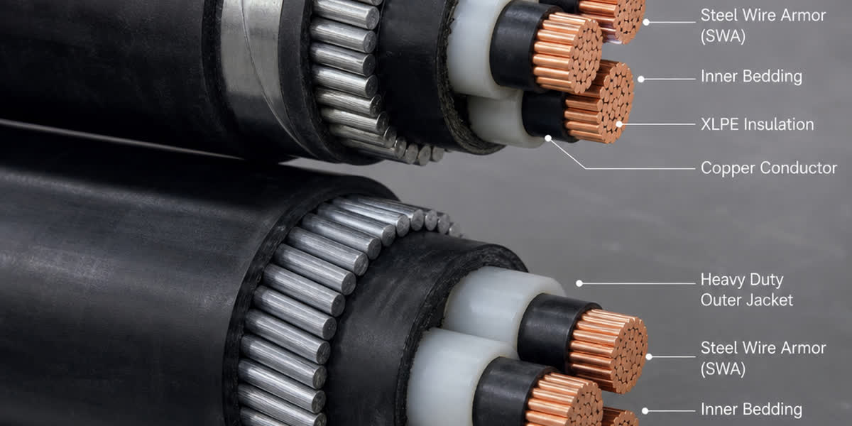
In accordance with IEC 60502-1 (for low-voltage cables up to 0.6/1 kV) and IEC 60502-2 (for medium-voltage cables from 6 kV up to 36 kV), a typical armoured cable incorporates the following concentric layers from the inside out: 1. Phase Conductors: Class 2 stranded compact copper (Cu) or aluminium (Al) conductors. 2. Conductor Screen and Insulation: Extruded semi-conducting screen, Cross-Linked Polyethylene (XLPE) or Tree-Retardant XLPE (TR-XLPE) rated for 90°C continuous operation and 250°C short-circuit thermal limit. 3. Insulation Screen and Metallic Screen: Semi-conducting layer followed by helically applied copper tape or copper wire screen (mandatory on MV cables; optional on LV). 4. Assembly / Inner Bedding (Sheath): Extruded PVC, LSZH, or Polyethylene (PE) layer providing a smooth, uniform cylindrical foundation that cushions the insulated cores and prevents the metallic armour from biting into the insulation during bending or thermal cycling. 5. Metallic Armour Layer: Helically applied double steel tapes (STA), a single layer of galvanized steel wires (SWA), or aluminium wires (AWA). 6. Non-Metallic Outer Sheath (Oversheath): Extruded thermoplastic PVC (Type ST2), Medium-Density Polyethylene (MDPE Type ST7), or Low-Smoke Zero-Halogen (LSZH Type ST8) compound providing environmental, moisture, and chemical isolation.
For critical infrastructure and utility feeders, our underground cable range incorporates precision-engineered bedding and armouring geometries designed to withstand high radial soil pressure and ground shifting without micro-deforming the underlying primary insulation.
2. Technical Construction Comparison: STA vs SWA vs AWA
The fundamental divergence among STA, SWA, and AWA stems from the geometry of the metallic elements, their material metallurgy, and the resulting mechanical resistance characteristics.
Double Steel Tape Armour (STA / DSTA)
Steel tape armour consists of two layers of low-carbon galvanized mild steel tape wound helically over the inner bedding in the same direction. According to IEC 60502-1, the outer tape is applied so that it covers the helical gap left by the inner tape with an overlap of at least 33% (frequently engineered to 50% overlap). - Mechanical Strength Profile: Exceptional radial compressive strength and crush resistance. It effectively deflects direct compressive loads from heavy backfill, roadway traffic, and sharp digging tools (such as spades or pickaxes). - Tensile Strength Profile: Extremely low longitudinal tensile capacity. Under pulling tension, helical steel tapes tend to unwind, slide, or shear, offering negligible support for cable pulling or vertical suspension. - Flexibility: Moderate radial flexibility, but prone to tape displacement or deformation when bent below its minimum bending radius (typically 12 x D to 15 x D).
Galvanized Steel Wire Armour (SWA)
Steel wire armour consists of a single layer of cylindrical galvanized steel wires applied helically with a long lay length around the bedding, ensuring a nominal coverage of at least 90% to 95%. The wire diameter is standardized based on the cable diameter under the armour, typically ranging from 0.9 mm to 3.15 mm per BS 5467 and IEC 60502-1. - Mechanical Strength Profile: High localized impact resistance against point loads (e.g., jagged rocks in backfill). - Tensile Strength Profile: Outstanding longitudinal tensile pulling capability. SWA can bear significant mechanical tension, making it ideal for pulling through long ducts, hanging down vertical shafts, pulling across river crossings, or laying on steep gradients. - Flexibility: Stiff along the axial direction, requiring larger bending radii (12 x D to 15 x D for multi-core cables) and robust pulling equipment.
Aluminium Wire Armour (AWA)
Aluminium wire armour shares the identical physical geometry with SWA—a single layer of round wires wound helically—but utilizes electrical-grade non-magnetic aluminium alloy wires (typically 1000 or 5000 series aluminium with tensile strength of 120–160 MPa) instead of galvanized steel. - Mechanical Strength Profile: Adequate radial protection and moderate tensile capacity. While aluminium has lower tensile strength and hardness than carbon steel, it provides sufficient defense against backfill stones and pulling tension in single-core runs. - Electromagnetic Profile: Completely non-magnetic (relative permeability approx. 1.0), eliminating magnetic hysteresis and minimizing eddy-current losses in alternating current fields.
Comprehensive Engineering Comparison Matrix
| Technical Parameter | Double Steel Tape Armour (STA) | Galvanized Steel Wire Armour (SWA) | Aluminium Wire Armour (AWA) |
|---|---|---|---|
| Relevant Standards | IEC 60502-1, IEC 60502-2, DIN VDE 0276-603 | BS 5467, BS 6724, IEC 60502-1/2, BS 7835 | BS 5467, BS 6724, IEC 60502-1/2 |
| Armour Material | Galvanized Mild Steel Tape (Double Layer) | Galvanized High-Tensile Steel Wire | High-Conductivity Aluminium Alloy Wire |
| Magnetic Permeability (mu_r) | High Ferromagnetic (mu_r approx. 300 - 1000) | High Ferromagnetic (mu_r approx. 300 - 1000) | Non-Magnetic (mu_r = 1.0) |
| Tensile Load Capacity | Negligible (< 10 N/mm2 allowable pull) | Superior (up to 400–600 N/mm2 wire rating) | Moderate (approx. 120–160 N/mm2 wire rating) |
| Radial Crush Resistance | Superior (Uniform surface plate shielding) | High (Point-contact load distribution) | Moderate (Ductile deformation under severe point impact) |
| Rodent and Termite Defense | Maximum (Impenetrable continuous metallic barrier) | Excellent (Interstices require tight oversheath) | Very Good |
| Applicable Cable Construction | Multi-Core Cables ONLY (3-core, 4-core, 5-core) | Multi-Core Cables ONLY (AC systems) | Single-Core Cables ONLY (AC systems) |
| Electrical Conductivity | Low (approx. 10% - 14% IACS) | Moderate (approx. 10% - 15% IACS) | High (approx. 50% - 61% IACS) |
| Direct Burial Suitability | Outstanding (Stable trenches, road crossings) | Outstanding (Rocky, unstable ground, shifting soil) | Excellent (Protected single-core trenches) |
| Vertical Shaft / Borehole Use | Unsuitable (Risk of tape elongation and rupture) | Premier choice (Bears total suspended self-weight) | Good for single-core vertical risers |
| Relative Weight Impact | Moderate (+15% to +25% total weight) | High (+25% to +45% total weight) | Low (+10% to +18% total weight) |
Within our comprehensive power cable portfolio, every armoured variant is manufactured with strict compliance to nominal armour thickness tolerances to prevent premature fatigue under cyclic operational vibration.
3. Electromagnetic Physics: Why Steel Armour Destroys Single-Core AC Cables
The single most critical theoretical principle governing armoured cable engineering is Ampere's Circuital Law and Faraday's Law of Electromagnetic Induction.
The Phenomenon in Multi-Core Cables
In a three-phase cable containing three phase cores (L1, L2, L3) enclosed within a common outer armour, the instantaneous vector sum of the balanced load currents is zero:
I_L1(t) + I_L2(t) + I_L3(t) approx 0
Because the net enclosed current through the cross-section bounded by the armour perimeter is negligible, virtually zero net alternating magnetic flux penetrates the enclosing steel tape or steel wire layer. Consequently, magnetic losses are minimal, and magnetic steel armour (STA or SWA) can be utilized on multi-core cables without excessive heating.
The Catastrophic Failure Mode in Single-Core Cables
When a single-core cable carries alternating current (I_phase), the single conductor generates a continuous, concentrated alternating magnetic field concentric with the cable axis. If this single core is surrounded by a ferromagnetic steel armour (such as SWA or STA), the ferromagnetic material provides a low-reluctance magnetic path (mu_r >> 1). This creates two catastrophic electromagnetic effects:
- Magnetic Hysteresis Losses: The alternating magnetic field forces the magnetic domains within the ferromagnetic steel to repeatedly reverse polarity at 50 Hz or 60 Hz. The energy lost per cycle is proportional to the area of the hysteresis loop (Steinmetz relationship). In carbon steel, this produces intense, continuous volumetric heat.
- Eddy Current Losses: The changing magnetic flux induces high circulating eddy currents within the conductive steel, generating resistance heating proportional to the square of frequency, magnetic flux density, and wire/tape thickness.
These combined magnetic losses act as an auxiliary heat source directly surrounding the insulation bedding. In field installations where single-core SWA cables were mistakenly installed on AC feeders, thermal imaging revealed armour temperatures surpassing 130°C within hours of loading—even when the copper core was operating well below its rated ampacity! This intense external heating rapidly drives the XLPE insulation past its 90°C thermal degradation threshold, resulting in thermal runaway, severe dielectric breakdown, and phase-to-earth faults.
The Engineering Solution: Aluminium Wire Armour (AWA)
To eliminate magnetic hysteresis and drastically suppress eddy currents, international standards (such as BS 5467, BS 6724, and IEC 60502-1) mandate that single-core AC armoured cables must utilize non-magnetic armour.
Because aluminium has a relative magnetic permeability of unity (mu_r approx. 1.0), it behaves magnetically like free space. No magnetic flux concentrates within the armour layer, entirely preventing hysteresis losses. While eddy currents can theoretically circulate due to aluminium's high electrical conductivity, the round wire geometry and long helical lay prevent closed transverse loops, keeping electromagnetic losses negligible.
In direct current (DC) circuits (such as HVDC or DC traction power), magnetic induction does not alternate, meaning steel armour could theoretically be utilized. However, standardizing on AWA or stainless steel tape for single-core cables remains standard industry best practice to prevent miswiring errors during substation retrofits.
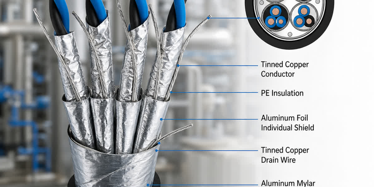
For multi-conductor signal, telemetry, and automated process wiring where shielding against low-frequency electromagnetic interference is paramount, engineers should consult our industrial control cable lineup, which integrates high-coverage copper braiding with steel tape armouring for combined EMI shielding and crush protection.
4. Mechanical Load Engineering: Pulling Tension, Crushing and Environmental Selection
In field deployments, cables encounter diverse static and dynamic mechanical stresses during installation and decades of operation.
Maximum Permissible Pulling Tension Calculation
During trench or duct installation, pulling force can be applied either to the central phase conductors using a pulling eye, or directly to the armour layer using a cable stocking (cable grip).
When pulling multi-core SWA cables via cable stocking over the armour, the galvanized steel wires absorb substantial tensile load. The allowable pulling tension is calculated using:
T_armour = sigma_allowable * A_wire
where: - sigma_allowable is the maximum permissible tensile stress for galvanized steel wire (typically taken as 100 N/mm2 to avoid permanent plastic strain of the oversheath bedding). - A_wire is the total aggregate cross-sectional area of all steel wires in the armour layer: A_wire = N * (pi * d_w^2 / 4) with N being the number of wires and d_w the individual wire diameter.
Conversely, for STA (Steel Tape Armoured) cables, pulling force must NEVER be applied to the armour layer. The helical tape configuration possesses zero longitudinal elongation restraint; pulling on the tape causes it to bite through the bedding into the core insulation or break the tape overlap, stripping the outer jacket. All pulling tension for STA cables must be transmitted exclusively through the conductor cores using pulling eyes soldered or crimped to the conductors: - Copper conductors: T_conductor = 50 N/mm2 * A_total_Cu - Aluminium conductors: T_conductor = 30 N/mm2 * A_total_Al
Vertical Shafts, Risers, and Mine Shaft Suspensions
For vertical installations—such as high-rise building electrical risers, hydro plant penstocks, and underground mine shafts—the cable must support its entire suspended self-weight over the vertical drop without stretching the internal conductors. - SWA cables are universally required for vertical drops exceeding 15 meters. The interlocking helical wire cage forms a rigid self-supporting column when properly clamped at the top with specialized cone-gland suspension clamps. - STA cables will experience tape slippage, jacket necking, and core insulation elongation under vertical gravity loads, making STA strictly prohibited for unsupported vertical risers.
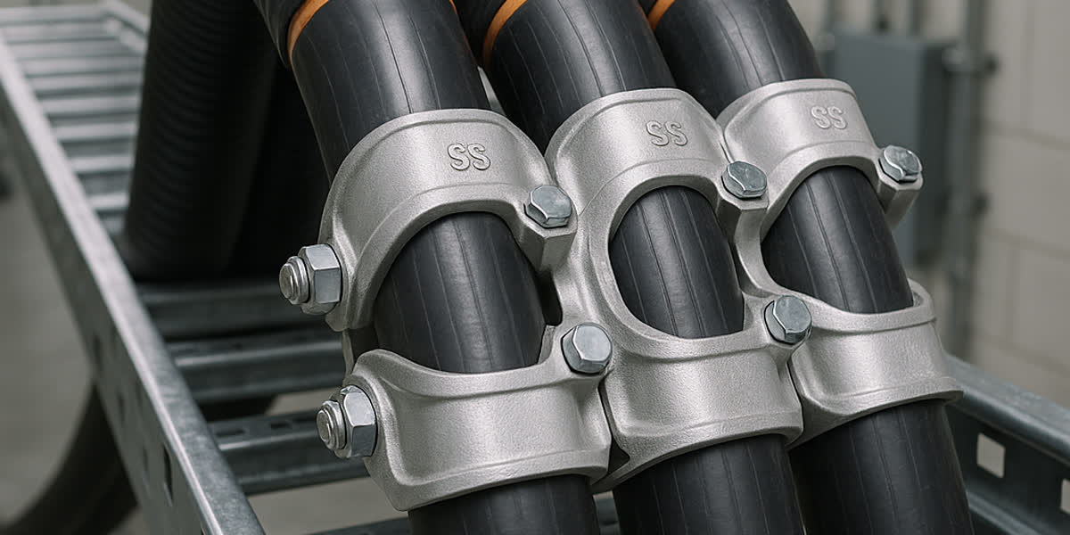
To safely anchor vertical runs and prevent structural displacement under mechanical vibrations or short-circuit magnetic repulsion, engineers must install heavy-duty cable cleats and fittings spaced according to IEC 61914 standards.
5. Electrical Earthing, Circuit Protective Conductor (CPC) Function and Adiabatic Sizing
In low-voltage and medium-voltage electrical installations, an armoured cable's metallic layer frequently serves a dual role: physical protection and an electrical earth fault return path (Circuit Protective Conductor / CPC).
Can SWA or AWA Serve as the Sole CPC?
Under BS 7671 (IET Wiring Regulations, Regulation 543.1) and IEC 60364-5-54, the metallic armour of an SWA or AWA cable may be utilized as the sole circuit protective conductor if, and only if, its effective cross-sectional area satisfies the adiabatic equation:
S >= sqrt(I_f^2 * t) / k
where: - S is the minimum required cross-sectional area of the armour (mm2). - I_f is the prospective symmetrical earth fault current (r.m.s. Amperes). - t is the operating time of the protective disconnection device (seconds), typically <= 0.2 s to 5.0 s. - k is the material factor reflecting the thermal resistivity, specific heat capacity, and initial/final temperature limits of the armour metal per BS 7671 Table 54.4: - Galvanized Steel Wire (SWA) with 70°C initial temperature (PVC sheath) and 200°C final temperature: k approx. 51 - Galvanized Steel Wire (SWA) with 90°C initial temperature (XLPE/LSZH sheath) and 200°C final temperature: k approx. 46 - Aluminium Wire (AWA) with 90°C initial temperature and 200°C final limit: k approx. 85 - 93 - Copper Conductor (for reference): k = 143
Practical Engineering Pitfall: Large Cross-Section SWA Cables
A common engineering pitfall occurs with multi-core cables of large conductor sizes (e.g., 4C x 185 mm2 or 4C x 240 mm2): - In smaller cable sizes (e.g., up to 4C x 16 mm2), the circumference dictates a high quantity of steel wires relative to the conductor cross-section, easily satisfying S >= sqrt(I^2 * t) / k. - In large conductor cables, the cross-sectional area of the copper phase conductors increases with the square of the radius, while the armour cross-sectional area increases only linearly with the cable perimeter. - Because the electrical conductivity of steel is only roughly 10% to 12% that of copper (k_steel = 46 vs k_copper = 143), the effective thermal fault capacity of the steel wire layer may fall short of matching the required phase conductor protection ratio!
If the prospective fault current clearing time is prolonged (e.g., upstream breaker trip delay of 1.0 s), the SWA alone may overheat and melt the outer PVC/LSZH jacket during a short-circuit fault. In such installations, engineers must specify a supplementary internal or external copper earth continuity conductor (ECC) run in parallel with the cable.
Conversely, Aluminium Wire Armour (AWA) exhibits significantly higher electrical conductivity (approx. 55% IACS) and a higher k-factor (k = 85), providing superior fault current carrying capacity per unit area compared to steel.
To guarantee low-impedance electrical continuity and prevent arc sparking during high-magnitude earth faults, cable terminations must be completed using certified, corrosion-resistant cable lugs and bimetallic terminations coupled with brass CW-type or E1W-type industrial glands featuring integral earth tags.
6. Bedding and Oversheath Materials for Corrosive and Extreme Environments
The mechanical integrity of the armour is critically reliant on the chemical protection provided by the non-metallic inner bedding and outer oversheath. If moisture or acidic soil chemicals breach the oversheath, the underlying galvanized steel wires will undergo rapid galvanic corrosion, leading to mechanical collapse and loss of earthing continuity.
Oversheath Compound Engineering
- PVC (Polyvinyl Chloride - ST2):
- Advantages: Cost-effective, flame-retardant (IEC 60332-1), excellent resistance to water, oils, and weak acids.
- Limitations: Contains halogens, generating dense, toxic, corrosive hydrogen chloride (HCl) gas in fires; stiffens and cracks at temperatures below -5°C.
- MDPE / HDPE (Medium/High-Density Polyethylene - ST7):
- Advantages: Exceptional water impermeability, superior abrasion resistance, high tensile toughness against rocky backfills, outstanding environmental stress crack resistance (ESCR). Ideal for long-term direct burial in marshlands or coastal waterlogged soils.
- Limitations: Flammable (propagates flame without additives); rigid handling during cold-weather pulls.
- LSZH / LSHF (Low-Smoke Zero-Halogen - ST8):
- Advantages: Mandatory for tunnels, metro systems, underground substations, commercial high-rises, and offshore platforms. Emits zero halogen acids and minimal non-toxic smoke under fire conditions (IEC 60754-1/2, IEC 61034-2).
- Limitations: Higher material cost; slightly lower tear and puncture resistance compared to HDPE, necessitating robust SWA or STA beneath the sheath.
7. SiTong Cable Manufacturing Precision and Quality Verification
At SiTong Cable (Zhengzhou Sitong Cable Co., Ltd. / 郑州四通电缆有限公司), we operate state-of-the-art heavy planetary cage armouring and high-speed tape wrapping lines capable of applying precision metallic protection up to 132 kV power cable ratings.
In-House Testing and Standards Compliance
Every production batch undergoes rigorous factory acceptance testing (FAT) strictly conforming to IEC 60502, BS 5467, ASTM A475, and AS/NZS 1429.1: 1. Zinc Coating Mass and Uniformity Testing (Preece Test / ASTM A90): Verifying that galvanized steel wires meet Class A or Class B zinc coating weights (>= 200 g/m2) to guarantee 30+ years of subterranean corrosion resistance. 2. Armour Wire Tensile and Elongation Testing: Verifying tensile strength (390 - 540 N/mm2) and minimum 10% elongation to prevent wire snap during high-tension factory cabling. 3. Spark Testing on Oversheath: 100% continuous spark testing up to 15 kV AC/DC on extruded bedding and outer jackets to eliminate pinholes and micro-voids prior to drum packaging. 4. DC Resistance of Armour: Precise Kelvin double-bridge measurement verifying that armour electrical resistance conforms to BS 5467 tables for earth-loop impedance compliance.
Our technical department provides full engineering support, including short-circuit thermal calculation reports, customized drum lengths for minimal jointing, and third-party type test certifications (CE, KEMA, TUV) for international utility tenders.
8. Frequently Asked Questions (FAQ)
Q1: Can I use Steel Wire Armour (SWA) on a single-core 400V or 11kV AC cable?
No, absolutely not. Installing ferromagnetic steel wire armour (SWA) or steel tape armour (STA) on a single-core alternating current (AC) cable creates a closed magnetic circuit around the single phase conductor. The continuous alternating current induces severe magnetic hysteresis and eddy-current losses in the steel, generating extreme heat that will exceed the XLPE insulation's 90°C thermal limit and cause thermal runaway and cable failure. Single-core AC armoured cables must always use non-magnetic Aluminium Wire Armour (AWA) or non-magnetic stainless steel / brass tape.
Q2: What is the primary difference in application between STA and SWA?
The primary difference is tensile pulling strength versus radial crush resistance. Double Steel Tape Armour (STA) provides superior, continuous planar protection against heavy compressive loads, direct burial crushing, and sharp tools (e.g., digging shovels), but has virtually zero longitudinal tensile strength. SWA provides high tensile pulling strength and high point-impact resistance, making it suitable for pulling through steep conduits, hanging in vertical mine shafts/risers, and laying in shifting or rocky ground.
Q3: When can the cable armour be used as the sole Circuit Protective Conductor (CPC)?
The armour can serve as the sole CPC under BS 7671 and IEC 60364-5-54 if its calculated cross-sectional area satisfies the adiabatic equation S >= sqrt(I^2 * t) / k. While small-to-medium multi-core SWA cables (up to 16 - 35 mm2) usually possess sufficient steel wire area to satisfy this rule, large-conductor cables (185 mm2 and above) frequently have insufficient armour cross-section due to the high electrical resistivity of steel. In such cases, a supplementary internal or external copper earth continuity conductor is mandatory.
Q4: Does Aluminium Wire Armour (AWA) corrode faster than Steel Wire Armour (SWA)?
Aluminium naturally forms a protective oxide layer that resists atmospheric corrosion. However, in subterranean environments with acidic soils, alkaline groundwater, or road salts, unprotected aluminium can be susceptible to pitting. For this reason, high-integrity outer sheaths (such as MDPE or high-grade PVC) are extruded over the AWA layer. Furthermore, when terminating AWA cables in outdoor switchgear, bimetallic brass-to-aluminium connection hardware and weatherproof CW/E1W glands must be used to eliminate galvanic corrosion between dissimilar metals.
Q5: What is the recommended minimum bending radius for SWA vs STA cables?
Per IEC 60502 and BS standards: - Multi-core SWA power cables typically require a minimum installation bending radius of 12 x Overall Diameter (OD) for smaller sizes to 15 x OD for large multi-core conductors. - Single-core AWA cables require a bending radius of 15 x OD. - Multi-core STA cables typically require 12 x OD. Never bend an armoured cable below its specified minimum radius, as severe bending can cause steel tapes to displace/overlap abnormally or cause steel wires to birdcage and crush the inner bedding.
9. Engineering Support and Project Procurement
Selecting the appropriate cable armouring architecture safeguards multimillion-dollar industrial and utility infrastructures against unplanned outages, electrical faults, and premature ground degradation. Whether your project requires high-tensile SWA power feeders for vertical mine shafts, crush-resistant STA cables for direct burial under roadway crossings, or non-magnetic AWA single-core transmission lines, SiTong Cable delivers tailored engineering designs and rigorous quality assurance.
👉 Browse our Medium and Low Voltage Power Cable Range
👉 Cable Cleat Selection and Short-Circuit Force Calculation: Engineering Guide to IEC 61914
👉 Contact SiTong Cable Engineering Team for Custom Cable Design
📬 Sales inquiries: sales@sitongcable.com | 📞 Phone: +86-371-69176007