Instalación y Mantenimiento de Cable Concéntrico: Guía Completa de Campo para Redes de Distribución de Baja y Media Tensión
Instalación y Mantenimiento de Cable Concéntrico: Guía Completa de Campo para Redes de Distribución de Baja y Media Tensión
Los cables concéntricos se utilizan ampliamente en redes de distribución subterránea de baja tensión (0,6/1 kV) y media tensión (6,6/11 kV a 19/33 kV) en todo el mundo, valorados por su diseño de neutro integrado que combina el conductor de neutro/tierra y la protección mecánica en una sola capa helicoidal de alambres. Este diseño reduce el ancho de zanja entre un 30–50% y la mano de obra de instalación hasta un 40% en comparación con los sistemas de cables múltiples agrupados. Sin embargo, la construcción única del neutro concéntrico también introduce desafíos distintos de instalación y mantenimiento, desde el control adecuado del radio de curvatura hasta la gestión de la corrosión de los alambres neutros.
Esta guía de campo está dirigida a contratistas eléctricos, linieros de servicios públicos, ingenieros de sitio y cuadrillas de mantenimiento que instalan y mantienen cables concéntricos en el campo. Cubre la preparación previa a la instalación, procedimientos de tendido y colocación, técnicas de empalme y terminación, protocolos de inspección y prueba, programas de mantenimiento rutinario y resolución de problemas comunes, todo referenciado a las normas internacionales aplicables.
Preparación Previa a la Instalación
Una preparación adecuada antes de que el cable llegue al sitio previene los defectos de instalación más comunes: daños mecánicos, entrada de humedad y curvatura incorrecta.
Lista de Verificación de Recepción y Almacenamiento
| Elemento de Inspección | Criterio de Aceptación | Acción ante No Conformidad |
|---|---|---|
| Estado del carrete | Sin grietas, bridas rotas ni clavos sobresalientes | Fotografiar y rechazar; solicitar carrete de reemplazo |
| Sellos de extremos del cable | Ambos extremos sellados con tapas no higroscópicas; sin humedad visible | Retirar y resellar con tapas termocontraíbles; registrar para garantía |
| Inspección visual de la cubierta | Sin cortes, abrasiones ni torceduras a lo largo visible | Medir profundidad; si >10% del espesor de cubierta, cortar y reterminar |
| Resistencia del conductor | Resistencia DC ≤ máximo IEC 60228 por sección transversal | Rechazar el lote si algún carrete excede el límite |
| Resistencia de aislamiento (Megger) | BT: ≥100 MΩ/km a 500 V CC; MT: ≥1000 MΩ/km a 2,5 kV CC | Secar o reemplazar; no instalar cable húmedo |
| Continuidad del neutro | Alambres helicoidales continuos, sin hilos rotos | Reparar o reemplazar la sección afectada |
| Dirección de giro del carrete | Marcada con flecha; el cable se paga desde la parte superior | Reorientar el soporte del carrete antes del tendido |
Lista de Verificación de Herramientas y Equipos
| Categoría de Herramienta | Equipo Requerido | Notas de Aplicación |
|---|---|---|
| Tendido | Gripa de tendido (cesta tejida o Kellems), giratorio, cuerda de tendido (polipropileno, factor de seguridad mínimo 2×), lubricante de tendido (base agua, compatible con cubierta PE/PVC) | Nunca tirar por los alambres neutros concéntricos — siempre tirar por el conductor usando una gripa de cesta aplicada sobre la cubierta |
| Curvatura | Rodillos para cable (rectos y de esquina), plantillas de radio de curvatura (mínimo 12× DE para BT, 15× DE para MT) | Preajustar rodillos de esquina al radio requerido antes del tendido |
| Corte | Cortacables de trinquete (hidráulico para ≥240 mm²), sierra de mano con hoja de diente fino (solo para alambres neutros) | Las ruedas abrasivas generan calor que daña el aislamiento XLPE |
| Pelado | Herramienta de pelado de capa semiconductora, pelador de aislamiento (profundidad ajustable), cuchillo para cable | Para MT: usar herramienta de pelado de capa semiconductora para evitar dañar el aislamiento |
| Terminación | Dados de compresión (coincidentes con especificaciones del fabricante de la terminal), llave dinamométrica, pistola de calor (para terminaciones termocontraíbles) | Verificar que el cierre del dado coincida con el ancho del conector según especificación del fabricante |
| Prueba | Megger (5 kV para MT), probador de Hi-Pot CC, TDR (Reflectómetro de Dominio Temporal) | Calibrar anualmente según ISO 17025 |
Condiciones Ambientales
La temperatura ambiente durante el tendido debe ser superior a 0 °C para cables con cubierta de PE y superior a −5 °C para cables con cubierta de PVC. Por debajo de estas temperaturas, la cubierta se vuelve frágil y propensa a agrietarse durante la curvatura. Si la instalación en clima frío es inevitable, precalentar el carrete en un recinto calefaccionado a 15–25 °C durante un mínimo de 24 horas antes del tendido.
⚠️ Advertencia de Clima Frío: Nunca use un soplete o llama directa para calentar un carrete de cable. Use solo calefacción por aire forzado.
Cálculos de Ingeniería para la Instalación
Se deben realizar dos cálculos críticos antes de cualquier tendido de cable concéntrico: la tensión máxima de tendido y el radio mínimo de curvatura.
Tensión Máxima de Tendido
La tensión máxima de tendido para un cable concéntrico está determinada por el conductor y los alambres neutros. La fórmula según IEEE 1185 e ICEA P-54-440 es:
T_max = C × A × n
Donde:
- T_max = tensión máxima de tendido permitida (N)
- C = constante del conductor (cobre: 70 N/mm²; aluminio: 40 N/mm²)
- A = área transversal de un solo conductor (mm²)
- n = número de conductores (típicamente 1 para cable concéntrico unipolar)
Ejemplo: Cable concéntrico unipolar de 95 mm² con conductor de aluminio:
T_max = 40 × 95 × 1 = 3800 N (aproximadamente 387 kgf)
💡 Regla Práctica: Nunca exceda 3800 N (≈387 kgf) para cables concéntricos con conductor de aluminio hasta 95 mm². Para conductores de cobre, el límite aumenta a aproximadamente 6650 N para 95 mm².
Procedimiento de Instalación — Paso a Paso
Paso 1: Preparación de Zanja e Instalación de Ductos
Excave una zanja con ancho mínimo de 300 mm para cables individuales y 450 mm para múltiples cables lado a lado. Profundidad de zanja según IEC 60364-5-52 y NEC Table 300.5:
| Tensión | Profundidad de Enterramiento Directo | Profundidad de Banco de Ductos |
|---|---|---|
| BT (0,6/1 kV) | 600 mm | 450 mm |
| MT (11 kV) | 900 mm | 750 mm |
| MT (33 kV) | 1200 mm | 1000 mm |
Coloque 100 mm de arena cribada o tierra fina (tamaño máximo de partícula 10 mm) como capa de asiento. Instale cinta de advertencia 300 mm por encima del cable.
Paso 2: Posicionamiento del Carrete y Desenrollado
Posicione el carrete de modo que el cable se pague desde la parte superior. Monte el carrete en un gato hidráulico o soporte de eje que permita la rotación libre. Use un sistema de freno para evitar el sobre-giro — el pago descontrolado causa torceduras.
Paso 3: Tendido del Cable
- Coloque la gripa de tendido de cesta tejida sobre la cubierta del cable — nunca solo sobre los alambres neutros.
- Conecte un giratorio entre la gripa de tendido y la cuerda de tracción para evitar torsiones.
- Aplique lubricante de tendido uniformemente a lo largo de toda la longitud de tracción, especialmente en puntos de entrada y curvas.
- Tire a una velocidad constante de 3–6 m/min para BT, 2–4 m/min para MT. La velocidad excesiva genera calor por fricción y puede dañar la cubierta.
- Monitoree la tensión de tendido continuamente. Registre la tensión máxima en cada curva y al final del tendido.
Paso 4: Colocación del Cable con Serpenteo
En instalaciones en zanja, coloque el cable con ligero serpenteo (aproximadamente 2–3% de longitud extra) para acomodar la expansión térmica y el asentamiento del suelo. Para enterramiento directo, el cable debe reposar sobre la capa de asiento en una curva en S suave en lugar de una línea recta.
Paso 5: Empalme y Terminación
Las uniones y terminaciones de cables concéntricos deben preservar la integridad tanto del sistema de aislamiento como de la ruta del neutro concéntrico.
⚠️ Crítico: Para cables concéntricos de MT, el corte de la capa semiconductora debe ser absolutamente limpio — cualquier protuberancia crea un punto de concentración de esfuerzos que causará fallas por descarga parcial en cuestión de meses.
Inspección y Pruebas Posteriores a la Instalación
| Prueba | Cable Concéntrico BT | Cable Concéntrico MT | Criterio de Aceptación |
|---|---|---|---|
| Inspección visual | Toda la longitud accesible | Toda la longitud accesible | Sin daños en cubierta, torceduras ni curvas cerradas |
| Resistencia de aislamiento (Megger) | 500 V CC, 1 minuto | 5 kV CC, 1 minuto | BT: ≥100 MΩ; MT: ≥1000 MΩ |
| Prueba Hi-Pot CC | No requerida típicamente | 4 × Uo, 15 minutos | Sin ruptura ni aumento de corriente de fuga |
Preguntas Frecuentes (FAQ)
P1: ¿Cuál es la vida útil típica de una instalación de cable concéntrico?
Los cables concéntricos correctamente instalados con aislamiento XLPE tienen una vida útil de 30–40 años para BT y hasta 40–50 años para MT según CIGRE TB 279. El factor limitante suele ser los alambres neutros concéntricos más que el aislamiento.
P2: ¿Cómo identifico el tamaño correcto de cable concéntrico para una nueva entrada de servicio?
Siga el marco de cuatro pasos: (1) determine la corriente de carga a partir de la carga conectada, (2) aplique factores de corrección por profundidad, resistividad del suelo y agrupamiento (según IEC 60364-5-52 o NEC Table 310.15), (3) dimensione los alambres neutros para transportar el 100% de la corriente de carga más contenido armónico, y (4) verifique la caída de tensión (<3% recomendado). Consulte la Guía Técnica Completa de Cable Concéntrico para tablas detalladas de dimensionamiento.
P3: ¿Se puede instalar cable concéntrico en conducto?
Sí, pero el llenado del conducto no debe exceder el 40% según NEC Capítulo 9 Tabla 1. Use curvas de radio largo en lugar de codos estándar de 90° para mantener el radio de curvatura mínimo. El lubricante de tendido es esencial.
P4: ¿En qué se diferencia un cable concéntrico de un cable convencional con armadura de alambre de acero (SWA)?
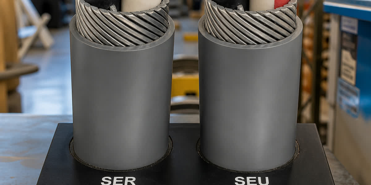
Los cables concéntricos usan alambres de cobre desnudo enrollados helicoidalmente directamente sobre el aislamiento (sirviendo como neutro y protección mecánica), mientras que los cables SWA usan alambres de acero galvanizado bajo una capa de asiento separada para armadura con un núcleo neutro separado. Los cables concéntricos son más ligeros, de menor diámetro y más fáciles de terminar.
P5: ¿Qué causa la corrosión del alambre neutro y cómo se detecta?
La corrosión es causada por la reacción electroquímica entre el cobre desnudo y los electrolitos transportados por la humedad del suelo (cloruros, sulfatos y pH ácido). Se acelera en zonas costeras (aerosol salino), áreas industriales (lluvia ácida) y suelos con pH < 5,5.
Sobre Sitong Cable
Sitong Cable es un fabricante profesional de cables con sede en Zhengzhou, China, con más de 30 años de experiencia produciendo cables concéntricos, cables de energía y conductores aéreos para redes de distribución de BT y MT en todo el mundo. Nuestros cables concéntricos se fabrican según las normas IEC 60502, BS 7870 e ICEA S-76-474, con aislamiento XLPE o PVC, conductores de cobre o aluminio, y alambres neutros estándar o estañados para cumplir con los requisitos ambientales de su proyecto.
👉 Explore nuestra gama de Cables Concéntricos → 👉 Vea todos los productos de Cable de Energía → 👉 Contacte a nuestro equipo de ingeniería →
Esta guía fue preparada por el equipo de ingeniería de Sitong Cable. Todos los datos técnicos referencian IEC 60502, BS 7870, ICEA S-76-474, IEEE 1185 e IEEE C62.92. Consulte siempre la norma aplicable para su jurisdicción específica antes de la instalación.