Bimetallic Cable Lugs & Shear Bolt Mechanical Connectors: Copper-to-Aluminum Transition Engineering, Galvanic Corrosion Prevention & High-Voltage Termination Guide
Bimetallic Cable Lugs & Shear Bolt Mechanical Connectors: Copper-to-Aluminum Transition Engineering, Galvanic Corrosion Prevention & High-Voltage Termination Guide
Terminating aluminum conductors to copper electrical equipment represents one of the most critical and failure-prone connection interfaces in electrical power engineering. When aluminum conductors—widely specified across overhead distribution, industrial switchgear, utility service drops, and renewable collector systems—are directly connected to copper busbars or apparatus studs without specialized transition hardware, severe joint degradation inevitably occurs. This degradation stems from three fundamental physical and chemical mechanisms: galvanic corrosion driven by high standard electrode potential differentials, differential thermal expansion coefficients inducing joint relaxation and thermal ratcheting, and rapid atmospheric oxidation forming non-conductive aluminum oxide (Al2O3) surface films.
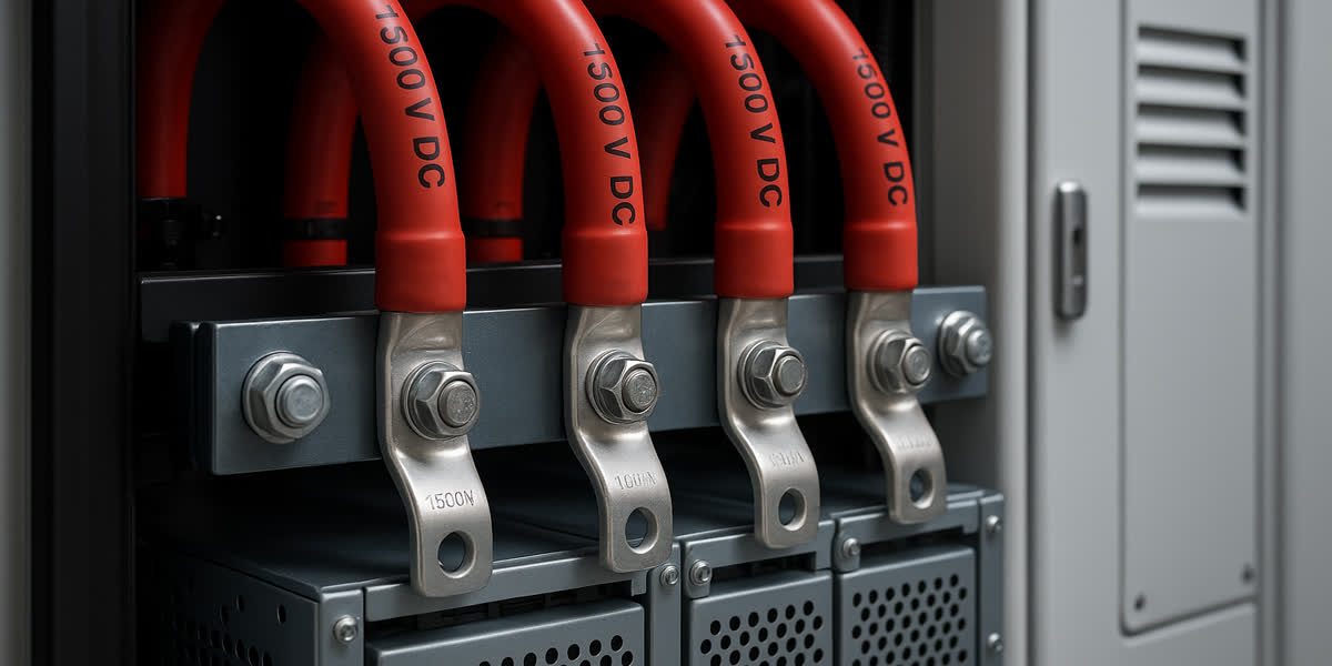
To guarantee lifetime electrical integrity, low contact resistance, and thermal stability under cyclic loading and short-circuit fault stresses, electrical utility engineers, EPC contractors, and industrial installers rely on engineered transition hardware: friction-welded bimetallic cable lugs (Cu-Al) and torque-controlled shear bolt mechanical connectors.
This comprehensive technical guide delivers deep engineering analysis into metallurgy, galvanic degradation physics, crimp mechanics, torque-controlled shear dynamics, international testing standards (IEC 61238-1, ANSI C119.4, DIN 46267, DIN 46235), and step-by-step installation methodologies for low, medium, and high-voltage power cable terminations.
+----------------------------------------------------------------------------------------------------+
|                COPPER-TO-ALUMINUM ELECTRICAL TERMINATION: FAILURE MECHANISMS VS SOLUTIONS          |
+----------------------------------------------------------------------------------------------------+
|                                                                                                    |
|  [DIRECT CU-AL CONTACT (HIGH RISK)]               [ENGINEERED BIMETALLIC TRANSITION (RELIABLE)]    |
|                                                                                                    |
|   Copper Busbar (+0.34V)                           Copper Switchgear Stud / Busbar                 |
|             |                                                     |                                |
|    (Moisture / Electrolyte)                               (Bolted Fastener Assembly)               |
|             |                                                     |                                |
|   Aluminum Conductor (-1.66V)                      +------------------------------+                |
|             |                                      | Copper Palm (100% Solid Cu)  |                |
|             v                                      +------------------------------+                |
|  [Galvanic Cell Formed]                                           | (Friction Weld Zone)           |
|  - Anodic oxidation of aluminum                                   v (Zero Void Diffusion Bond)     |
|  - Creep & thermal ratcheting                      +------------------------------+                |
|  - High-resistance Al2O3 layer                     | Aluminum Barrel (Solid Al)   |                |
|  - Thermal runaway & fire hazard                   +------------------------------+                |
|                                                                   | (Pre-filled Penetrox Compound) |
|                                                                   v                                |
|                                                    Aluminum / Alloy Power Conductor                |
+----------------------------------------------------------------------------------------------------+
1. Physical and Metallurgical Failure Mechanisms at Cu-Al Interfaces
Connecting dissimilar conductor metals involves severe electro-thermal and metallurgical challenges. Understanding these failure modes is essential for selecting appropriate terminal hardware.
1.1 Galvanic Corrosion Dynamics
When two electrochemically dissimilar metals are in direct contact in the presence of an electrolyte (atmospheric moisture, salt spray, industrial sulfur dioxides), an electrochemical galvanic cell is established: - Standard Reduction Potential: * Copper ($Cu \rightarrow Cu^{2+} + 2e^-$): $+0.34\text{ V}$ * Aluminum ($Al \rightarrow Al^{3+} + 3e^-$): $-1.66\text{ V}$ - Electrochemical Potential Difference: $\Delta E = 2.00\text{ V}$.
Because the potential difference vastly exceeds the standard galvanic threshold ($0.15\text{ V}$ for industrial/marine environments per MIL-STD-889), aluminum acts as a sacrificial sacrificial anode and undergoes rapid galvanic pitting and dissolution. The corrosion products—predominantly aluminum hydroxide ($Al(OH)_3$)—have electrical resistivity orders of magnitude higher than base metals, dramatically choking current flow across the interface and generating localized hot spots.
1.2 Thermal Expansion Mismatch and "Thermal Ratcheting"
Copper and aluminum exhibit significantly different coefficients of linear thermal expansion (CTE): - Aluminum: $\alpha \approx 23 \times 10^{-6}\text{ / K}$ - Copper: $\alpha \approx 16.5 \times 10^{-6}\text{ / K}$ - Steel (Standard Bolting Hardware): $\alpha \approx 11.5 \times 10^{-6}\text{ / K}$
During peak load cycles, conductor temperature rises from ambient to $90^\circ\text{C}$ (or $105^\circ\text{C}$ in overload conditions). The aluminum conductor expands roughly $40\%$ more than copper and twice as much as steel bolts. If restrained in a rigid, non-compliant bolted joint, the internal thermal compressive stress exceeds the yield strength of soft aluminum ($60\text{--}80\text{ MPa}$), causing plastic deformation and metallurgical creep.
When the electrical load drops and the connection cools, the yielded aluminum contracts, leaving microscopic interfacial air gaps. Atmospheric oxygen immediately enters, contact resistance rises, and the cycle repeats with compounding severity—a progressive failure phenomenon known as thermal ratcheting.
1.3 Instantaneous Aluminum Oxidation ($Al_2O_3$)
Within milliseconds of exposure to atmospheric air, virgin aluminum develops a transparent, refractory film of aluminum oxide ($Al_2O_3$) measuring $2\text{ to }10\text{ nanometers}$ in thickness. Aluminum oxide possesses exceptional dielectric insulation properties (dielectric strength $\approx 10^7\text{ V/m}$) and a melting point exceeding $2050^\circ\text{C}$. Unless mechanically ruptured and chemically inhibited during the jointing process, this oxide barrier restricts metallic contact to isolated microscopic asperities (a-spots), creating extreme constriction resistance ($R_c$).
2. Friction-Welded Bimetallic Lugs: Metallurgy and Architecture
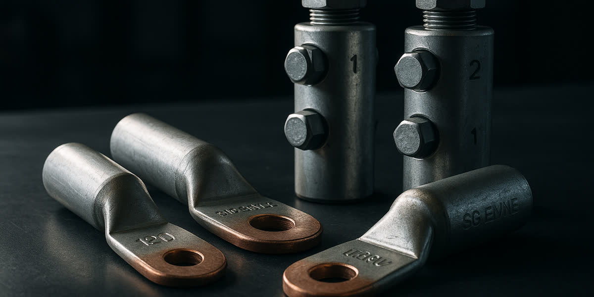
To permanently decouple the copper-aluminum galvanic interface from ambient atmospheric moisture, electrical equipment manufacturers specify solid friction-welded bimetallic cable lugs.
+----------------------------------------------------------------------------------------------------+
|               ANATOMY OF A HEAVY-DUTY FRICTION-WELDED BIMETALLIC CABLE LUG (DIN / IEC)             |
+----------------------------------------------------------------------------------------------------+
|                                                                                                    |
|    Inspection Hole: NONE                      Friction-Weld Joint Zone                             |
|    (Water-tight Sealed Barrel)                (Solid-State Diffusion, 100% Hermetic)               |
|            |                                           |                                           |
|            |    Aluminum Barrel (Al 99.5%)             |    Electrolytic Copper Palm (Cu-ETP 99.9%)|
|     +------+-------------------------------------------+-----+-------------------------------+     |
|     |                                                        |                               |     |
|  ==>|   [Internal Chamfer & Bore]                     =======|   (Stud Hole: M10 / M12 / M16)|(O)  |
|     |   Pre-filled with Contact Grease & Sand Grit           |                               |     |
|     +--------------------------------------------------+-----+-------------------------------+     |
|     <---------------- Barrel Length ------------------->     <--------- Palm Dimension ------>     |
|                                                                                                    |
+----------------------------------------------------------------------------------------------------+
2.1 Solid-State Friction Welding Process
In a certified bimetallic lug, the cylindrical aluminum barrel (extruded from high-purity electrical aluminum grade EC-Al 99.5% / 1050A) and the electrolytic copper palm (Cu-ETP / CW004A, 99.9% purity) are joined via continuous-drive rotary friction welding: 1. Friction Phase: The aluminum workpiece rotates at speeds exceeding $3000\text{ RPM}$ while being axially forced against the stationary copper palm under hydraulic pressure ($40\text{--}80\text{ MPa}$). 2. Plasticization: Interfacial friction generates temperatures between $450^\circ\text{C}$ and $500^\circ\text{C}$, softening the metals into a viscoplastic state without melting them. 3. Upset Forging: Rotation is abruptly braked, and a massive axial upset forging force ($120\text{--}200\text{ MPa}$) is applied. This expels interfacial oxides and contaminants radially outward in a flash collar, establishing a 100% molecular diffusion bond. 4. Hermetic Enclosure: The resulting molecular Cu-Al transition is contained completely within solid metal, isolating it from moisture and ambient electrolytes. Galvanic corrosion at the weld plane is physically impossible.
2.2 Barrel Geometry and Contact Aid Pre-filling
High-performance cable lugs and bimetallic terminals incorporate specific design features: - Blind, Water-Tight Barrel: Unlike standard copper lugs, bimetallic lugs have a closed-end solid barrier between the barrel and palm to prevent water ingress along stranded conductors. - Factory Pre-filling with Inhibitor Compound: Barrels are factory pre-filled with high-temperature neutral synthetic grease suspension (e.g., polybutene or silicon-based) containing sharp, microscopic silicon carbide or zinc abrasive particles. During conductor insertion and crimping, the grease excludes air while the abrasive particles rupture the insulating $Al_2O_3$ surface skin on individual conductor strands. - Color-Coded End Plugs: Protect the contact grease from drying or contamination prior to assembly.
3. Shear Bolt Mechanical Connectors: Friction-Free Precision Jointing
While compression lugs provide robust service, their long-term reliability is heavily dependent on craft skill, correct die selection, and hydraulic tool calibration. Over-crimping damages conductor strands, while under-crimping leads to elevated joint resistance.
To eliminate installer-induced variance, the global utility industry has adopted torque-controlled shear bolt mechanical connectors and lugs for low and medium-voltage distribution systems.
+----------------------------------------------------------------------------------------------------+
|               STEPLESS SHEAR BOLT MECHANICAL CONNECTOR OPERATIONAL PRINCIPLE                       |
+----------------------------------------------------------------------------------------------------+
|                                                                                                    |
|    1. Conductor Insertion               2. Tightening with Hex Wrench         3. Stepless Shearing |
|                                                                                                    |
|       [Hex Drive Head]                     [Hex Drive Head]                                        |
|             |                                    |                                                 |
|       (Shear Groove)                       (Shear Groove)                                          |
|             |                                    | (Pre-set Torque)                                |
|       [Threaded Stud]                      [Threaded Stud]                                         |
|             |                                    | (Penetrates Strands)                            |
|             v                                    v                                                 |
|    +-----------------+                  +-----------------+                  +-----------------+   |
|    |  Aluminum Body  |                  |  Aluminum Body  |                  |  Aluminum Body  |   |
|    |  (High-Strength |                  |                 |                  |                 |   |
|    |   AlSi1MgMn)    |                  |  ~~~~~~~~~~~~~  |                  |  ~~~~~~~~~~~~~  |   |
|    |                 |                  |  =============  |                  |  =============  |   |
|    |  Conductor Core |                  |  Conductor Core |                  |  Conductor Core |   |
|    +-----------------+                  +-----------------+                  +-----------------+   |
|                                                                              [Flush with Body]     |
|                                                                                                    |
+----------------------------------------------------------------------------------------------------+
3.1 Stepless vs Multi-Tier Shear Bolt Technology
Modern mechanical shear bolt lugs feature high-tensile brass or aluminum-alloy bolts with engineered shear points: - Multi-Groove Bolts: Feature pre-machined circumferential notches calibrated to shear off at specific torque levels (e.g., $25\text{ N}\cdot\text{m}$, $45\text{ N}\cdot\text{m}$, $70\text{ N}\cdot\text{m}$) depending on the conductor diameter inserted. - Stepless Friction-Shear Bolts: The apex of connector engineering. The inner threaded bolt body features a friction-clutch mechanism that shears precisely flush with the connector housing body, regardless of whether a minimum size ($25\text{ mm}^2$) or maximum size ($300\text{ mm}^2$) conductor is inserted. This leaves zero protruding bolt head, eliminating the need to file or wrap sharp metal edges prior to installing heat-shrink or cold-shrink insulation tubes.
3.2 Grooved Inner Barrel Bore
The internal bore of shear bolt connectors features precision circumferential micro-grooving. As the shear bolt descends under massive torque, the concentrated point load drives the cable strands downward into the housing grooves, cold-welding strand surfaces, breaking oxide layers, and establishing gas-tight contact zones across the entire circumference.
4. Engineering Comparison: Compression Lugs vs. Shear Bolt Connectors
Specifying engineers must weigh tooling capital expenditure, inventory standardization, installer training, and technical performance when selecting termination hardware:
| Performance & Engineering Parameter | Friction-Welded Bimetallic Compression Lugs | Stepless Shear Bolt Mechanical Lugs | Standard Electro-Tinned Copper Lugs |
|---|---|---|---|
| Applicable Conductor Range | Specific single cross-section (e.g. $185\text{ mm}^2$) | Wide range-taking (e.g. $95\text{--}240\text{ mm}^2$) | Specific single cross-section |
| Supported Conductor Material | Pure Aluminum, Aluminum Alloys | Al, Cu, Solid, Stranded, Compacted, Flexible | Copper only (Al restricted) |
| Tooling Required | Calibrated hydraulic crimper + matched dies | Standard impact socket or manual ratchet wrench | Calibrated hydraulic crimper |
| Operator Error Sensitivity | High (incorrect die or stroke ruins joint) | Extremely Low (torque shears automatically) | High |
| Oxide Film Penetration | Rely on manual wire-brushing + grease grit | Built-in high-pressure shear + grooved housing | Inadequate for aluminum conductors |
| Installed Profile | Smooth hexagonal crimp profile | Flush shear; no sharp protrusions | Smooth hexagonal crimp profile |
| Installed Labor Time | $4\text{--}6\text{ minutes}$ per termination | $1\text{--}2\text{ minutes}$ per termination | $3\text{--}5\text{ minutes}$ per termination |
| Material Cost per Unit | Moderate ($) | Higher ($$$) | Lower ($) |
| Inventory SKU Count | Massive (one SKU per conductor size) | Minimal (3 SKUs cover $25\text{ to }630\text{ mm}^2$) | Massive |
| International Standard Compliance | IEC 61238-1 Class A, DIN 46235 / DIN 46267 | IEC 61238-1 Class A, ANSI C119.4 Class A | IEC 61238-1, BS 7609 |
For utility overhead lines and distribution circuits utilizing all-aluminum conductors (AAC) and aluminum conductor alloy reinforced (ACAR), shear bolt connectors provide unmatched speed and consistency during substation connections and transformer tapping.
5. Cable Sizing and Lug Selection Cross-Reference Matrix
Selecting correct lug geometry and crimp parameters is vital to avoid mechanical pullout or thermal overheating. The following matrix cross-references metric and imperial conductors against bimetallic lug and shear bolt specifications:
| Nominal Conductor Size | Conductor Stranding Type | Recommended Bimetallic Lug Barrel Bore (mm) | Recommended Hex Die Width / Code (DIN 48083) | Shear Bolt Range Designation | Min Pull-out Tensile Force (IEC 61238-1) |
|---|---|---|---|---|---|
| $25\text{ mm}^2$ (4 AWG) | Compacted / Round Stranded | $6.8\text{ mm}$ | Die No. 12 | Range: $25\text{--}95\text{ mm}^2$ | $1.25\text{ kN}$ |
| $50\text{ mm}^2$ (1/0 AWG) | Stranded / Sector Compacted | $9.8\text{ mm}$ | Die No. 16 | Range: $25\text{--}95\text{ mm}^2$ | $2.50\text{ kN}$ |
| $95\text{ mm}^2$ (3/0 AWG) | Compacted Class 2 | $13.2\text{ mm}$ | Die No. 22 | Range: $95\text{--}240\text{ mm}^2$ | $4.75\text{ kN}$ |
| $150\text{ mm}^2$ (300 kcmil) | Compressed / Compacted | $16.5\text{ mm}$ | Die No. 25 | Range: $95\text{--}240\text{ mm}^2$ | $7.50\text{ kN}$ |
| $240\text{ mm}^2$ (500 kcmil) | Compacted Class 2 | $21.0\text{ mm}$ | Die No. 32 | Range: $95\text{--}240\text{ mm}^2$ | $12.00\text{ kN}$ |
| $300\text{ mm}^2$ (600 kcmil) | Compacted Class 2 | $23.5\text{ mm}$ | Die No. 34 | Range: $120\text{--}300\text{ mm}^2$ | $15.00\text{ kN}$ |
| $400\text{ mm}^2$ (800 kcmil) | Compacted Class 2 | $26.8\text{ mm}$ | Die No. 38 | Range: $185\text{--}400\text{ mm}^2$ | $20.00\text{ kN}$ |
| $500\text{ mm}^2$ (1000 kcmil) | Segmental / Compacted | $30.0\text{ mm}$ | Die No. 42 | Range: $300\text{--}630\text{ mm}^2$ | $25.00\text{ kN}$ |
| $630\text{ mm}^2$ (1250 kcmil) | Milliken / Segmental | $34.5\text{ mm}$ | Die No. 44 | Range: $300\text{--}630\text{ mm}^2$ | $31.50\text{ kN}$ |
6. International Qualification Standards: Class A Electrical and Mechanical Testing
To be approved for critical utility transmission, industrial distribution, and renewable generation installations, bimetallic lugs and mechanical connectors must pass rigorous type tests defined by IEC 61238-1-1 (for compression connectors) and IEC 61238-1-3 (for mechanical shear bolt connectors).
+----------------------------------------------------------------------------------------------------+
|                  IEC 61238-1 CLASS A COMPREHENSIVE ELECTRICAL TESTING CYCLE                        |
+----------------------------------------------------------------------------------------------------+
|                                                                                                    |
|  [Initial Joint Resistance: R_0]                                                                   |
|              |                                                                                     |
|              v                                                                                     |
|  [1000 Current Heating Cycles] ===> (Conductor heated to 120°C; held for 15 min; force-cooled)     |
|              |                                                                                     |
|              v (Intermittent Short-Circuit Tests)                                                  |
|  [6 Short-Circuit Current Surges] => (Applied at Cycle 200; Conductor heated to 250°C in <= 1 sec) |
|              |                                                                                     |
|              v                                                                                     |
|  [Pass Criteria Verification]:                                                                     |
|  1. Resistance Factor: k <= 2.0 throughout all 1000 cycles                                         |
|  2. Joint Temperature: T_joint <= T_reference_conductor                                            |
|  3. Resistance Scatter: D <= 0.15 (High stability, zero thermal runaway)                          |
+----------------------------------------------------------------------------------------------------+
6.1 Class A vs Class B Certification
- Class A Connectors: Mandatory for distribution and transmission networks subject to prospective short-circuit faults. Connectors must endure 1000 thermal heat cycles followed by six massive short-circuit current surges that raise the conductor temperature to $250^\circ\text{C}$ within 1 second. Joint temperature throughout the test must remain lower than the reference conductor temperature ($T_{joint} \le T_{ref}$).
- Class B Connectors: Intended only for circuits protected by rapid current-limiting devices where short-circuit duties are strictly curtailed (heat cycling only, no short-circuit impulse).
6.2 Pull-out Tensile Testing
Following electrical cycling, test specimens must maintain mechanical tensile integrity without conductor slip, achieving minimum pullout forces defined by: $$F = 60 \times A \quad (\text{Newtons for Aluminum Conductors})$$ (where $A$ is the nominal cross-sectional area in $\text{mm}^2$, up to a maximum cap of $40\text{ kN}$).
7. Step-by-Step Field Installation Engineering Protocols
Even premium-grade bimetallic terminals fail if installed with sub-standard field practices. Installers must adhere to the following sequence:
7.1 Cable Stripping and Preparation
- Insulation Stripping: Using a precision circumferential cable stripper, remove cable insulation cleanly without nicking, scoring, or cutting any conductor strands. Strip length must equal the lug barrel bore depth plus $5\text{ mm}$ to allow for conductor elongation during crimping.
- Radial Oxide Stripping: For bare aluminum and alloy conductors like AAAC conductor systems and ACSR bare conductors, thoroughly wire-brush the exposed conductor core using a stainless steel wire brush. Brush radially and longitudinally for at least 30 seconds to abrade the tough $Al_2O_3$ film.
- Immediate Grease Sealing: Immediately coat the abraded strands with certified electrical joint antioxidant compound before atmospheric oxygen can re-passivate the surface.
7.2 Crimp Execution for Compression Lugs
- Die Selection: Select precision hexagonal dies matching the conductor diameter and DIN standard code marked on the lug barrel.
- Crimping Direction (Crucial): Always crimp starting from the palm end and progressing toward the open barrel mouth. Crimping in reverse traps air and causes internal metal wave buckling.
- Full Pressure Dwell: Hold hydraulic compression until the tool bypass valve activates ($700\text{ bar}$ continuous hydraulic pressure).
- Flash Removal & Cleaning: Wipe away extruded excess joint compound and deburr any sharp aluminum fins created along die parting lines to prevent electrical field concentration in medium-voltage power cables.
CRIMPING SEQUENCE (MANDATORY):
[Palm / Weld Zone]  ===>  [Crimp 1]  ===>  [Crimp 2]  ===>  [Crimp 3]  ===>  [Cable Entry]
                    (Directs material elongation outward toward the cable)
7.3 Bolted Flange Fastener Engineering
When bolting the copper palm of a bimetallic lug to switchgear terminals, transformer bushings, or busbar arrays, standard hardware practices must be enforced: - Fastener Metallurgy: Utilize Grade 8.8 high-tensile zinc-plated steel or 316 stainless steel bolts. - Belleville Conical Spring Washers: Standard flat split-lock washers fail under continuous thermal expansion. Always install hardened conical Belleville spring washers (DIN 6796) beneath the nut. The Belleville washer acts as an elastic spring reservoir, compensating for thermal expansion cycles and maintaining constant contact pressure ($15\text{--}25\text{ MPa}$). - Calibrated Torque Wrench: Tighten bolts to pre-determined torque limits: * M10 Bolt: $40\text{--}45\text{ N}\cdot\text{m}$ * M12 Bolt: $70\text{--}80\text{ N}\cdot\text{m}$ * M16 Bolt: $170\text{--}190\text{ N}\cdot\text{m}$ - Fastener and Support Hardware: Ensure all surrounding cable supports, cleat brackets, and suspension fittings and hardware are correctly anchored to prevent cantilever vibrations from transmitting into the termination interface.
8. Manufacturing Excellence and Supply Ecosystem: SiTong Cable
Since 2010, SiTong Cable (Zhengzhou Sitong Cable Co., Ltd.) has provided world-class power transmission, distribution, and industrial cabling infrastructures to utilities, EPC contractors, and global power authorities across more than 80 countries.
Integrated Cable & Hardware Systems
A transmission or distribution cable system is only as reliable as its weakest joint. SiTong Cable eliminates interoperability risks by manufacturing and supplying fully matched, type-tested conductor and connector assemblies: - High-Precision Friction Welding Facilities: Our accessory manufacturing plants utilize multi-axis automated CNC friction welding cells equipped with dynamic torque and acoustic emission monitors, verifying 100% molecular bond density and zero internal porosity on every bimetallic lug. - Electrolytic Copper Purity: Lugs and terminals feature Cu-ETP copper ($99.9\% \text{ IACS conductivity}$) with precision chemical electro-tin plating to prevent tarnishing in sulfur-rich environments. - Full Compatibility with Conductor Families: Whether deploying compact aluminum aerial bundled cables (ABC), low-voltage underground direct-burial cables, or utility building and feeder wires, SiTong engineers provide pre-calibrated lug, die, and connector packages guaranteed to exceed IEC 61238 Class A requirements. - In-House High-Voltage Laboratory: Full thermal cycling, salt fog corrosion chambers, and impulse current surge equipment ensure all products perform reliably through 30+ year service lives under extreme climatic conditions.
9. Frequently Asked Questions (FAQ)
Q1: Can I connect an aluminum conductor to a copper busbar using a standard electro-tinned copper lug?
Answer: While electro-tinned copper lugs are widely used in low-amperage, dry indoor residential applications, they are strongly discouraged for commercial, industrial, and utility-scale installations. The mechanical thermal expansion rate of aluminum conductor strands is significantly higher than that of the copper lug barrel. Under cyclic heavy electrical loads, the softer aluminum strands yield and creep inside the rigid copper barrel, resulting in joint loosening, elevated resistance, and localized fire hazards. For reliable, code-compliant connections, always specify solid friction-welded bimetallic Cu-Al lugs or stepless shear bolt mechanical lugs.
Q2: Why is the friction-welded bimetallic joint placed between the barrel and palm rather than inside the barrel?
Answer: Placing the friction weld interface between the solid barrel and the flat palm ensures that the molecular junction between copper and aluminum is 100% solid, non-porous, and physically isolated from the interior cable chamber. This prevents ambient moisture or corrosive gases from reaching the dissimilar metal interface. The conductor strands contact only the aluminum barrel, eliminating any galvanic cell inside the crimp zone.
Q3: What is the primary operational advantage of shear bolt connectors over hydraulic crimp lugs?
Answer: The primary advantage is the complete elimination of installer tooling errors and die mismatch. Shear bolt connectors are engineered with calibrated shear heads that automatically snap off at the exact torque required for optimal gas-tight contact, regardless of operator physical strength or tool battery charge. Additionally, a single shear bolt connector covers multiple conductor sizes (wide range-taking capability), substantially reducing warehouse inventory SKUs and eliminating the need to transport heavy hydraulic crimpers and dozens of die sets into remote field locations.
Q4: Do bimetallic cable lugs require special Belleville washers during busbar installation?
Answer: Yes. When bolting a bimetallic lug palm to an equipment terminal or busbar, the assembly is subject to continuous temperature swings between no-load and full-load states. Standard flat washers or split lock washers cannot accommodate the differential thermal expansion between the steel bolt, copper palm, and aluminum or copper busbar. Conical Belleville spring washers (compliant with DIN 6796) flex elastically under load, maintaining constant contact clamping pressure ($15\text{--}25\text{ MPa}$) and preventing thermal ratcheting and contact resistance escalation.
Q5: How should aluminum conductor surfaces be treated before inserting into a bimetallic lug?
Answer: Aluminum surfaces instantaneously develop a tough, insulating aluminum oxide ($Al_2O_3$) film when exposed to air. Before termination, the conductor core must be vigorously cleaned with a stainless steel wire brush to abrade and break this oxide layer. An approved antioxidant joint compound (often pre-filled inside quality bimetallic lug barrels) must be applied immediately to seal the freshly cleaned aluminum strands and prevent atmospheric re-oxidation.
10. Summary and Engineering Support
Safe, lifetime copper-to-aluminum power cable terminations require rigorous attention to metallurgy, thermal expansion dynamics, and galvanic protection. By engineering terminations with friction-welded bimetallic lugs and precision torque-controlled shear bolt connectors, power engineers eliminate interface degradation, minimize maintenance costs, and ensure absolute operational safety across utility grids and industrial plants.
SiTong Cable provides global energy utilities, EPC contractors, and industrial developers with comprehensive technical consultation, customized cable design, and certified cable accessories tailored to meet international grid codes and project specifications.
👉 Explore our Complete Range of Cable Lugs, Terminals and Bimetallic Connectors
👉 Discover Engineered Power Transmission Fittings and Hardware
👉 Browse Low and Medium Voltage Power Cables for Industrial and Utility Grids
👉 Contact SiTong Cable Engineering Specialists for Custom Technical Submittals
📬 Sales and Technical Inquiries: sales@sitongcable.com | 📞 Phone / WhatsApp: +86-371-69176007