Battery Energy Storage System (BESS) Cable Sizing and Engineering Guide: 1500V DC Bus, Short-Circuit Thermal Limits, Ampacity Derating and BMS Cabling
Battery Energy Storage System (BESS) Cable Sizing and Engineering Guide: 1500V DC Bus, Short-Circuit Thermal Limits, Ampacity Derating and BMS Cabling
Battery Energy Storage Systems (BESS) require specialized electrical cabling engineered to withstand high continuous DC currents, severe thermal accumulation within compact enclosures, and massive prospective DC short-circuit discharge currents. As utility-scale energy storage plants migrate from legacy 1000V DC architectures to high-efficiency 1500V DC platforms, system engineers must design cabling infrastructures that guarantee negligible voltage drop, resist chemical electrolyte exposure, suppress electromagnetic interference (EMI) from power conversion systems (PCS), and comply with stringent international safety standards including IEC 62930, EN 50618, UL 4127, and NFPA 855.
This engineering guide provides utility engineers, balance-of-system (BOS) designers, EPC contractors, and system integrators with comprehensive, data-driven methodologies for sizing and specifying BESS cabling across DC battery modules, containerized DC busbars, bi-directional inverters, and medium-voltage grid interconnections.
+----------------------------------------------------------------------------------------------------+
|                         UTILITY-SCALE BESS COMPLETE ELECTRICAL CABLING ARCHITECTURE                |
+----------------------------------------------------------------------------------------------------+
|                                                                                                    |
|  [Battery Rack Module 1]  [Battery Rack Module 2] ... [Battery Rack Module N] (1500V DC Series)    |
|             |                           |                           |                              |
|             +-------------+-------------+---------------------------+                              |
|                           | (Flexible Class 5 Tinned Cu / Cross-linked XLPO)                       |
|                           v                                                                        |
|                 [DC Combiner and Disconnect Panel]                                                 |
|                           |                                                                        |
|                           | (Heavy-Duty 1500V DC Bus Feeder Cable)                                 |
|                           v                                                                        |
|            [Power Conversion System (PCS) Bi-directional Inverter]                                 |
|                           |                                                                        |
|                           +--------> [BMS / EMS Controller] <--- (Shielded Control Cables)         |
|                           |                                                                        |
|                           | (Low-Voltage AC Output: 690V / 800V)                                   |
|                           v                                                                        |
|                 [Step-Up Transformer (e.g. 0.8kV / 33kV)]                                          |
|                           |                                                                        |
|                           | (Medium Voltage Armoured Underground Power Cable)                      |
|                           v                                                                        |
|                 [Substation Switchgear and Utility High-Voltage Grid Intertie]                     |
|                                                                                                    |
|  [Perimeter Earthing Grid: Galvanized Steel Grounding Strands and Equipotential Ground Clamps]     |
+----------------------------------------------------------------------------------------------------+
1. Electrical Architecture and Cabling Subsystems in Utility-Scale BESS
A modern grid-scale BESS facility comprises four primary electrical zones, each subject to distinct operating voltages, current dynamics, and environmental stresses:
1.1 Intra-Rack Module Interconnects (Cell-to-Cell and Module-to-Module)
- Voltage: 48V to 1500V DC floating or center-grounded.
- Operating Environment: Confined battery rack corridors with limited convective airflow, ambient operating temperatures reaching 40°C to 50°C during heavy charge/discharge cycles.
- Cable Construction: Flexible Class 5 or Class 6 fine-stranded tinned copper conductors insulated with electron-beam cross-linked polyolefin (XLPO). High flexibility (tight bending radius of 4x to 6x outer diameter) is mandatory to accommodate narrow rack clearances and vibration during seismic or transport events.
- Standard Product Selection: For modular DC string connections, EPCs rely on certified solar and DC energy storage cables built with dual-layer halogen-free cross-linked insulation rated for 1500V DC continuous service.
1.2 DC Main Busbar and Collector Feeders (Rack to Combiner / Inverter)
- Operating Current: 250A to 600A per battery string; multiple strings parallel-connected to deliver up to 2000A–4000A to central inverters.
- Primary Challenges: Severe continuous I2R resistive heating, proximity effect in closely spaced multi-cable trays, and direct exposure to prospective fault currents exceeding 50kA.
- Design Requirement: Single-core cables with robust flame-retardant, low-smoke zero-halogen (LSZH) outer sheaths to prevent flame propagation along cable trays per IEC 60332-3-24 (Cat C) or UL 1685.
1.3 Power Conversion System (PCS) to Step-Up Transformer (Low-Voltage AC)
- Voltage: Typically 600V, 690V, or 800V three-phase AC.
- Harmonic Distortion: High-frequency PWM ripple generated by IGBT or SiC switching bridges, requiring heavy-duty single-core or three-core flexible copper/aluminum medium-voltage power cables and low-voltage feeders designed to handle harmonic skin effect derating.
1.4 Auxiliary, Safety and Battery Management System (BMS) Networks
- Signals: Modbus TCP, CANbus, RS-485, analog temperature sensing (RTD/NTC), and emergency power-off (EPO) trip loops.
- Risk: High electromagnetic interference (EMI) radiated from switching inverters and DC bus transients can corrupt sensor telemetry and induce false thermal runaway alarms.
- Specification: Multi-pair individually and overall shielded (IS/OS) shielded control cables with 100% aluminum-mylar tape plus high-coverage tinned copper braided screening.
2. International Standards and Technical Specification Matrix
Specifying cables for utility-scale energy storage requires adherence to modern international standards covering 1500V DC ratings, flame retardancy, and toxic gas elimination:
| Parameter | IEC 62930 / EN 50618 | UL 4127 / UL 4703 | IEC 60502-1 / IEC 60502-2 |
|---|---|---|---|
| Applicable Domain | DC Storage & Photovoltaics | BESS Racks & Solar BOS | LV & MV Collector Feeders |
| Rated Voltage (Uo/U) | 1.5/1.5 kV DC (1.8 kV Max) | 1000V / 2000V DC (UL Listed) | 0.6/1.0 kV to 18/30 (36) kV |
| Conductor Material | Class 5 Flexible Tinned Copper | Class B / Class K Flexible Cu | Class 2 Compacted Al / Cu |
| Insulation Material | Dual Cross-linked XLPO | XLPE or EPR (90°C / 105°C) | XLPE / TR-XLPE / EPR |
| Max Conductor Temp | 90°C Continuous (120°C for 20,000h) | 90°C Dry/Wet (105°C Optional) | 90°C Continuous, 250°C Short-Circuit |
| Flame Retardancy | IEC 60332-1-2 / EN 50399 | VW-1 / FT4 Vertical Tray Flame | IEC 60332-1 / IEC 60332-3-22 |
| Halogen Acid Content | Zero Halogen (<0.5% HCl per IEC 60754) | Optional LSZH Rating | Non-halogenated or LSZH variants |
| Chemical Resistance | Acid / Alkaline / Ozone / UV | Oil Resistant I & II (UL 1277) | Hydrocarbon / Water Impervious |
Under NFPA 855 (Standard for the Installation of Stationary Energy Storage Systems), all intra-container cabling must minimize fire loading, prevent toxic gas accumulation during off-gas venting events, and maintain circuit integrity for emergency shutdown systems.
3. Conductor Sizing Methodology and Engineering Calculations
Proper cable sizing in a BESS installation balances three distinct physical constraints: continuous thermal ampacity, maximum permissible voltage drop, and adiabatic short-circuit withstand.
+-----------------------------------------------------------------------------------------+
|                       BESS CABLE SIZING THREE-TIER SELECTION LOGIC                      |
+-----------------------------------------------------------------------------------------+
|                                                                                         |
|  [Step 1: Continuous Ampacity]                                                          |
|  Calculate I_rated = P_string / V_min_DC                                                |
|  Apply Derating: I_allowable = I_table * k_ambient * k_grouping * k_enclosure           |
|  Ensure: I_allowable >= 1.25 * I_rated                                                  |
|                                |                                                        |
|                                v                                                        |
|  [Step 2: Voltage Drop Verification]                                                    |
|  Delta_V = (2 * I_rated * L * rho_temp) / S                                             |
|  Ensure: Delta_V <= 1.0% (DC Bus) or <= 1.5% (Total String to Inverter)                 |
|                                |                                                        |
|                                v                                                        |
|  [Step 3: DC Short-Circuit Adiabatic Capacity]                                          |
|  Calculate Prospective Fault: I_sc_DC = V_open_circuit / (R_battery + R_cable + R_fuse) |
|  Calculate Minimum Area: S_min = (I_sc * sqrt(t_clear)) / k_material                    |
|  Ensure: S_selected >= max(S_thermal, S_vdrop, S_shortcircuit)                          |
+-----------------------------------------------------------------------------------------+
3.1 Continuous DC Full-Load Current and Thermal Derating
The rated continuous current (I_rated) for a battery string must be calculated at the lowest operating DC discharge cut-off voltage (V_min):
I_rated = P_string / V_min
Because BESS containers operate with internal ambient temperatures often exceeding 40°C despite HVAC systems, and cables are grouped densely in horizontal and vertical raceways, thermal derating factors must be applied:
I_z = I_0 * k_t * k_g * k_c
Where:
- I_0 = Nominal cable ampacity from standard tables (IEC 60364-5-52 or NEC Table 310.16) at reference temperature (30°C or 40°C).
- k_t = Ambient temperature correction factor. For a 90°C XLPO cable operating in a 45°C container enclosure, k_t = 0.82 (IEC) or 0.87 (NEC).
- k_g = Multi-conductor grouping derating factor (e.g., 6 circuits in touching horizontal tray: k_g = 0.72).
- k_c = Enclosure conduit / unventilated raceway factor (0.85–0.90).
Example: A 250A rated string feeder installed in a crowded tray inside a 45°C container requires an un-derated cable ampacity of:
I_0 >= (250 A * 1.25) / (0.82 * 0.72 * 0.90) = 588.6 A
This dictates parallel conductor runs or sizing up to a 300 mm2 flexible single-core conductor.
3.2 DC Voltage Drop Optimization
In battery storage systems, excessive voltage drop results in wasted round-trip efficiency (RTE), battery imbalance, premature low-voltage cut-off, and localized thermal hot spots. For a two-wire DC circuit, the voltage drop is calculated as:
Delta_V = (2 * L * I * rho_T) / S
Where:
- L = One-way circuit length (meters).
- I = Maximum continuous direct current (Amperes).
- rho_T = Conductor resistivity at operating temperature (for copper at 90°C, rho_90 = 0.0224 Ohm*mm2/m).
- S = Conductor cross-sectional area (mm2).
Standard Design Criterion: Delta_V from the farthest battery module to the PCS DC input bus must not exceed 1.0% at nominal system voltage (15V drop max on a 1500V bus).
3.3 Prospective DC Short-Circuit Adiabatic Withstand
Unlike AC short-circuit faults that benefit from natural current zero-crossings every half cycle (10ms at 50Hz), direct-current faults from lithium-ion battery banks exhibit zero natural crossings. A prospective bolted DC short circuit at the string terminals discharges the combined capacitive and electrochemical energy of the cells with sub-millisecond rise times (di/dt > 10 kA/ms), reaching peak fault currents of 20kA to 60kA.
Before the fast-acting DC semiconductor or pyrotechnic fuse clears (typically within t_k = 5 ms to 20 ms), the cable conductor must absorb the full adiabatic thermal energy without exceeding the 250°C insulation damage threshold.
The minimum conductor cross-section (S_min) based on adiabatic thermal limits is calculated per IEC 60364-5-54:
S_min = (I_sc * sqrt(t_k)) / k
Where:
- I_sc = Effective prospective DC short-circuit current (RMS equivalent, Amperes).
- t_k = Total fault clearance time of the protective device (seconds).
- k = Thermal material factor (for copper conductors with XLPO/XLPE insulation, k = 143 A*s^0.5/mm2).
| Prospective DC Fault (I_sc) | Clearing Time (t_k) | Adiabatic Energy (I2t) | Min Conductor Size (S_min) | Recommended Standard Size |
|---|---|---|---|---|
| 15 kA | 10 ms (0.010 s) | 2.25 x 10^6 A2s | 10.49 mm2 | 16 mm2 |
| 25 kA | 10 ms (0.010 s) | 6.25 x 10^6 A2s | 17.48 mm2 | 25 mm2 |
| 35 kA | 15 ms (0.015 s) | 1.84 x 10^7 A2s | 29.98 mm2 | 35 mm2 |
| 50 kA | 20 ms (0.020 s) | 5.00 x 10^7 A2s | 49.44 mm2 | 70 mm2 |
| 70 kA | 20 ms (0.020 s) | 9.80 x 10^7 A2s | 69.21 mm2 | 95 mm2 |
Engineering Warning: While a 25 mm2 cable might satisfy nominal ampacity for a small 100A auxiliary rack, a prospective 50kA busbar fault will vaporize the conductor within 15ms if the backup fuse clearing time exceeds coordination limits. The larger of S_thermal, S_vdrop, and S_min must always govern selection.
4. Insulation Material Selection: XLPO vs. Silicone vs. Traditional PVC/EPR
Inside an enclosed BESS energy storage container, fire safety and environmental stability are non-negotiable. Traditional PVC insulation is entirely prohibited in utility-grade containers due to the release of lethal hydrogen chloride (HCl) gas when thermally stressed, which forms hydrochloric acid upon contact with moisture, irreparably destroying delicate electronic PCBs and battery management modules.
+------------------------------------------------------------------------------------+
|                         BESS INSULATION PERFORMANCE COMPARISON                     |
+------------------------------------------------------------------------------------+
|                                                                                    |
|  Material     Temp Rating    Halogen Content    Dielectric Strength   Acid/Oil Res |
|  --------------------------------------------------------------------------------  |
|  PVC          70°C - 90°C    High (>15% HCl)    Moderate (~20 kV/mm)  Poor         |
|  Silicone     180°C - 200°C  Zero Halogen       High (~25 kV/mm)      Moderate/Soft|
|  EPR/CSP      90°C           Zero/Low Halogen   Good (~22 kV/mm)      Good         |
|  XLPO (E-beam)90°C - 120°C   Zero (<0.2% HCl)   Superior (>32 kV/mm)  Excellent    |
+------------------------------------------------------------------------------------+
Why Electron-Beam Cross-Linked Polyolefin (XLPO) Is the Industry Standard:
- Three-Dimensional Molecular Web: Electron-beam irradiation cross-links the polyolefin chains into a thermoset matrix, preventing melting or flow even at short-circuit temperatures up to 250°C.
- Superior Dielectric Endurance under DC Stress: High-voltage direct current causes persistent unidirectional charge accumulation within dielectric materials (space charge). Cross-linked polyolefins maintain high volume resistivity (> 10^14 Ohm*cm) without dielectric breakdown.
- Electrolyte and Chemical Resistance: In the unlikely event of lithium-ion cell off-gassing or electrolyte leakage (containing dimethyl carbonate, ethylene carbonate, and trace hydrofluoric acid HF), XLPO sheaths prevent polymer degradation and conductor corrosion.
- Abrasion Resistance: Unlike soft silicone insulation which tears easily against sheet metal rack corners during pulling, XLPO provides high mechanical cut-through and crush resistance.
5. Electromagnetic Compatibility (EMC) and BMS Control Wiring
A BESS container represents an exceptionally harsh electromagnetic environment. Multi-megawatt Power Conversion Systems utilize high-speed insulated-gate bipolar transistors (IGBTs) or silicon carbide (SiC) MOSFETs switching at frequencies between 2 kHz and 20 kHz. The resulting steep voltage rise times (dv/dt > 5 kV/us) induce high-frequency common-mode voltages and radiated electromagnetic fields across adjacent control trays.
Critical Engineering Guidelines for BMS Signal Integrity:
- Twisted-Pair Geometry: Communication lines for CANbus and RS-485 must utilize tightly twisted pairs (lay length < 50 mm) to cancel magnetically induced differential noise.
- Dual-Layer Shielding (IS/OS): Utilize shielded control cables featuring an inner aluminum/polyester tape foil with tinned copper drain wire, complemented by an overall tinned copper braid with >= 85% optical coverage.
- Physical Separation: In accordance with IEEE 518 and IEC 61000-5-2, maintain a minimum physical clearance of 300 mm between DC power feeders and analog sensor cables in parallel tray runs. When crossings are unavoidable, cross strictly at a 90 degree perpendicular angle.
- Shield Grounding Best Practice: Ground high-frequency BMS communication cable shields via 360-degree circumferential EMC glands at the enclosure entry point, rather than using long pigtails which introduce substantial inductive impedance (L ~ 1 uH/m) that invalidates high-frequency shielding.
6. Earthing, Grounding Grids and Medium-Voltage Grid Intertie
Utility-scale BESS sites combine low-voltage DC batteries, medium-voltage AC equipment, and sensitive telemetry inside metallic containers mounted on concrete pads. Comprehensive grounding protects personnel from touch and step potentials during catastrophic internal cell ground faults or external lightning strikes.
+------------------------------------------------------------------------------------------+
|                     BESS CONTAINER GROUNDING & SUBSTATION TIE TOPOLOGY                   |
+------------------------------------------------------------------------------------------+
|                                                                                          |
|       [BESS Container Steel Frame]             [BESS Container Steel Frame]              |
|                    |                                        |                            |
|                    +--- [Equipotential Earth Jumper] -------+                            |
|                    |                                        |                            |
|                    v                                        v                            |
|  ======================================================================================  |
|         Site Perimeter Grounding Grid: Hot-Dip Galvanized Steel Strands (ASTM A475)      |
|  ======================================================================================  |
|          |                            |                           |                      |
|          v                            v                           v                      |
|    [Deep Ground Rod]            [MV Step-Up Trans.]         [Substation Switchgear]      |
|                                       |                           |                      |
|                                       +==== (MV Power Cable) =====+                      |
|                                       |     Direct Burial XLPE                           |
+------------------------------------------------------------------------------------------+
6.1 Perimeter Earthing and Lightning Dissipation
Because standard copper earthing tape in remote utility-scale solar+storage installations is highly vulnerable to metal theft and galvanic corrosion when in contact with galvanized steel structures, international project designers specify heavy-duty galvanized steel wire strands (ASTM A475 Class A or BS 183) for the perimeter ring grid and counterpoise dissipation. Galvanized steel provides robust short-circuit earth fault capacity, matching the cathodic potential of container foundations and structural piles.
6.2 Medium-Voltage Interconnection
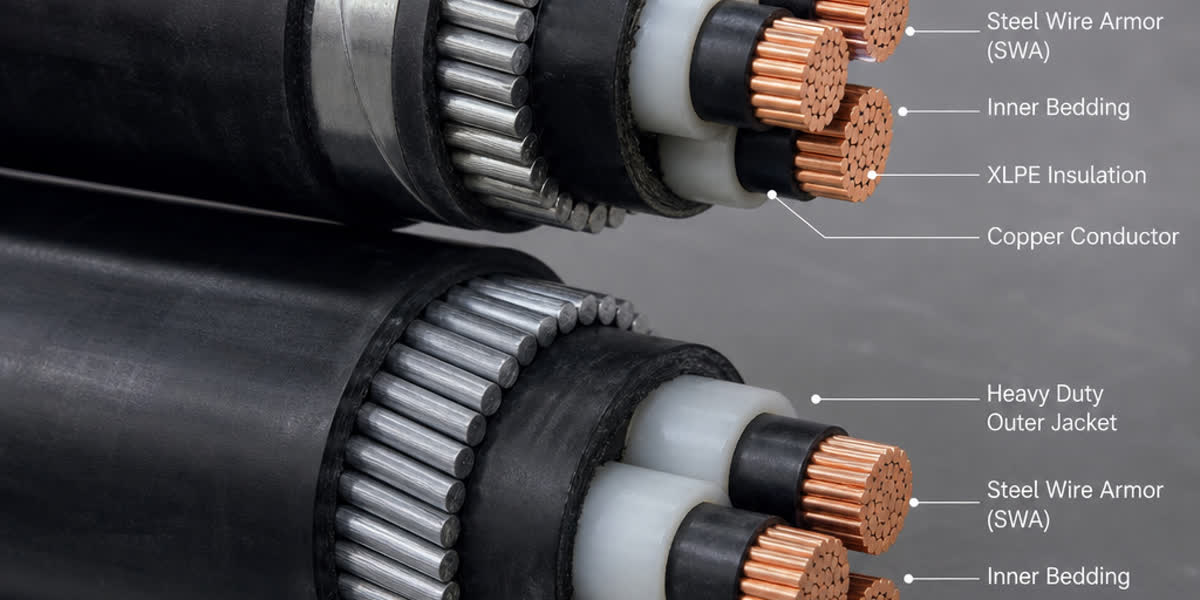
From the BESS container step-up transformer (typically 0.8kV to 33kV or 34.5kV), power is transmitted to the project substation using three-core or single-core triplexed direct burial underground cables or armoured medium-voltage power cables with copper wire screens sized per IEC 60502-2 to carry system earth-fault currents without thermal damage.
7. Cable Termination, Lug Crimping and Thermal Validation
Field analysis reveals that more than 65% of electrical failures and thermal runaways in BESS DC cabinets originate not within the cable insulation, but at improperly crimped or torqued terminal interfaces.
Critical Termination Rules:
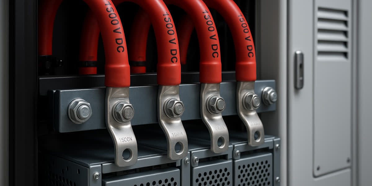
- Bimetallic and Tinned Connections: Because DC busbars are typically silver- or tin-plated copper and battery terminals may feature aluminum/copper alloys, always install electro-tinned heavy-duty compression cable lugs manufactured from 99.9% high-conductivity electrolytic copper per DIN 46235.
- Hexagonal Compression Dies: Avoid indent crimping for high-amperage DC battery feeds. Hexagonal compression dies ensure symmetrical compaction of Class 5 flexible stranded conductors, expelling air pockets and achieving a low contact resistance (< 10 micro-ohms).
- Belleville Spring Washers: Lithium-ion battery racks experience continuous cyclic thermal expansion and contraction during charge/discharge cycles. All terminal bolting must utilize Grade 8.8 steel or stainless hardware fitted with conical Belleville spring washers to maintain constant contact pressure under thermal cycling.
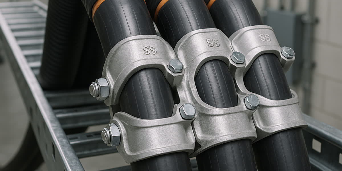
- Cable Restraint and Strain Relief: Secure cables using non-magnetic, flame-retardant cable hardware fittings and mounting accessories placed within 300 mm of terminations to eliminate mechanical shear forces on battery module bushings.
- Thermographic Baseline Inspection: During commissioning at 100% continuous C-rate discharge, conduct baseline FLIR infrared thermal imaging. Any terminal displaying a temperature rise (Delta_T) greater than 5°C relative to the adjacent cable conductor must be immediately retorqued or remade.
8. Quality Assurance and Manufacturing Excellence: SiTong Cable
As a dedicated global cable manufacturer since 2010, SiTong Cable (Zhengzhou Sitong Cable Co., Ltd.) supplies premium cabling solutions for utility-scale solar, wind, and battery energy storage projects across more than 80 countries in Southeast Asia, the Middle East, Africa, Europe, and the Americas.
Why Tier-1 EPCs Specify SiTong Cable for BESS Infrastructure:
- Advanced Electron-Beam Irradiation: State-of-the-art dual-tube electron accelerators guarantee 100% uniform cross-linking across our entire 1500V DC energy storage cable line, delivering continuous 120°C thermal ratings and superior short-circuit withstand.
- High-Purity Oxygen-Free Copper: We utilize pure cathode copper (purity >= 99.97%) with multi-wire in-line electro-tinning, preventing copper oxidation and reducing contact resistance in humid, salty, or industrial atmospheres.
- Stringent Vertical Flame and Smoke Testing: In-house optical smoke density chambers and vertical tray burn rigs certify full compliance with IEC 60332-3-24 (Cat C), IEC 61034 (smoke density >= 70% light transmittance), and IEC 60754-1/2 zero-halogen standards.
- Comprehensive Product Ecosystem: From flexible 1500V DC string cables and BMS multi-core shielded control cables to 35kV armored medium-voltage underground cables and galvanized steel ground strands, SiTong delivers an integrated balance-of-system (BOS) cabling package.
9. Frequently Asked Questions (FAQ)
Q1: Can standard PV1-F solar cable be used for BESS battery rack wiring?
Answer: While legacy PV1-F (TÜV 2 PfG 1169) cables share similarities with modern DC cables, utility-scale BESS applications demand cables certified to IEC 62930 or EN 50618 (H1Z2Z2-K), and in North America, UL 4127 / UL 4703. Modern BESS standards enforce stricter flame retardancy under bunched tray configurations (IEC 60332-3-24), superior acid/alkaline chemical resistance against battery off-gas, and enhanced long-term thermal endurance under continuous 120°C conditions. Standard PV1-F should not be substituted for containerized BESS DC string wiring without verifying vertical tray burn compliance and UL/IEC energy storage ratings.
Q2: Why is fine-stranded Class 5 copper conductor mandatory over Class 2 rigid copper inside BESS enclosures?
Answer: Class 5 flexible stranding consists of numerous fine-gauge wires (e.g., hundreds of 0.25mm–0.40mm wires) compared to the 7, 19, or 37 rigid strands of Class 2 conductors. In compact BESS containers, tight bending radii (down to 4x OD) are required to navigate confined rack pathways without stressing battery module terminal bushings. Furthermore, flexible Class 5 conductors withstand mechanical vibrations during transport and seismic shaking without work-hardening or cracking.
Q3: How do you prevent circulating currents when paralleling single-core 1500V DC cables?
Answer: When running multiple single-core cables in parallel per polarity (e.g., three 240 mm2 cables per positive and negative bus), ensure identical physical cable lengths, matching conductor cross-sections, and identical terminal crimp resistances to prevent unbalanced current sharing. Route positive and negative cables in close proximity or alternating trefoil arrangements to minimize loop inductance and magnetic field emissions. Non-magnetic (aluminum or polymeric) cable cleats must be used to eliminate eddy current heating in metal supports.
Q4: What is the recommended maximum voltage drop for BESS DC cabling?
Answer: Good engineering practice dictates a maximum voltage drop of 1.0% across the main DC collector busbars and no more than 1.5% for the total circuit from the farthest battery cell module to the PCS inverter DC terminals. Lower voltage drop directly enhances round-trip efficiency (RTE) over the plant’s 15–25 year life, minimizes heat dissipation inside the air-conditioned container, and prevents premature inverter under-voltage tripping during high C-rate discharge pulses.
Q5: How should the metallic shields of BMS control cables be grounded in a BESS container?
Answer: BMS control cable shields should be grounded using 360-degree circumferential EMC shield clamps at the cabinet entry gland plate. This provides a low-impedance path to earth for high-frequency electromagnetic noise generated by inverter IGBT switching. Grounding via long pigtail wires should be avoided, as their high parasitic inductance degrades shielding effectiveness at frequencies above 100 kHz.
10. Conclusion and Project Engineering Support
Engineering cabling for 1500V DC Battery Energy Storage Systems requires a holistic balance of thermal modeling, prospective DC fault current calculations, strict material fire safety compliance (LSZH / XLPO), and electromagnetic compatibility. By selecting certified, high-grade conductors and engineered accessories, system developers maximize operational availability, optimize round-trip efficiency, and safeguard facilities against catastrophic thermal events.
SiTong Cable provides global energy storage developers, EPC contractors, and equipment manufacturers with complete technical specification support, custom cable manufacturing, and certified electrical accessories tailored to international grid standards.
👉 Explore our Solar PV and DC Energy Storage Cable Range
👉 Browse Shielded Control and Instrumentation Cables for BMS Networks
👉 Contact SiTong Cable Engineering Team for Custom BESS Specifications
📬 Sales and Project Inquiries: sales@sitongcable.com | 📞 Phone / WhatsApp: +86-371-69176007