Concentric Cable Installation & Maintenance: Complete Field Guide for LV & MV Distribution Networks

2026-07-20 | Sitong Cable Engineering Team | technical
Concentric Cable Installation & Maintenance: Complete Field Guide for LV & MV Distribution Networks

Concentric Cable Installation & Maintenance: Complete Field Guide for LV & MV Distribution Networks

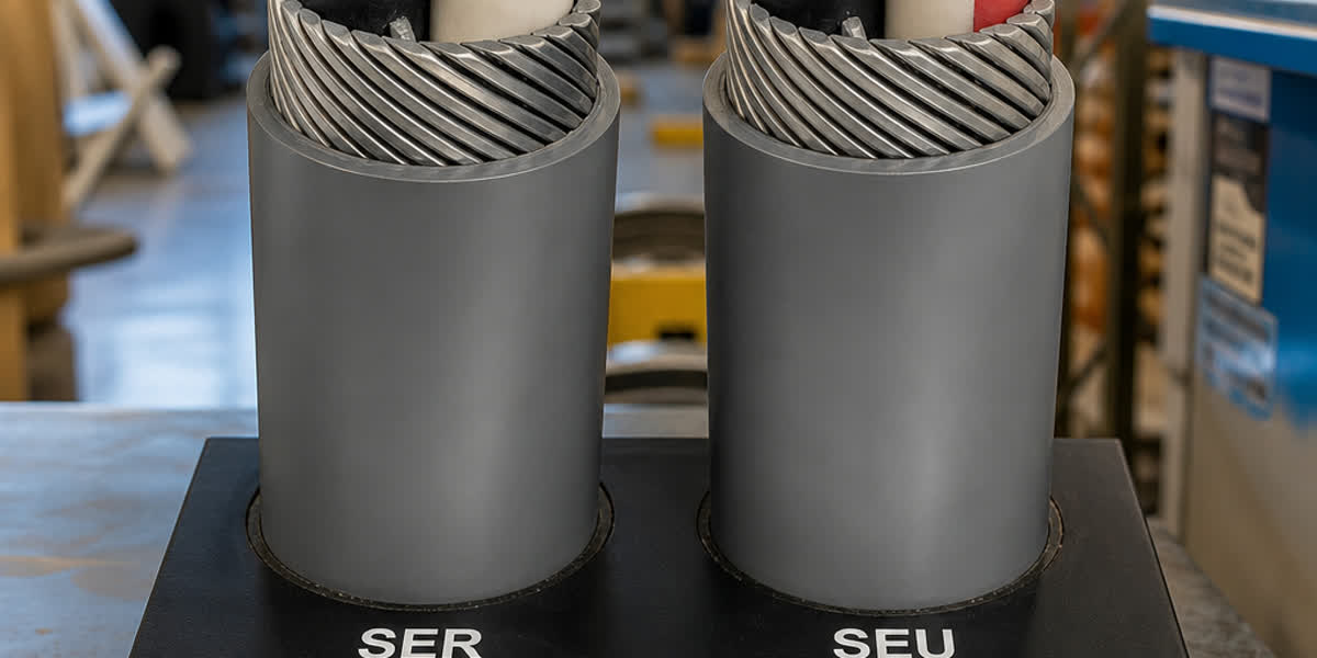
Concentric cables are widely used in low-voltage (0.6/1 kV) and medium-voltage (6.6/11 kV to 19/33 kV) underground distribution networks worldwide, prized for their integrated neutral design that combines the neutral/ground conductor and mechanical protection into a single helical wire layer. This design reduces trench width by 30–50% and installation labor by up to 40% compared with multi-cable bundled systems. However, the unique concentric neutral construction also introduces distinct installation and maintenance challenges — from proper bending radius control to neutral wire corrosion management.

This field guide is intended for electrical contractors, utility linemen, site engineers, and maintenance crews who install and maintain concentric cables in the field. It covers pre-installation preparation, pulling and laying procedures, splicing and termination techniques, inspection and testing protocols, routine maintenance schedules, and common troubleshooting scenarios, all referenced to the applicable international standards.

Pre-Installation Preparation

Proper preparation before the cable arrives on site prevents the most common installation defects — mechanical damage, moisture ingress, and incorrect bending.

Receiving and Storage Checklist

Inspection Item Acceptance Criteria Action on Non-Conformance
Drum condition No cracks, broken flanges, or protruding nails Photograph and reject; request replacement drum
Cable end seals Both ends sealed with non-hygroscopic caps; no moisture visible Remove and re-seal with heat-shrink caps; log for warranty
Sheath visual inspection No cuts, abrasions, or kinks along visible cable length Measure depth; if >10% of sheath thickness, cut back and re-terminate
Conductor resistance measurement DC resistance ≤ IEC 60228 maximum per cross-section Reject batch if any drum exceeds limit
Insulation resistance (Megger) LV: ≥100 MΩ/km at 500 V DC; MV: ≥1000 MΩ/km at 2.5 kV DC Dry out or replace; do not install wet cable
Neutral wire continuity Helical wires continuous, no broken strands Repair or replace affected section
Drum rotation direction Marked with arrow; cable pays off top of drum Re-orient drum stand before pulling

Tools and Equipment Checklist

Tool Category Required Equipment Application Notes
Pulling Cable pulling grip (basket weave or Kellems grip), swivel, pulling rope (polypropylene, minimum 2× safety factor), pulling lubricant (water-based, compatible with PE/PVC sheath) Never pull by the concentric neutral wires — always pull by the conductor using a basket grip applied over the sheath
Bending Cable rollers (straight and corner), bend radius templates (minimum 12× OD for LV, 15× OD for MV) Pre-set corner rollers at required radius before pulling
Cutting Ratchet cable cutter (hydraulic for ≥240 mm²), hacksaw with fine-tooth blade (for neutral wires only) Abrasive wheels generate heat that damages XLPE insulation
Stripping Semi-conductive layer stripping tool, insulation stripper (adjustable depth), cable knife For MV: use semi-conductive stripping tool to avoid nicking the insulation
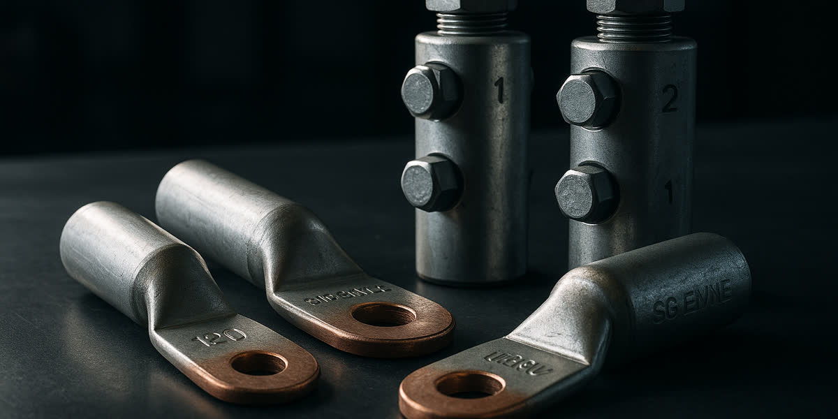
Termination Compression dies (matching lug/connector manufacturer specifications), torque wrench, heat gun (for heat-shrink terminations) Verify die closure matches connector width per manufacturer spec
Testing Insulation resistance tester (Megger 5 kV for MV), DC Hi-Pot tester, TDR (Time Domain Reflectometer) Calibrate annually per ISO 17025

Environmental Conditions

Ambient temperature during cable pulling should be above 0 °C (32 °F) for PE-sheathed cables and above −5 °C (23 °F) for PVC-sheathed cables. Below these temperatures, the sheath becomes brittle and prone to cracking during bending. If installation in cold weather is unavoidable, pre-warm the cable drum in a heated enclosure at 15–25 °C for a minimum of 24 hours before pulling.

⚠️ Cold Weather Warning: Never use a torch or direct flame to warm a cable drum. Use forced warm air heating only.

Engineering Calculations for Installation

Two critical calculations must be performed before any concentric cable pull: maximum pulling tension and minimum bending radius.

Maximum Pulling Tension

The maximum pulling tension for a concentric cable is governed by the conductor and the neutral wires. The formula per IEEE 1185 and ICEA P-54-440 is:

T_max = C × A × n

Where: - T_max = maximum allowable pulling tension (N) - C = conductor constant (copper: 70 N/mm²; aluminium: 40 N/mm²) - A = cross-sectional area of a single conductor (mm²) - n = number of conductors (typically 1 for single-core concentric cable)

Example: A 1-core 95 mm² aluminium concentric cable: T_max = 40 × 95 × 1 = 3800 N (approximately 387 kgf)

💡 Rule of Thumb: Never exceed 3800 N (≈387 kgf) for aluminium conductor concentric cables up to 95 mm². For copper conductors, the limit rises to approximately 6650 N for 95 mm².

Pulling tension must be monitored with a dynamometer or tension meter during pulling. If tension exceeds 80% of T_max, stop and investigate — the likely cause is a sidewall pressure problem.

Sidewall Pressure

Sidewall pressure (SWP) is the force exerted by the cable against a bend roller or duct corner:

SWP = T / R

Where: - SWP = sidewall pressure (N/m) - T = tension at the bend (N) - R = bend radius (m)

Maximum SWP for concentric cables: 3650 N/m for PE jacket, 2900 N/m for PVC jacket per ICEA S-76-474.

Minimum Bending Radius

Per IEC 60502 and BS 7870:

Cable Type Minimum Bending Radius (during installation)
LV Concentric (0.6/1 kV), PVC sheath 10 × overall diameter
LV Concentric (0.6/1 kV), PE sheath 12 × overall diameter
MV Concentric (11 kV), XLPE insulated 15 × overall diameter
MV Concentric (33 kV), XLPE insulated 20 × overall diameter
After installation (all types) 8 × overall diameter

⚠️ Warning: Bending beyond these limits can cause the concentric neutral wires to lift away from the insulation screen, creating voids that lead to partial discharge failure in MV cables.

Installation Procedure — Step by Step

Step 1: Trench Preparation and Duct Installation

Dig a trench with minimum width of 300 mm for single cables and 450 mm for multiple cables laid side by side. Trench depth per IEC 60364-5-52 and NEC Table 300.5:

Voltage Direct Burial Depth Duct Bank Depth
LV (0.6/1 kV) 600 mm 450 mm
MV (11 kV) 900 mm 750 mm
MV (33 kV) 1200 mm 1000 mm

Lay 100 mm of screened sand or fine soil (max particle size 10 mm) as a bedding layer. Install warning tape 300 mm above the cable.

Step 2: Cable Drum Positioning and Unreeling

Position the drum so the cable pays off from the top of the drum. Mount the drum on a hydraulic jack or spindle stand that allows free rotation. Use a brake system to prevent over-run — uncontrolled pay-off causes kinking.

🏗️ Best Practice: Never unreel cable from a stationary drum by pulling — this induces torsion that damages the concentric neutral lay. Always use a rotating drum stand.

Step 3: Pulling the Cable

  1. Attach the basket weave pulling grip over the cable sheath — never over the neutral wires alone.
  2. Connect a swivel between the pulling grip and the pulling rope to prevent twisting.
  3. Apply pulling lubricant uniformly along the entire pull length, especially at entry points and bends.
  4. Pull at a steady speed of 3–6 m/min for LV, 2–4 m/min for MV. Excessive speed generates frictional heat and can damage the sheath.
  5. Monitor pulling tension continuously. Record peak tension at each bend and at the end of the pull.

Step 4: Cable Laying and Snaking

In trenched installations, lay the cable with slight snaking (approximately 2–3% extra length) to accommodate thermal expansion and soil settlement. For direct burial, the cable should rest on the bedding layer in a gentle S-curve rather than a straight line.

Step 5: Splicing and Termination

Concentric cable joints and terminations must preserve the integrity of both the insulation system and the concentric neutral path.

LV Concentric Cable Termination (per BS 7870-1):

Step Operation Tooling Verification
1 Strip outer sheath to expose neutral wires Sheath stripper, depth set to sheath thickness No scoring of neutral wires
2 Unwind neutral wires and fan out Hand tools Wires not stretched or nicked
3 Strip insulation to expose conductor Insulation stripper Conductor clean, no nicks
4 Install lug or connector Compression tool + correct die Die closure meets manufacturer spec
5 Fold neutral wires back over sheath and terminate to neutral bus Connector sized for aggregate neutral cross-section All neutral wires terminated

MV Concentric Cable Termination (per IEC 60502-2):

Step Operation Tooling Verification
1 Strip outer sheath and neutral wires Sheath stripper Neutral wires intact
2 Remove outer semi-conductive layer Semi-con stripping tool No residue, clean surface
3 Strip XLPE insulation Insulation stripper Clean, smooth surface; no stress raisers
4 Install stress cone (pre-molded or cold-shrink) Installation kit Visual: cone centered on insulation screen cut
5 Install lug and reconnect neutral wires Compression + neutral connector Electrical continuity across neutral path
6 Apply outer jacket (cold-shrink or heat-shrink) Heat gun or cold-shrink core Seal is watertight

⚠️ Critical: For MV concentric cables, the semi-conductive layer cut must be absolutely clean — any protrusion creates a stress concentration point that will cause partial discharge failure within months.

Step 6: Backfilling and Compaction

Backfill with screened sand or fine soil free of stones (max particle size 10 mm) in 150 mm layers, compacting each layer with hand tampers. Install mechanical protection tiles or concrete slabs if the cable runs under roadways or heavy traffic areas.

Post-Installation Inspection & Testing

Test Item LV Concentric Cable MV Concentric Cable Acceptance Criteria
Visual inspection Entire accessible length Entire accessible length No sheath damage, kinks, or sharp bends below minimum radius
Insulation resistance (Megger) 500 V DC, 1 minute 5 kV DC, 1 minute LV: ≥100 MΩ; MV: ≥1000 MΩ
DC Hi-Pot test Not typically required 4 × Uo, 15 minutes No breakdown or leakage current surge
Conductor continuity Low-resistance ohmmeter Low-resistance ohmmeter <5% above calculated round-trip resistance
Neutral wire continuity Visual + ohmmeter Visual + ohmmeter All neutral wires continuous; contact resistance <0.1 Ω per joint
Partial discharge (PD) Not required Per IEC 60270 ≤10 pC at 1.7 × Uo for XLPE insulation
Sheath integrity test 5 kV DC spark test 10 kV DC spark test No spark-through

Routine Maintenance Schedule

Frequency LV Concentric Cable MV Concentric Cable
Monthly Visual inspection of accessible terminations Visual inspection of terminations; infrared scanning of all joints
Quarterly Check neutral wire connections at service boxes for corrosion PD measurement at critical joints (if PD sensors installed)
Annually Sample insulation resistance on 10% of circuits Full set of insulation resistance + DC Hi-Pot on all circuits
Every 3 years Thermal imaging of entire cable route (accessible sections)
Every 5 years Corrosion check of neutral wires at sample terminations Dissipation factor (tan δ) measurement — trend analysis
Every 10 years Replace terminations showing corrosion Replace stress cones; full PD mapping

Neutral Wire Corrosion Management

The most common failure mode in concentric cables is corrosion of the bare copper neutral wires, particularly in coastal, industrial, and acidic soil environments. The helical wire design creates small crevices where moisture and pollutants accumulate.

Recommended Practices: - In corrosive soil (pH < 5.5 or resistivity < 2000 Ω·cm): specify tinned copper neutral wires or a flooded neutral design with anticorrosion compound - In coastal installations (< 5 km from salt water): apply neutral wire corrosion inhibitor gel at all terminations and joints - Bi-annual thermal imaging of neutral wire connections at service points — a temperature rise of >15 °C above ambient indicates developing high-resistance corrosion

Troubleshooting Common Issues

Problem Likely Cause Diagnostic Method Solution
Insulation resistance below limit Moisture ingress through damaged sheath Megger test + locate moisture entry point with TDR Cut back and re-terminate beyond moisture; dry out if necessary
Neutral wire open circuit Corrosion break or mechanical damage at termination Visual inspection + ohmmeter continuity check Replace termination; evaluate if cathodic protection is needed
Partial discharge (MV) Semi-conductive layer cut damage or void at stress cone PD measurement per IEC 60270 Replace stress cone; re-prepare the termination
Sheath pinhole failure Stone puncture during backfill 5 kV spark test along route Excavate, repair with heat-shrink sleeve; install mechanical protection
Overheating at service connection High-resistance neutral wire corrosion Infrared thermography Clean and re-terminate with antioxidant compound
Cable pulling tension exceeded limit Kinked duct or crushed bend roller Dynamometer review; camera inspection of duct Reduce pulling speed; if tension > T_max, extract cable and re-pull
Bending radius violation Sharp duct bend or corner roller set too tight Bend radius template Excavate and correct the bend; replace cable section if kinked
LV neutral hum/buzzing Loose neutral connection → harmonic currents Current clamp measurement on neutral Tighten connection; verify neutral-to-phase current ratio

Safety Considerations

Hazard Precaution Relevant Standard
Induced voltage on concentric neutral when one end is open Bond and ground neutral at both ends during installation; use insulated gloves IEEE 524, EN 50110-1
Cable drum tipping during unreeling Use drum jacks on level ground; chock wheels OSHA 29 CFR 1910.180
Stored energy in capacitive MV cable Confirm cable is discharged and grounded before handling — MV cables hold charge for hours IEC 60895
Pulling wire whip on rope break Use pulling rope with 3× safety factor; keep personnel clear of tension line OSHA 1926.955
Hot surfaces from infrared inspection Maintain minimum distance per equipment manufacturer specification NFPA 70E
Underground services strike during trenching Use CAT (Cable Avoidance Tool) scan before any excavation HSG47 (UK), OSHA 1926.651

Frequently Asked Questions

Q1: What is the typical lifespan of a concentric cable installation?

Properly installed concentric cables with XLPE insulation have a service life of 30–40 years for LV and up to 40–50 years for MV applications per CIGRE TB 279. The limiting factor is usually the concentric neutral wires rather than the insulation — corrosion of the bare copper wires accelerates in aggressive soil or coastal environments.

Q2: How do I identify the correct concentric cable size for a new service entrance?

Follow the four-step framework: (1) determine load current from connected load, (2) apply derating factors for depth, soil resistivity, and grouping (per IEC 60364-5-52 or NEC Table 310.15), (3) size neutral wires to carry 100% of the load current plus harmonic content, and (4) verify voltage drop (<3% recommended). Refer to the Concentric Cable Complete Technical Guide for detailed sizing tables.

Q3: Can concentric cable be installed in conduit?

Yes, but conduit fill must not exceed 40% per NEC Chapter 9 Table 1. Use sweeps (long-radius bends) rather than standard 90° elbows to maintain the minimum bending radius. Pulling lubricant is essential — concentric cables have a larger effective diameter than round cables of equivalent ampacity due to the neutral wire layer.

Q4: How is a concentric cable different from a conventional SWA (steel wire armored) cable?

Concentric cables use bare copper helical neutral wires wrapped directly over the insulation (serving as both neutral and mechanical protection), while SWA cables use galvanized steel wires under a separate bedding layer for armor with a separate neutral core. Concentric cables are lighter, smaller in diameter, and easier to terminate — but SWA cables provide superior crush resistance for heavy industrial environments and direct-impact scenarios.

Q5: What causes neutral wire corrosion and how is it detected?

Corrosion is caused by electrochemical reaction between bare copper and moisture-borne electrolytes in the soil (chlorides, sulfates, and acidic pH). It is accelerated in coastal zones (salt spray), industrial areas (acid rain), and soils with pH < 5.5. Detection methods include: (1) ohmmeter continuity check — a resistance increase >20% above as-installed values indicates developing corrosion, (2) infrared thermography — hot spots at terminations indicate high-resistance corroded connections, and (3) sample excavation at representative locations every 5 years. For new installations in corrosive environments, specify tinned copper neutral wires or a flooded neutral design with corrosion inhibitor.

Q6: What is the correct procedure for bonding the concentric neutral at both ends?

Per IEC 60364-4-44 and IEEE C62.92, the concentric neutral must be bonded to the grounding electrode at both the source and load ends for LV systems. For MV systems, the neutral is typically bonded only at the source end and isolated at the load end (single-point bonding) to limit circulating currents. Always verify with the utility's grounding policy before installation.

Q7: Can concentric cables be installed in parallel to increase ampacity?

Yes, up to 4 cables in parallel per phase is permitted by IEC 60364-5-52 and NEC 310.10(H). However, current sharing depends on identical impedance per parallel path — use cables of the same length, type, and cross-section. De-rating factors for grouping (typically 0.8 for 4 cables in a single trench) must be applied. Unequal impedance sharing causes one cable to carry disproportionate current and overheat.

Q8: What is the difference between a concentric cable and a screened (shielded) power cable?

A concentric cable uses bare wires as neutral conductors wrapped helically over the insulation — these serve as both the neutral return path and mechanical protection. A screened/shielded power cable uses a thin copper tape, wire screen, or semi-conductive layer specifically for electric field containment and fault current return — it does not serve as a neutral. Screened cables are required for voltages above 3.6/6 kV per IEC 60502-2; concentric cables are more common at LV and MV distribution voltages where the neutral function is needed.

Standards Reference

Standard Description
IEC 60502-1 Power cables with extruded insulation — LV (0.6/1 kV and 3/3.6 kV)
IEC 60502-2 Power cables with extruded insulation — MV (6/6 kV to 19/33 kV)
BS 7870-1 LV polymeric insulated cables for utilities — Concentric neutral types
BS 7870-2 MV polymeric insulated cables for utilities — Concentric neutral types
ICEA S-76-474 Neutral-spaced power cables (USA standard)
UL 1277 Electrical power and control tray cables
IEEE 1185 Recommended practice for cable pulling
ICEA P-54-440 Ampacities of cables installed in underground ducts
IEC 60364-5-52 Low voltage electrical installations — Selection and erection of wiring systems
IEC 60840 Power cables with extruded insulation for voltages >30 kV (test methods)
IEC 60270 High voltage test techniques — Partial discharge measurements
IEEE C62.92 Neutral grounding guide
CIGRE TB 279 Service life of power cables

About Sitong Cable

Sitong Cable is a professional cable manufacturer based in Zhengzhou, China, with over 30 years of experience producing concentric cables, power cables, and overhead conductors for LV and MV distribution networks worldwide. Our concentric cables are manufactured to IEC 60502, BS 7870, and ICEA S-76-474 standards, with XLPE or PVC insulation, copper or aluminium conductors, and standard or tinned copper neutral wires to meet your project's environmental requirements.

👉 Browse our Concentric Cable range → 👉 Explore all Power Cable products → 👉 Contact our engineering team →

This guide was prepared by the Sitong Cable engineering team. All technical data references IEC 60502, BS 7870, ICEA S-76-474, IEEE 1185, and IEEE C62.92. Always consult the relevant standard for your specific jurisdiction before installation.