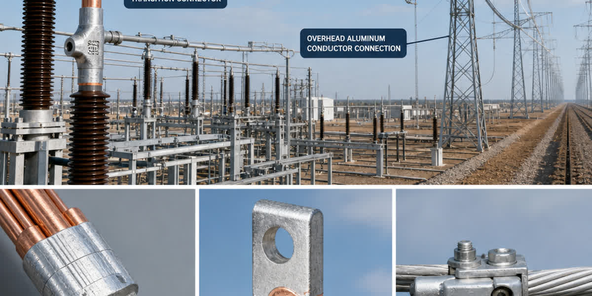
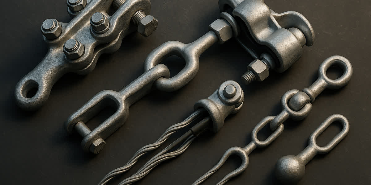
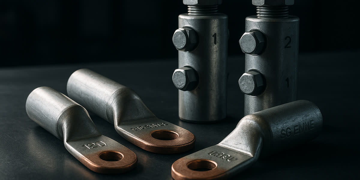
Conductor AAC (Conductor de Aluminio Desnudo) — Guía Técnica Completa: Normas BS 215, IEC 61089 y ASTM B231, Especificaciones, Selección y Aplicaciones en Líneas Eléctricas Aéreas
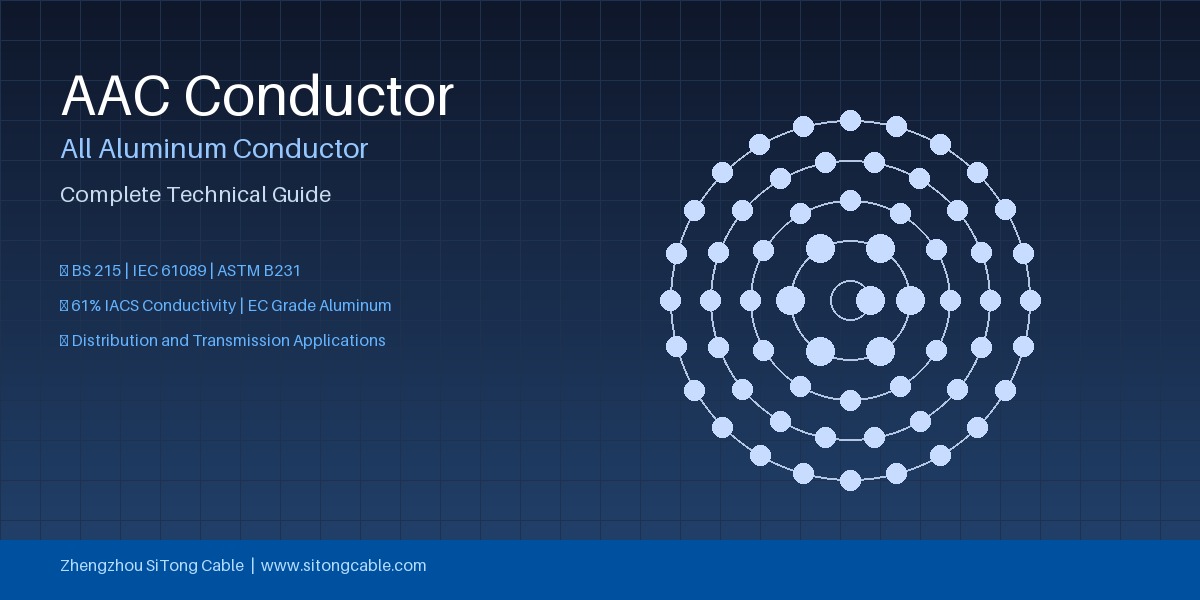
Conductor AAC (Conductor de Aluminio Desnudo) — Guía Técnica Completa: Normas BS 215, IEC 61089 y ASTM B231, Especificaciones, Selección y Aplicaciones en Líneas Eléctricas Aéreas
El conductor de aluminio desnudo (AAC, por sus siglas en inglés) es el tipo de conductor aéreo desnudo más original y ampliamente utilizado, compuesto por múltiples capas de alambres de aluminio trenzados de grado EC (Conductividad Eléctrica). AAC ofrece la relación más alta de conductividad a peso entre todos los conductores aéreos comunes, lo que lo convierte en la opción preferida para líneas de distribución de corta a media distancia, redes urbanas y regiones con cargas ambientales moderadas. Esta guía técnica integral cubre la construcción del conductor AAC, las normas internacionales (BS 215, IEC 61089, ASTM B231), las especificaciones eléctricas y mecánicas, la metodología de selección y las aplicaciones reales en sistemas de transmisión y distribución eléctrica aérea.
¿Qué es el Conductor AAC? Construcción y Componentes Principales
El conductor AAC — también conocido como Conductor de Aluminio Desnudo — es un conductor trenzado concéntricamente fabricado enteramente con alambres de aluminio de grado EC (pureza mínima del 99.5%). El conductor consiste en un alambre central recto rodeado por una o más capas helicoidales de alambres de aluminio trenzados, con capas sucesivas colocadas en direcciones opuestas para mantener la estabilidad estructural.
Configuración de Trenzado
| Configuración | Número de Alambres | Sección Transversal Típica | Aplicación Común |
|---|---|---|---|
| 7 alambres (1+6) | 7 | 10–50 mm² | Acometidas de baja tensión, vanos cortos |
| 19 alambres (1+6+12) | 19 | 50–200 mm² | Líneas de distribución de media tensión |
| 37 alambres (1+6+12+18) | 37 | 200–500 mm² | Distribución primaria, transmisión corta |
| 61 alambres (1+6+12+18+24) | 61 | 400–800 mm² | Subtransmisión, distribución pesada |
En comparación, el conductor AAAC (aleación de aluminio) utiliza aleación de aluminio 6201 tratada térmicamente para aplicaciones que requieren mayor resistencia, mientras que el AAC utiliza aluminio de grado EC en temple blando para máxima conductividad — típicamente 61.0% IACS (Estándar Internacional de Cobre Recocido) como mínimo.
Materiales del Conductor
El aluminio utilizado en AAC debe cumplir estrictos requisitos de pureza y conductividad:
- Pureza del aluminio: ≥99.5% (grado EC)
- Conductividad mínima: 61.0% IACS (a 20°C)
- Resistividad máxima: 0.028264 Ω·mm²/m (a 20°C)
- Coeficiente de temperatura de resistencia: 0.00403/°C
El temple blando (totalmente recocido) asegura la resistencia eléctrica más baja posible, pero esto también significa que AAC tiene la resistencia a la tracción más baja entre los conductores aéreos desnudos. Para vanos que exceden los 100–150 metros o áreas con cargas significativas de hielo/viento, los ingenieros normalmente especifican ACSR (Aluminio con Alma de Acero) o AAAC.
Normas Internacionales para Conductores AAC
Los conductores AAC se fabrican y prueban según varias normas internacionales, dependiendo del mercado objetivo y la especificación del proyecto:
BS 215 Parte 1 (Norma Británica)
BS 215:1970 (Parte 1: Conductores de Aluminio para Transmisión de Energía Eléctrica Aérea) especifica los requisitos para conductores AAC utilizados en los mercados del Reino Unido y la Commonwealth. Los parámetros clave incluyen: - Diámetros de alambre y tolerancias - Número mínimo de alambres por capa - Cargas de rotura para cada tamaño estándar - Resistencia en CC a 20°C - Masa por unidad de longitud
La norma define códigos y tamaños que van desde 16 mm² hasta 800 mm², asignando a cada tamaño un código descriptivo (por ejemplo, Aphis, Aster, Arbutus, Bamboo, Chuckwillow, Coot).
IEC 61089 (Norma Internacional)
IEC 61089:1991 (Conductores Trenzados Concéntricamente de Alambre Redondo para Líneas Eléctricas Aéreas) es la norma internacional armonizada que cubre AAC, AAAC, ACSR y ACAR. Para AAC, IEC 61089 especifica: - Áreas transversales estándar: 16, 25, 35, 50, 70, 95, 120, 150, 185, 240, 300, 400, 500, 630, 800 mm² - Configuraciones de trenzado por tamaño - Requisitos de carga mínima de rotura (MBL) - Límites de resistencia en CC - Tolerancias de diámetro exterior
ASTM B231 (Norma Norteamericana)
ASTM B231 / B231M (Especificación Estándar para Conductores de Aluminio 1350 Trenzados Concéntricamente) es la norma principal de AAC en Estados Unidos y Canadá. Diferencias clave con las normas IEC: - Utiliza AWG (Calibre de Cable Americano) o kcmil (miles de mils circulares) en lugar de mm² - Especifica temples 1350-H19 (extra duro) o 1350-O (blando) - Define los códigos conocidos: Bluejay, Cardinal, Dipper, Drake, Hawk, Ibis, Lapwing, Linnet, Merlin, Oriole, Partridge, Pheasant, Pigeon, Quail, Raven, Robin, Sparrow, Starling, Teal
Otras Normas Aplicables
| Norma | Región | Alcance |
|---|---|---|
| DIN EN 50182 | Europa | Norma europea armonizada para conductores aéreos |
| AS/NZS 1531 | Australia/Nueva Zelanda | Conductores de aluminio para líneas aéreas |
| CSA C49.1 | Canadá | Norma canadiense para conductores aéreos desnudos |
| JIS C3110 | Japón | Norma industrial japonesa para conductores de aluminio trenzados |
Especificaciones Técnicas Clave de los Conductores AAC
Propiedades Eléctricas
La característica eléctrica definitoria del AAC es su excelente conductividad — la más alta de cualquier tipo de conductor aéreo con un mínimo de 61.0% IACS:
| Parámetro | Valor | Notas |
|---|---|---|
| Conductividad mínima | 61.0% IACS | Aluminio grado EC |
| Resistencia CC a 20°C | 0.028264 Ω·mm²/m | Máximo según IEC 61089 |
| Resistencia CA a 50 Hz | ~1.02–1.05 × Rdc | Efecto pelicular (aumenta con el tamaño) |
| Reactancia capacitiva | ~0.07–0.15 μF/km | Depende del espaciamiento y geometría |
| Reactancia inductiva | ~0.30–0.45 Ω/km | A 50 Hz, espaciamiento de 1 metro |
| Capacidad de corriente (75°C) | Ver tabla abajo | Radiación solar 1000 W/m² |
Propiedades Mecánicas
AAC tiene la resistencia a la tracción más baja entre los conductores aéreos comunes, lo que determina su rango de aplicación:
| Propiedad | Valor |
|---|---|
| Resistencia a la tracción (grado EC, blando) | 80–110 MPa |
| Módulo de elasticidad | 55–62 GPa |
| Coeficiente de dilatación lineal | 23.0 × 10⁻⁶ /°C |
| Densidad | 2.703 g/cm³ |
| Temperatura máxima de operación continua | 75°C–90°C (estándar), 120°C (herrajes de alta temperatura) |
| Temperatura máxima de cortocircuito | 180°C |
Tamaños y Parámetros Estándar AAC (IEC 61089)
| Área Nominal (mm²) | Trenzado (N.°×mm) | Diámetro Exterior (mm) | Masa Aprox. (kg/km) | Resistencia CC 20°C (Ω/km) | Carga Mín. Rotura (kN) |
|---|---|---|---|---|---|
| 16 | 7×1.70 | 5.1 | 44 | 1.789 | 2.63 |
| 25 | 7×2.13 | 6.4 | 69 | 1.145 | 4.10 |
| 35 | 7×2.52 | 7.6 | 96 | 0.818 | 5.74 |
| 50 | 7×3.02 | 9.1 | 138 | 0.572 | 8.19 |
| 70 | 19×2.16 | 10.8 | 193 | 0.409 | 11.85 |
| 95 | 19×2.52 | 12.6 | 263 | 0.300 | 16.13 |
| 120 | 19×2.84 | 14.2 | 333 | 0.237 | 20.43 |
| 150 | 19×3.17 | 15.9 | 415 | 0.190 | 25.47 |
| 185 | 19×3.52 | 17.6 | 511 | 0.154 | 31.38 |
| 240 | 37×2.88 | 20.2 | 664 | 0.119 | 40.71 |
| 300 | 37×3.21 | 22.5 | 824 | 0.0955 | 50.60 |
| 400 | 37×3.71 | 26.0 | 1101 | 0.0715 | 67.56 |
| 500 | 61×3.23 | 29.1 | 1376 | 0.0576 | 82.81 |
| 630 | 61×3.63 | 32.7 | 1737 | 0.0455 | 104.60 |
Ventajas y Limitaciones de los Conductores AAC
Ventajas
- La relación conductividad-peso más alta de cualquier conductor aéreo (61% IACS a 2.70 g/cm³), lo que significa máxima capacidad de transporte de corriente por unidad de masa
- Excelente resistencia a la corrosión — el aluminio forma naturalmente una capa de óxido protectora (Al₂O₃) que resiste la corrosión atmosférica, ideal para entornos costeros, industriales y húmedos
- Menores pérdidas de línea en comparación con ACSR de la misma sección debido a que no hay contribución de resistencia del alma de acero y menor resistencia de contacto entre alambres de aluminio
- Instalación y manejo más fáciles — más ligero y flexible que ACSR, requiere menos herramientas especializadas para tendido y regulado
- Reciclabilidad superior — el valor de chatarra del aluminio grado EC es mayor que el de los conductores compuestos, reduciendo el costo del ciclo de vida
- Menor interferencia de radio y corona a voltajes de operación por debajo de 132 kV debido a la superficie lisa y conductividad uniforme
Limitaciones
- Resistencia a la tracción más baja entre los conductores aéreos, lo que limita su uso a vanos típicamente menores de 150 metros
- Mayor flecha a temperaturas elevadas debido al alto coeficiente de expansión térmica (23 × 10⁻⁶ /°C) y bajo módulo elástico
- Susceptible a la fatiga por vibración por vibración eólica en vanos largos sin amortiguación adecuada
- Riesgo de recocido a altas temperaturas sostenidas — la operación prolongada por encima de 90°C puede causar que el AAC de temple blando se recueza aún más, reduciendo su resistencia
Aplicaciones de los Conductores AAC
Los conductores AAC son más adecuados para aplicaciones específicas donde sus ventajas superan su menor resistencia mecánica:
1. Redes de Distribución de Baja Tensión (BT)
AAC es el conductor estándar para líneas aéreas de distribución de baja tensión de 230/400 V en áreas urbanas y suburbanas, donde los vanos son típicamente cortos (30–80 m) y la carga mecánica es mínima. Los tamaños pequeños de AAC (16–95 mm²) se utilizan para acometidas desde postes de distribución hasta edificios residenciales y comerciales.
2. Distribución de Media Tensión (MT) de Vanos Cortos a Medios
Para líneas de distribución de 11 kV y 33 kV con vanos menores de 120 m, AAC proporciona una solución económica con menores pérdidas de línea que las alternativas con alma de acero. Muchas empresas de servicios públicos municipales en regiones de terreno llano estandarizan el uso de AAC para su red troncal de distribución de MT.
3. Entornos Urbanos y Costeros
En ciudades costeras donde la corrosión por niebla salina acelera el deterioro de las almas de acero galvanizado en ACSR, la construcción uniforme de aluminio del AAC elimina por completo los riesgos de corrosión galvánica. Esto hace que AAC sea la opción preferida para redes de distribución dentro de los 10 km de la costa en muchas especificaciones.
4. Distribución de Energía en Plantas Industriales
Dentro de complejos industriales, plantas petroquímicas y sitios mineros, AAC se utiliza para alimentadores aéreos de vano corto donde el tamaño compacto, la resistencia a la corrosión y la facilidad de cambio de ruta son prioridades.
5. Líneas Eléctricas Temporales y de Emergencia
El peso ligero y la fácil manipulación del AAC lo hacen ideal para suministros eléctricos temporales de construcción, líneas de restauración de emergencia y conexiones de subestaciones móviles donde la implementación rápida es más importante que la resistencia máxima.
Guía de Selección de Conductores AAC
Paso 1: Determinar los Requisitos de Capacidad de Corriente
Calcule la corriente de diseño basándose en: - Demanda máxima de carga (pico de verano, crecimiento futuro) - Límites de caída de voltaje (típicamente 3–5% para alimentadores de distribución) - Requisitos de contingencia (condiciones N-1 o N-2)
Utilice el método de clasificación térmica IEEE 738 o CIGRE TB 207 para determinar la sección transversal requerida. Deben aplicarse factores de temperatura ambiente, radiación solar, velocidad del viento y emisividad/absortividad.
Paso 2: Verificar la Longitud del Vano y las Distancias de Seguridad
AAC está típicamente limitado a vanos menores de 150 m para construcción aérea estándar. Para vanos más largos, considere actualizar a conductor AACR o AAAC. Realice cálculos de flecha-tensión utilizando el módulo elástico y el coeficiente de expansión térmica del conductor a la temperatura máxima de operación (75°C o 90°C) y la carga máxima de hielo/viento para confirmar el cumplimiento de la distancia al suelo.
Paso 3: Evaluar las Condiciones Ambientales
| Condición | Idoneidad AAC | Notas |
|---|---|---|
| Costero (niebla salina) | ✅ Excelente | Sin corrosión galvánica; protección de óxido natural |
| Industrial (químicos) | ✅ Buena | Resistente a la mayoría de atmósferas; evitar álcalis cáusticos |
| Carga pesada de hielo | ❌ Pobre | Resistencia mecánica insuficiente |
| Zonas de vientos fuertes | ⚠️ Moderada | Requiere vanos cortos, amortiguadores de vibración |
| Alta altitud (>3000 m) | ⚠️ Moderada | La densidad del aire reducida afecta la disipación de calor |
Preguntas Frecuentes (FAQ)
1. ¿Cuál es la corriente máxima que puede transportar un conductor AAC de 240 mm²?
Un conductor AAC de 240 mm² (37 alambres, 2.88 mm por alambre) tiene una capacidad de corriente continua típica de aproximadamente 450–520 A a 75°C en condiciones estándar (temperatura ambiente 35°C, viento 0.6 m/s, radiación solar 1000 W/m², emisividad/absortividad 0.5). El valor exacto depende de los factores ambientales locales y debe verificarse utilizando IEEE 738 o las tablas de clasificación térmica del fabricante. Para mayor capacidad, considere aumentar a AAC 300 mm² (≈520–600 A) o cambiar a conductor AAAC.
2. ¿Cuál es la diferencia entre el conductor AAC y AAAC?
La diferencia fundamental es el material: AAC utiliza aluminio de grado EC (99.5% de pureza) en temple blando con 61% de conductividad IACS y menor resistencia a la tracción (~80–110 MPa), mientras que AAAC utiliza aleación de aluminio 6201 tratada térmicamente (Al-Mg-Si) con 53% de conductividad IACS pero resistencia a la tracción mucho mayor (~315 MPa). AAAC es la opción correcta cuando se necesita mayor resistencia mecánica dentro de un presupuesto de peso similar, mientras que AAC es superior cuando la máxima conductividad por unidad de masa es la prioridad.
3. ¿Se puede utilizar el conductor AAC en líneas de transmisión de largo vano?
AAC generalmente no se recomienda para líneas de transmisión con vanos que excedan los 150 metros. La combinación de baja resistencia a la tracción y alto coeficiente de expansión térmica resulta en una flecha excesiva a la temperatura máxima de operación, lo que puede violar los requisitos de distancia al suelo. Para aplicaciones de transmisión, ACSR (con alma de acero galvanizado) o AAAC (con aleación de mayor resistencia) son las opciones estándar. Sin embargo, AAC se puede utilizar en subtransmisión (33–66 kV) con vanos cortos y márgenes de distancia adecuados.
4. ¿Qué normas rigen la fabricación de conductores AAC?
Los conductores AAC se fabrican según varias normas internacionales según el mercado objetivo: BS 215 Parte 1 (Reino Unido/Commonwealth), IEC 61089 (internacional), ASTM B231 (América del Norte), DIN EN 50182 (Europa), AS/NZS 1531 (Australia/Nueva Zelanda) y CSA C49.1 (Canadá). Todas las normas especifican pureza mínima de aluminio grado EC (99.5%), conductividad (61% IACS mínimo), configuraciones de trenzado concéntrico, cargas de rotura y límites de resistencia CC. SiTong Cable fabrica conductores AAC en cumplimiento con todas las normas internacionales principales.
5. ¿El conductor AAC se corroe en entornos costeros?
AAC tiene excelente resistencia a la corrosión atmosférica debido a la capa de óxido de aluminio autopasivante (Al₂O₃) que se forma naturalmente al exponerse al aire. En entornos costeros, AAC supera a ACSR porque no tiene alma de acero que sufra corrosión galvánica o inducida por cloruros. Sin embargo, debe evitarse el contacto directo con metales diferentes (cobre, latón, acero galvanizado) a menos que se utilicen conectores bimetálicos adecuados. Para las aplicaciones costeras más exigentes, está disponible AAC con una capa adicional de protección contra la corrosión rellena de grasa.
Para requisitos específicos de conductores AAC para proyectos, incluyendo configuraciones de trenzado personalizadas, temples especiales o secciones grandes de hasta 800 mm², contacte al equipo de ingeniería de SiTong Cable para propuestas técnicas detalladas y cálculos de flecha-tensión.