Medium Voltage Power Cable (6kV–35kV) Installation & Maintenance: Complete Field Guide for Pulling, Termination, Jointing & VLF Testing (IEC 60502-2, IEEE 400.2)
Medium Voltage Power Cable (6kV–35kV) Installation & Maintenance: Complete Field Guide for Pulling, Termination, Jointing & VLF Testing (IEC 60502-2, IEEE 400.2)
Medium voltage (MV) power cables operating between 6kV and 35kV serve as the indispensable backbone of modern electrical distribution networks, utility substations, industrial processing plants, and renewable energy collector systems. Unlike low voltage wiring, MV cables operate under intense radial dielectric stress, requiring a multi-layered engineered architecture comprising conductor shielding, high-purity cross-linked polyethylene (XLPE) or EPR insulation, semi-conductive insulation screening, metallic shielding, and robust outer mechanical armor. Statistical failure analysis across global utilities indicates that more than 85% of medium voltage cable breakdowns occur not due to intrinsic manufacturing defects, but rather as a direct consequence of mechanical damage during cable pulling, improper semi-con stripping, poorly executed terminations and splices, or inadequate commissioning testing.
This comprehensive engineering field guide provides power line engineers, substation contractors, and utility asset managers with practical, calculation-backed methodologies for installing, jointing, terminating, and maintaining 6kV to 35kV cable systems in full compliance with IEC 60502-2, IEEE 400.2, IEEE 48, IEEE 404, BS 6622, and ICEA S-94-649.
1. Medium Voltage Cable Construction & Dielectric Mechanics
To execute flawless installations, field technicians must thoroughly understand the mechanical and electrical role of each layer in modern MV cables, such as those manufactured across our specialized medium voltage power cable range.
+-----------------------------------------------------------------------+
|  Typical Construction of a 3-Core Armoured Medium Voltage Cable (MV)  |
|                                                                       |
|  [ Conductor (Cu/Al) ]                                                |
|    --> [ Extruded Semi-Conductive Conductor Screen ]                  |
|          --> [ Triple-Extruded Dry-Cured XLPE / TR-XLPE Insulation ]   |
|                --> [ Bonded/Strippable Semi-Conductive Core Screen ]  |
|                      --> [ Metallic Screen (Copper Tape / Wires) ]    |
|                            --> [ Extruded Inner Bedding / Separation ]|
|                                  --> [ Metallic Armour (SWA / STA) ]  |
|                                        --> [ Protective Outer Sheath ]|
+-----------------------------------------------------------------------+
Layer Functions and Critical Installation Vulnerabilities
- Conductor (Copper or Aluminum, Class 2 Compacted/Stranded): Carries the load current. Must be properly sized for continuous ampacity, cyclic loading, and prospective short-circuit thermal withstand ($I_{sc} = k \cdot A / \sqrt{t}$).
- Conductor Shield (Extruded Semi-Conductive Layer): Smooths the electric field over stranded conductors, eliminating microscopic air voids where partial discharge (PD) could ignite at voltages above 3kV.
- Primary Insulation (Super-Clean XLPE or TR-XLPE, 90°C Continuous / 250°C Short-Circuit): Provides dielectric withstand. Vulnerable to moisture penetration leading to water treeing, as well as mechanical scoring during installation.
- Insulation Shield (Semi-Conductive Screen - Bonded or Easy-Strip): Maintains uniform radial electric flux lines within the insulation wall. Crucial rule: Any circumferential gouge or axial cut left on the underlying XLPE during stripping will initiate destructive electrical treeing under AC stress.
- Metallic Screen (Helical Copper Tape or Concentric Copper Wire Screen): Carries capacitive charging currents and prospective earth fault currents to ground, while providing an equipotential zero-voltage boundary.
- Inner Bedding & Armouring (Steel Wire Armour - SWA, or Steel Tape Armour - STA): Provides longitudinal tensile strength and radial crush resistance for direct burial in harsh civil environments. See our heavy-duty armoured power cables (SWA/STA) for high-mechanical-load applications.
- Outer Sheath (HDPE, MDPE, PVC, or LSZH Flame-Retardant Polyolefin): Protects against water ingress, chemical attack, and soil microbes. Must pass DC oversheath integrity testing.
2. Pre-Installation Engineering Calculations & Route Planning
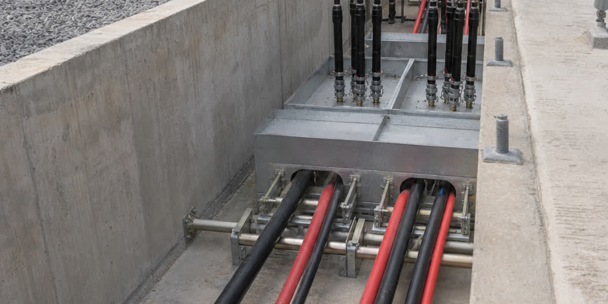
Before deploying heavy cable pulling winches into underground cable distribution networks, civil contractors must perform rigorous mechanical calculations to prevent catastrophic stretching, necking, or sidewall crushing.
                              Tension (T) --->
  ==================\==============================\==================
                     \                              \
                      \  R (Bending Radius)          \  Cable in Duct
                       \                              \
                        ===============================\==============
                                     |
                                     V
                        Sidewall Bearing Pressure (SWBP)
2.1 Maximum Permissible Pulling Tension ($T_{max}$)
The maximum pulling tension depends strictly on the attachment method:
A. Pulling via Conductor Pulling Eye (Standard Heavy Pulls)
When pulling tension is transmitted directly to the phase conductors using a bolted or soldered pulling eye:
$$T_{max} = \sigma_{max} \times n \times A$$
Where: - $\sigma_{max}$ = Maximum permissible conductor pulling stress: - Copper (Soft Annealed): $70\text{ N/mm}^2$ ($7.0\text{ kg/mm}^2$ or $10,000\text{ psi}$) - Aluminum (EC-1350 / 8000 Series): $50\text{ N/mm}^2$ ($5.0\text{ kg/mm}^2$ or $7,000\text{ psi}$) - $n$ = Number of phase conductors being pulled simultaneously - $A$ = Cross-sectional area of each conductor ($\text{mm}^2$)
Example: For a 3-core $3 \times 240\text{ mm}^2$ Copper MV cable pulled by the conductors: $$T_{max} = 70\text{ N/mm}^2 \times 3 \times 240\text{ mm}^2 = 50,400\text{ N} \approx 50.4\text{ kN} \ (\approx 5,140\text{ kgf})$$
B. Pulling via Cable Pulling Grip / Stocking (Cable Sock over Outer Sheath)
When pulling via a woven wire stocking over the outer sheath (unarmoured or non-lead cables), pulling force is limited to prevent jacket shear and insulation elongation: - Maximum Pulling Force with Stocking: $T_{grip} \le 5.0\text{ N/mm}^2 \times \text{Overall Outer Sheath Cross-Section Area}$, with an absolute ceiling of $10\text{ kN}$ to $15\text{ kN}$ regardless of cable diameter.
2.2 Sidewall Bearing Pressure ($SWBP$)
Sidewall bearing pressure represents the radial crushing force exerted on the cable insulation and metallic screen as the cable is pulled around a horizontal or vertical conduit bend. Exceeding SWBP limits causes permanent ovalization and internal dielectric void formation.
$$SWBP = \frac{T}{R}$$
Where: - $SWBP$ = Sidewall bearing pressure ($\text{N/m}$ or $\text{kN/m}$) - $T$ = Tension in the cable exiting the bend ($\text{N}$ or $\text{kN}$) - $R$ = Inside radius of the conduit bend or bend roller array ($\text{m}$)
Maximum Permissible SWBP Thresholds (IEEE / ICEA Standards)
| Cable Construction Type | Max Permissible SWBP ($\text{kN/m}$) | Max Permissible SWBP ($\text{lbs/ft}$) |
|---|---|---|
| Single-core Unarmoured XLPE / EPR | $4.4\text{ kN/m}$ | $300\text{ lbs/ft}$ |
| Three-core Unarmoured XLPE with Copper Tape | $7.3\text{ kN/m}$ | $500\text{ lbs/ft}$ |
| Three-core Armoured XLPE (SWA / STA) | $10.0\text{ kN/m}$ | $700\text{ lbs/ft}$ |
| Heavy Lead-Sheathed / Interlocked Armoured | $14.6\text{ kN/m}$ | $1,000\text{ lbs/ft}$ |
2.3 Minimum Bending Radius ($R_{min}$)
Under no circumstances should an MV cable be bent tighter than the limits defined in IEC 60502-2 and ICEA S-94-649:
| Cable Configuration | Minimum Bending Radius (During Pulling / Dynamic) | Minimum Bending Radius (Installed / Fixed Position) |
|---|---|---|
| Single-Core Unarmoured (Non-Metallic) | $20 \times D_o$ | $15 \times D_o$ |
| Single-Core Armoured (AWA / Aluminium Wire) | $18 \times D_o$ | $12 \times D_o$ |
| Three-Core Unarmoured (Copper Tape / Wire Screen) | $18 \times D_o$ | $12 \times D_o$ |
| Three-Core Armoured (SWA / STA) | $15 \times D_o$ | $12 \times D_o$ |
| At Terminations & Splice Transition Points | $15 \times D_o$ | $10 \times D_o$ (Behind Stress Cone) |
(Where $D_o$ is the overall outer diameter of the completed cable).
3. Civil Trenching, Conduit Routing & Pulling Execution
                     Direct Burial Trench Profile (MV 11kV-33kV)

       +0.00m (Grade) --------------------------------------------
                      |  Native Soil / Pavement Restoration     |
       -0.30m         |-----------------------------------------|
                      |  [ WARNING TAPE: "CAUTION BURIED HV" ]  |
       -0.60m         |-----------------------------------------|
                      |  Concrete Cable Protection Tiles        |
       -0.80m         |=========================================|
                      |  Stone-Free Sand Bedding (100mm)        |
       -0.90m         |   ( O )  ( O )  ( O )   <-- MV Cables   |
                      |  Stone-Free Sand Bedding (100mm)        |
       -1.10m         +-----------------------------------------+
                      |  Undisturbed Compacted Trench Base      |
3.1 Civil Trench Specification
- Depth: Minimum depth of cover is $0.9\text{ m}$ for $6\text{kV} - 22\text{kV}$ lines and $1.1\text{ m} - 1.2\text{ m}$ for $33\text{kV} - 35\text{kV}$ circuits under roadways.
- Bedding: Minimum $100\text{ mm}$ of washed, stone-free thermal sand ($R_{th} \le 1.2\text{ K}\cdot\text{m/W}$) below and $100\text{ mm}$ above the cables.
- Mechanical Shielding: High-impact polymer or precast concrete cable cover tiles placed $150\text{ mm}$ above the sand layer.
- Warning Marker Tape: Detectable yellow/red warning tape containing a continuous stainless steel tracer wire buried $300\text{ mm}$ below finished grade.
3.2 Pulling Equipment & Friction Reduction
- Cable Rollers: Straight line rollers placed every $2.0\text{ m} - 2.5\text{ m}$ to ensure the cable jacket never touches the trench floor or abrasive duct entry. Corner rollers must form a smooth radius exceeding $R_{min}$.
- Pulling Lubricant: High-performance water-based polymer lubricant (wax or silicone-free) compatible with HDPE/PVC jackets. Reduces coefficient of dynamic friction ($\mu$) from $0.5$ (dry concrete) down to $0.12 - 0.18$.
- Winch with Calibrated Dynamometer: Winch must be equipped with an automatic load limiter and digital tension chart recorder to guarantee pulling force never exceeds calculated $T_{max}$ and $SWBP$.
4. Precision Semi-Conductive Screen Stripping & Insulation Prep
Over 70% of medium voltage field failures occur within the first 100 mm of the cable termination or splice joint. The root cause is almost invariably improper semi-con stripping.
                           Semi-Con Stripping Geometry

    Outer Sheath    Copper Screen    Semi-Con Screen       Bare XLPE        Conductor
   +--------------+----------------+----------------+--------------------+-----------+
   |              |   (Grounded)   |  (Stress Area) |   Glass-Smooth     | (Crimped) |
   |              |  ///////////////|================|   No Scratches     |           |
   +--------------+----------------+----------------+--------------------+-----------+
   |<-- Cutback ->|<-- Overlap --->|<-- Step Dist ->|<-- Exposed Length->|<- Lug L ->|
Critical Field Workmanship Rules:
- Never Ring-Cut with a Standard Utility Knife: Utility knives penetrate through the semi-con into the underlying XLPE. A score depth of only $0.05\text{ mm}$ on the XLPE surface concentrates electric field stress to $>15\text{ kV/mm}$, initiating rapid electrical treeing breakdown.
- Use Dedicated Stripping Tools: Utilize a calibrated rotary peeling tool with an adjustable micro-depth blade for bonded semi-con, or a circumferential scoring tool for easy-strip screens.
- Chamfer the Semi-Con Transition Edge: The step between the semi-con layer and the bare XLPE must be beveled at an angle of $\le 30^\circ$ and polished to eliminate sharp micro-edges.
- Insulation Surface Abrasive Polishing: Polish the exposed XLPE insulation using non-conductive, aluminum-oxide sandpaper (grit sequence: 240 $\rightarrow$ 320 $\rightarrow$ 400 $\rightarrow$ 600). Wipe clean strictly with specialized electrical solvent wipes.
- Solvent Cleaning Protocol: Always wipe from the bare XLPE insulation toward the semi-conductive screen, never in reverse, to prevent dragging microscopic conductive carbon particles onto the insulating surface.
5. Termination & Splice/Joint Assembly: Cold-Shrink vs Heat-Shrink
Medium voltage cable terminations must satisfy IEEE Standard 48 (Class 1) and IEC 60502-4 requirements: providing dielectric insulation, environmental sealing, mechanical connection, and radial electrical stress control.
       Cold-Shrink Class 1 Outdoor Termination Architecture (11kV-35kV)

              [ Moisture Seal & Lug Pad ]
                         |
                 +-------v-------+
                 | Rain Shed #3  |  <-- Silicone Rubber Housing
                 +---------------+      (High Tracking Resistance)
                 | Rain Shed #2  |
                 +---------------+
                 | Rain Shed #1  |
                 +---------------+
                 | High-K Stress |  <-- Integrated Geometric / Hi-K
                 | Control Core  |      Refractive Stress Tube
                 +---------------+
                 | Semi-Con Step |  <-- 0-Potential Equipotential Line
                 +---------------+
                 | Ground Braid  |  <-- Constant Force Spring Bond
                 |  Earth Lead   |
                 +---------------+
5.1 Stress Control Mechanism
When the metallic screen and semi-con layer are cut back, the electric field lines diverge abruptly at the step, creating massive tangential dielectric stress ($E_t$) in the surrounding air. Two stress control technologies exist: - Geometric Stress Cone: Gradually increases the distance between the conductor and the outer ground electrode using a pre-molded conical profile, reducing electric flux density. - Refractive (High Dielectric Constant / High-K) Mastic: Utilizes a specialized semi-conductive layer with a relative permittivity $\varepsilon_r \ge 15 - 30$ to refract and smooth the electric potential distribution along the insulation interface.
5.2 Technology Comparison: Cold-Shrink vs Heat-Shrink
| Engineering Metric | Cold-Shrink Terminations (Silicone / EPDM) | Heat-Shrink Terminations (Cross-Linked Polyolefin) |
|---|---|---|
| Installation Method | Pull-out inner spiral core; instant uniform radial recovery | Requires open-flame propane gas torch |
| Thermal Expansion Memory | Continuous active radial pressure (breathes with cable thermal cycles) | Static memory; risk of void opening during severe load cycling |
| Operator Dependency | Extremely low (factory-molded geometry) | High (requires uniform heating to avoid scorch marks or trapped air) |
| Tracking Resistance | Excellent (Hydrophobic silicone rubber sheds salt & moisture) | Good (requires specialized non-tracking outer tubes) |
| Recommended Application | Switchgear compartments, outdoor pole-tops, wind turbines, substations | Standard industrial distribution, indoor dry cable vaults |
5.3 Conductor Terminals & Mechanical Clamping
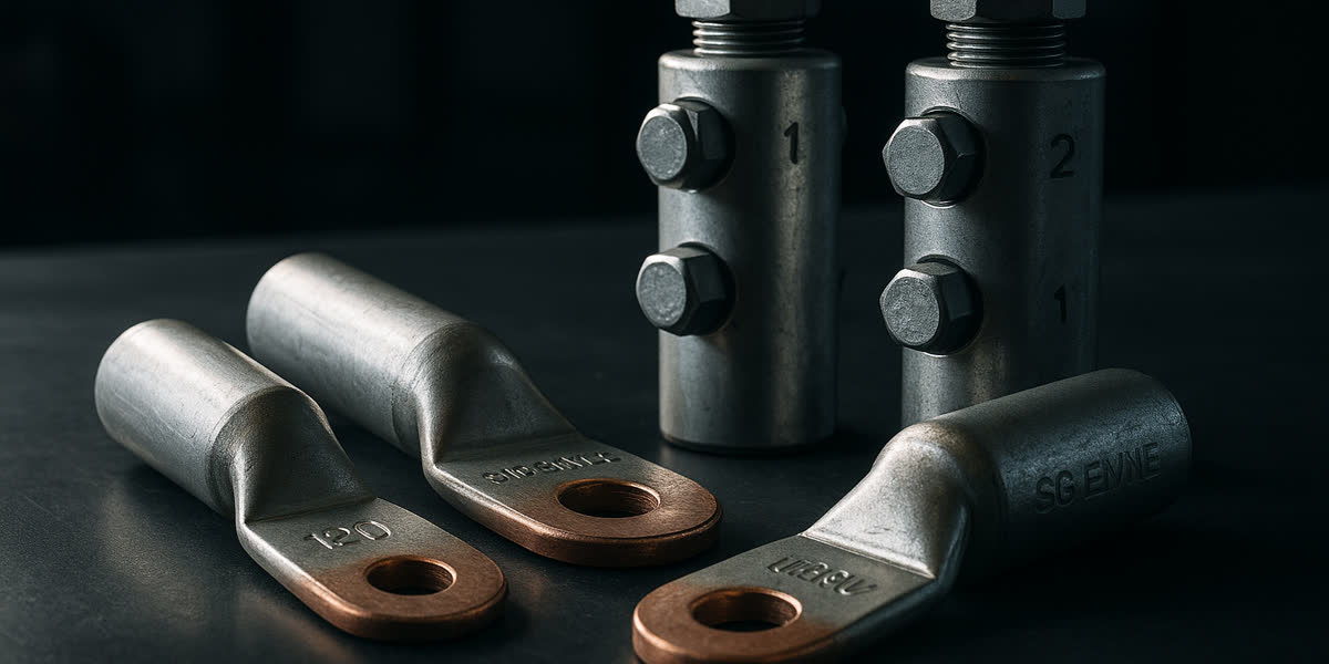
- Use bi-metallic shear-bolt mechanical connectors or heavy-duty hexagonal compression cable lugs rated for high fault currents.
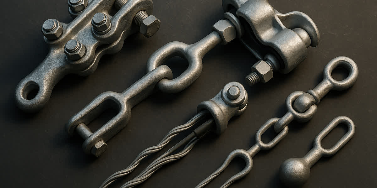
- Support outgoing cables using non-magnetic, fiberglass-reinforced or stainless steel power cable fittings and hardware (such as trefoil cable cleats) to withstand electromagnetic repulsion forces during short circuits ($F = 0.2 \cdot I_{sc}^2 / S$).
6. Single-Core Screen Grounding & Circulating Current Management
For three-core cables, the magnetic fields of the three balanced phases cancel out, resulting in near-zero induced screen voltage. However, for single-core MV cables carrying heavy currents ($>400\text{ A}$), electromagnetic induction creates substantial longitudinal sheath voltages ($V_s$).
                    Single-Core MV Cable Screen Grounding Arrangements

  A. Solid Bonding (Both Ends Grounded)
     [G] ======================================================== [G]
     * Advantage: Zero sheath voltage standing potential.
     * Disadvantage: High circulating sheath eddy currents (reduces cable ampacity by 15-35%).

  B. Single-Point Bonding (One End Grounded, One End with SVL)
     [G] ======================================================== [SVL] --> [G]
     * Advantage: Zero circulating current; allows 100% full conductor ampacity.
     * Requirement: Sheath standing voltage at open end must remain < 65V under continuous full load.

  C. Cross-Bonding (Sectional Transposition for Long Substation Runs)
     Major Section 1         Major Section 2         Major Section 3
     Phase A ---\ /---------- Phase B ---\ /---------- Phase C -----------
                 X                        X
     Phase B ---/ \---------- Phase C ---/ \---------- Phase A -----------
     * Advantage: Sheath induced voltages sum to zero vectorially at each major section junction.
7. Commissioning, Acceptance & Field Diagnostic Testing
Prior to energization, the cable system must undergo structured commissioning verification in strict compliance with IEEE 400.2-2013, IEC 60502-2, and ICEA S-94-649.
+---------------------------------------------------------------------------------------+
|                 Comprehensive MV Cable Commissioning & Testing Sequence               |
|                                                                                       |
|  [ Step 1: Pre-Test Visual Inspection & Phase Verification ]                          |
|         |                                                                             |
|  [ Step 2: DC Outer Sheath Integrity Test (IEC 60229: 5kV-10kV DC for 1 min) ]        |
|         |                                                                             |
|  [ Step 3: Insulation Resistance (IR) Megger Test (2.5kV / 5kV DC, 1 min & 10 min) ]  |
|         |                                                                             |
|  [ Step 4: VLF 0.1Hz AC Withstand / Hi-Pot Test (IEEE 400.2: 2.0 to 3.0 U0, 15-60min) ]|
|         |                                                                             |
|  [ Step 5: Advanced Diagnostics: VLF Tan Delta (TD) & Monitored Partial Discharge ]   |
|         |                                                                             |
|  [ Step 6: Final Discharge, Grounding & System Energization ]                         |
+---------------------------------------------------------------------------------------+
7.1 Outer Sheath DC Voltage Test (IEC 60229)
- Objective: Verify that the outer HDPE/PVC jacket suffered no punctures, abrasions, or rock penetration during pulling.
- Method: Apply $5\text{ kV} - 10\text{ kV DC}$ between the metallic screen/armor and earth for 1 minute.
- Acceptance Criteria: Leakage current must remain stable with zero breakdown; insulation resistance $>10\text{ M}\Omega\cdot\text{km}$.
7.2 Why Traditional DC Hi-Pot Testing is Prohibited on XLPE Cables
Historically, high-voltage DC withstand testing was standard for paper-insulated lead-covered (PILC) cables. On modern XLPE cables, DC testing is strictly prohibited by IEEE 400 and CIGRE: 1. DC fields cause massive accumulations of space charges around microscopic water trees and dielectric discontinuities. 2. When the cable is grounded or re-energized with AC voltage, the trapped space charges create localized electric stress enhancements exceeding the dielectric breakdown strength of XLPE, precipitating catastrophic premature failure.
7.3 VLF (Very Low Frequency, 0.1 Hz) AC Withstand Testing
VLF (0.1 Hz sinusoidal or cosine-rectangular) AC testing is the universally mandated standard per IEEE 400.2:
IEEE 400.2 VLF Test Voltages for MV Cable Systems (Installation & Acceptance)
| System Rated Voltage ($U_0 / U$) | Maximum System Voltage ($U_m$) | Installation Test Voltage (RMS at 0.1 Hz) | Acceptance Test Voltage (RMS at 0.1 Hz) | Test Duration |
|---|---|---|---|---|
| 3.6 / 6 kV | $7.2\text{ kV}$ | $11\text{ kV}$ ($3.0 U_0$) | $13\text{ kV}$ ($3.5 U_0$) | $15 - 60\text{ min}$ |
| 6 / 10 kV (8.7/10 kV) | $12\text{ kV}$ | $18\text{ kV}$ ($3.0 U_0$) | $21\text{ kV}$ ($3.5 U_0$) | $15 - 60\text{ min}$ |
| 8.7 / 15 kV | $17.5\text{ kV}$ | $26\text{ kV}$ ($3.0 U_0$) | $30\text{ kV}$ ($3.5 U_0$) | $15 - 60\text{ min}$ |
| 12 / 20 kV (12.7/22 kV) | $24\text{ kV}$ | $36\text{ kV}$ ($2.8 U_0$) | $42\text{ kV}$ ($3.3 U_0$) | $15 - 60\text{ min}$ |
| 18 / 30 kV (19/33 kV) | $36\text{ kV}$ | $54\text{ kV}$ ($2.8 U_0$) | $63\text{ kV}$ ($3.3 U_0$) | $15 - 60\text{ min}$ |
| 20.8 / 35 kV (26/35 kV) | $40.5\text{ kV}$ | $60\text{ kV}$ ($2.3 U_0$) | $70\text{ kV}$ ($2.7 U_0$) | $15 - 60\text{ min}$ |
7.4 Tan Delta ($\tan \delta$) and Monitored Partial Discharge (PD) Criteria
- Tan Delta ($\tan \delta$): Measures overall dielectric dissipation factor. An aging or moisture-degraded XLPE insulation exhibits an elevated mean $\tan \delta$ ($>1.2 \times 10^{-3}$) and significant differential $\Delta\tan \delta$ between $0.5 U_0$ and $1.5 U_0$.
- Partial Discharge (PD) Testing: Pinpoints localized void discharge inside terminations and joints. Acceptance criterion: $\text{PD magnitude} < 5\text{ pC}$ at $1.73 U_0$ per IEC 60502-2.
8. Technical Parameters & Standards Matrix for 6kV–35kV Cables
The following engineering table outlines the standard structural and electrical specifications of SiTong Cable's medium voltage power cables complying with IEC 60502-2 / BS 6622 / ICEA S-94-649:
| Nominal Voltage Rating ($U_0/U$) | Nominal Insulation Thickness (mm) | Conductor Cross-Section Range ($\text{mm}^2$) | Metallic Screen Short-Circuit Current ($1\text{s}, \text{kA}$) | Minimum AC Withstand Voltage ($5\text{ min, 50Hz}$) | Maximum DC Conductor Resistance at 20°C (Cu $240\text{mm}^2$, $\Omega/\text{km}$) |
|---|---|---|---|---|---|
| 3.6 / 6 kV (7.2 kV) | $2.5\text{ mm}$ | $25 - 630\text{ mm}^2$ | $3.5 - 7.5\text{ kA}$ | $12.5\text{ kV}$ | $0.0754\ \Omega/\text{km}$ |
| 6 / 10 kV (12 kV) | $3.4\text{ mm}$ | $25 - 630\text{ mm}^2$ | $3.5 - 7.5\text{ kA}$ | $21.0\text{ kV}$ | $0.0754\ \Omega/\text{km}$ |
| 8.7 / 15 kV (17.5 kV) | $4.5\text{ mm}$ | $35 - 630\text{ mm}^2$ | $4.2 - 9.0\text{ kA}$ | $30.5\text{ kV}$ | $0.0754\ \Omega/\text{km}$ |
| 12 / 20 kV (24 kV) | $5.5\text{ mm}$ | $50 - 630\text{ mm}^2$ | $4.2 - 9.0\text{ kA}$ | $42.0\text{ kV}$ | $0.0754\ \Omega/\text{km}$ |
| 18 / 30 kV (36 kV) | $8.0\text{ mm}$ | $70 - 630\text{ mm}^2$ | $5.5 - 12.0\text{ kA}$ | $63.0\text{ kV}$ | $0.0754\ \Omega/\text{km}$ |
| 26 / 35 kV (40.5 kV) | $9.0 - 10.5\text{ mm}$ | $95 - 630\text{ mm}^2$ | $5.5 - 14.0\text{ kA}$ | $91.0\text{ kV}$ | $0.0754\ \Omega/\text{km}$ |
9. SiTong Cable Quality Assurance & Manufacturing Excellence
As an internationally certified cable manufacturer, Zhengzhou SiTong Cable Co., Ltd. (SiTong Cable) operates world-class triple-extrusion (3-in-1 CCV) dry gas vulcanization lines dedicated to producing premium medium voltage power cables up to 35kV.
Why Global Utilities and EPC Contractors Choose SiTong MV Cables:
- Triple-Tandem CCV Extrusion: The conductor screen, super-clean XLPE insulation, and insulation screen are extruded simultaneously in a single pressurized curing tube, eliminating inter-layer air gaps and microscopic contamination.
- 100% Routine Factory Testing: Every manufactured drum undergoes full-length high-voltage AC spark testing, routine dielectric withstand testing, and online partial discharge screening ($\text{PD} < 2\text{ pC}$ at $2.0 U_0$, exceeding IEC requirements).
- Rigorous Material Traceability: Sourced strictly from virgin polymer compounds (Borouge / Dow) and $99.99\%$ pure electrolytic cathode copper / EC-grade aluminum.
- International Accreditation: Certified to ISO 9001, ISO 14001, ISO 45001, CE, and third-party type test certifications matching IEC 60502-2, BS 6622, AS/NZS 1429.1, and ICEA S-94-649.
10. Frequently Asked Questions (FAQ)
Q1: Can I use DC high-voltage testing to commission newly installed MV XLPE cables?
No. Both IEEE 400 and IEC standards strictly prohibit high-voltage DC withstand testing on XLPE insulated cables. DC testing induces dangerous trapped space charge configurations within the polymer matrix. When the cable is restored to AC operation, these space charges exacerbate localized electrical fields, initiating micro-void partial discharge and causing premature dielectric puncture. Always use VLF (0.1 Hz) AC withstand testing per IEEE 400.2.
Q2: What is the single most common cause of medium voltage cable joint and termination failure?
The leading cause (accounting for $>70\%$ of accessory breakdowns) is knife scoring on the primary XLPE insulation during semi-conductive screen removal. Even a minor axial scratch or circumferential groove creates a severe electric field concentration point. Always use dedicated, depth-controlled peeling tools and polish the exposed insulation with fine aluminum-oxide abrasive paper down to a mirror finish.
Q3: Why is single-point bonding used on long single-core MV cable runs instead of solid grounding at both ends?
Solidly grounding both ends of single-core cable metallic sheaths creates a closed loop with the earth. The alternating magnetic field of the phase conductor induces heavy circulating currents in the sheath, causing severe $I^2R$ thermal losses that can derate the cable's current-carrying capacity by $15\% - 35\%$. Single-point bonding eliminates circulating currents entirely, provided that sheath voltage limiters (SVLs) are installed at the ungrounded end to clamp transient overvoltages below touch-safe limits ($<65\text{ V}$).
Q4: How do I determine whether to specify SWA (Steel Wire Armour) or STA (Steel Tape Armour) for medium voltage cables?
Specify Steel Wire Armour (SWA) when the cable will be subjected to significant longitudinal tensile pull, vertical shaft suspension, or horizontal directional drilling (HDD). SWA provides superior tensile strength. Specify Steel Tape Armour (STA) for standard underground direct burial trenches where the primary mechanical risk is static radial compression, backfill stone crushing, or accidental excavator bucket glancing. Note: For single-core AC cables, non-magnetic Aluminum Wire Armour (AWA) must always be used instead of magnetic steel to prevent magnetic hysteresis overheating.
11. Engineering Support & Project Inquiries
Executing a reliable medium voltage cable installation requires precision engineering, robust products, and rigorous testing protocols. SiTong Cable provides turnkey technical support, cable sizing calculations, and certified medium voltage power cables for substation, utility, and renewable energy infrastructure worldwide.
👉 Browse our Medium Voltage Power Cable Range
👉 Medium Voltage Power Cable (MV): Complete Technical Specifications and Selection Guide
👉 Contact SiTong Engineering Team for MV Cable Projects
📬 Sales inquiries: sales@sitongcable.com | 📞 Phone: +86-371-69176007