Aluminum Overhead Service Drop Cable (Duplex, Triplex, Quadruplex): Complete Technical Specification, Sizing & Selection Guide
Aluminum Overhead Service Drop Cable (Duplex, Triplex, Quadruplex): Complete Technical Specification, Sizing & Selection Guide
Comprehensive engineering guide to aluminum overhead service drop cables (Duplex, Triplex, Quadruplex) per ANSI/ICEA S-76-474 and ASTM B230/B231/B232/B399 standards. Learn conductor sizing, neutral messenger selection, ampacity, and installation best practices.
Overhead service drop cables are the backbone of low-voltage secondary power distribution worldwide. Serving as the vital electrical link between secondary distribution transformers mounted on utility poles and customer meter bases or weatherheads, these bundled cable assemblies deliver reliable power to residential, commercial, agricultural, and light industrial facilities.
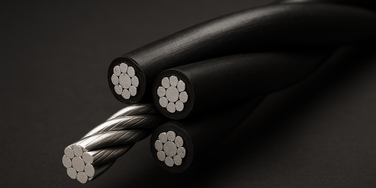
Unlike traditional open-wire bare overhead conductors, modern service drop cables utilize insulated aluminum phase conductors twisted around a bare or insulated neutral messenger. This configuration provides superior mechanical support, prevents phase-to-phase short circuits caused by wind galloping or tree contact, minimizes electrical losses, and significantly reduces installation time.
This comprehensive technical guide explores the classifications, international manufacturing standards, ASTM industry code words, neutral messenger configurations, ampacity ratings, electrical sizing calculations, and field installation practices for Duplex, Triplex, and Quadruplex aluminum service drop cables.
1. Classification & Architecture of Overhead Service Drop Cables
Overhead service drop cables, commonly grouped under aerial bundled cable (ABC) systems for low-voltage secondary networks, are categorized by the number of insulated phase conductors twisted around a central neutral supporting messenger.
       [ Overhead Service Drop Cable Architecture ]

   DUPLEX (1 Phase + 1 Neutral)       ---> 120V Single-Phase / Street Lighting
   TRIPLEX (2 Phases + 1 Neutral)     ---> 120/240V 3-Wire Single-Phase Residential
   QUADRUPLEX (3 Phases + 1 Neutral)  ---> 120/208V or 277/480V 3-Phase Commercial
A. Duplex Service Drop
- Configuration: One insulated phase conductor twisted around one bare or covered neutral messenger conductor.
- Voltage Rating: 600 V phase-to-phase / phase-to-ground (operating typically at 120 V single-phase).
- Primary Applications: Single-phase 120 V secondary connections, rural street lighting circuits, highway illumination feeds, security lighting, and temporary construction power feeds.
B. Triplex Service Drop
- Configuration: Two insulated phase conductors twisted around one bare or covered neutral messenger conductor.
- Voltage Rating: 600 V rated (operating at 120/240 V single-phase, 3-wire system).
- Primary Applications: Standard residential service drops from overhead pole-mounted distribution transformers to residential weatherheads and meter bases; agricultural pump feeds; small commercial single-phase loads.
C. Quadruplex Service Drop
- Configuration: Three insulated phase conductors twisted around one bare or covered neutral messenger conductor.
- Voltage Rating: 600 V rated (operating at 120/208 V 4-wire wye or 277/480 V 4-wire wye three-phase systems, or 240 V delta systems).
- Primary Applications: Commercial establishments, small manufacturing facilities, commercial strip malls, three-phase agricultural irrigation systems, schools, and institutional facilities requiring three-phase overhead power delivery.
2. Applicable Manufacturing Standards & Material Specifications
High-reliability overhead service drop cables must comply with rigorous North American and international electromechanical standards:
| Standard Reference | Scope & Governing Technical Requirement |
|---|---|
| ANSI / ICEA S-76-474 | Standard for Neutral-Supported Power Cable Assemblies with Weather-Resistant Extruded Insulation Rated 600 Volts |
| ASTM B230 / B230M | Standard Specification for Aluminum 1350-H19 Wire for Electrical Purposes (Hard-Drawn Aluminum) |
| ASTM B231 / B231M | Standard Specification for Concentric-Lay-Stranded Aluminum 1350 Conductors (AAC Conductor) |
| ASTM B232 / B232M | Standard Specification for Concentric-Lay-Stranded Aluminum Conductors, Coated-Steel Reinforced (ACSR Conductor) |
| ASTM B399 / B399M | Standard Specification for Concentric-Lay-Stranded Aluminum-Alloy 6201-T81 Conductors (AAAC Conductor) |
| ASTM B901 | Standard Specification for Compressed Round Stranded Aluminum Conductors Using Single Input Wire Construction |
| UL 854 | Standard for Service-Entrance Cables (governing safety and insulation requirements for service equipment interface) |
| NF C 33-209 | French standard for low-voltage aerial bundled cables (used extensively across Africa, Latin America, and Middle East) |
Conductor & Insulation Materials
- Phase Conductors: Concentric-lay-stranded or compressed 1350-H19 hard-drawn aluminum wire (minimum conductivity 61.2% IACS).
- Insulation Systems:
- Cross-Linked Polyethylene (XLPE): Rated for 90°C continuous operating temperature, 130°C emergency overload, and 250°C short-circuit conditions. Offers superior resistance to UV radiation, environmental stress cracking, ozone, and thermal aging.
- High-Density Polyethylene (HDPE): Rated for 75°C continuous operating temperature. Delivers excellent abrasion resistance and weatherability at economical cost.
- Neutral Supporting Messenger:
- ACSR (Aluminum Conductor Steel Reinforced): High-tensile steel core stranded with 1350-H19 aluminum wires for long-span and high-mechanical-load applications.
- AAAC (6201-T81 Aluminum Alloy): High-strength heat-treated aluminum-magnesium-silicon alloy providing high strength-to-weight ratio and outstanding atmospheric corrosion resistance.
- AAC (1350-H19 Aluminum): Full-aluminum construction used for short urban spans where mechanical loading is minimal.
3. Technical Specifications & Industry ASTM Code Words
In utility procurement and international electrical engineering, aluminum overhead service drop cables are universally specified by standardized ASTM animal, bird, and geographical code words. The following reference tables detail the mechanical and electrical parameters of standard constructions.
Table 1: Triplex Service Drop Cable Specifications (600V, XLPE Insulated, ACSR Neutral Messenger)
| ASTM Code Word | Phase Conductor Size (AWG) | Phase Stranding (No. x mm) | Insulation Thickness (mm / mils) | ACSR Messenger Size (AWG) | Messenger Stranding (Al/St) | Approx. Cable Weight (kg/km) | Rated Breaking Strength (kN) | Ampacity @ 90°C XLPE (Amps)* |
|---|---|---|---|---|---|---|---|---|
| Volida | 6 (13.3 mm²) | 7 x 1.55 | 1.14 / 45 | 6 | 6/1 | 148 | 5.30 | 100 |
| Cinder | 4 (21.2 mm²) | 7 x 1.96 | 1.14 / 45 | 4 | 6/1 | 215 | 8.27 | 135 |
| Terrier | 4 (21.2 mm²) | 7 x 1.96 | 1.14 / 45 | 2 | 6/1 | 258 | 12.68 | 135 |
| Perch | 2 (33.6 mm²) | 7 x 2.47 | 1.14 / 45 | 2 | 6/1 | 325 | 12.68 | 180 |
| Colleen | 1/0 (53.5 mm²) | 7 x 3.12 | 1.52 / 60 | 1/0 | 6/1 | 512 | 19.48 | 235 |
| Conch | 2/0 (67.4 mm²) | 7 x 3.50 | 1.52 / 60 | 2/0 | 6/1 | 628 | 23.80 | 270 |
| Neritina | 3/0 (85.0 mm²) | 7 x 3.93 | 1.52 / 60 | 3/0 | 6/1 | 772 | 29.60 | 315 |
| Cerapus | 4/0 (107.2 mm²) | 7 x 4.42 | 1.52 / 60 | 4/0 | 6/1 | 950 | 37.10 | 360 |
*Ampacity calculated per IEEE standard conditions: Ambient temperature 40°C, conductor temperature 90°C, wind velocity 0.61 m/s (2 ft/s), solar radiation 1000 W/m².
Table 2: Quadruplex Service Drop Cable Specifications (600V, XLPE Insulated, ACSR Neutral Messenger)
| ASTM Code Word | Phase Conductor Size (AWG) | Phase Stranding (No. x mm) | Insulation Thickness (mm / mils) | ACSR Messenger Size (AWG) | Messenger Stranding (Al/St) | Approx. Cable Weight (kg/km) | Rated Breaking Strength (kN) | Ampacity @ 90°C XLPE (Amps)* |
|---|---|---|---|---|---|---|---|---|
| Tulsa | 6 (13.3 mm²) | 7 x 1.55 | 1.14 / 45 | 6 | 6/1 | 198 | 5.30 | 90 |
| Sofia | 4 (21.2 mm²) | 7 x 1.96 | 1.14 / 45 | 4 | 6/1 | 290 | 8.27 | 120 |
| Miami | 2 (33.6 mm²) | 7 x 2.47 | 1.14 / 45 | 2 | 6/1 | 442 | 12.68 | 160 |
| Dallas | 1/0 (53.5 mm²) | 7 x 3.12 | 1.52 / 60 | 1/0 | 6/1 | 698 | 19.48 | 210 |
| Austin | 2/0 (67.4 mm²) | 7 x 3.50 | 1.52 / 60 | 2/0 | 6/1 | 858 | 23.80 | 240 |
| Lima | 3/0 (85.0 mm²) | 7 x 3.93 | 1.52 / 60 | 3/0 | 6/1 | 1055 | 29.60 | 280 |
| Munich | 4/0 (107.2 mm²) | 7 x 4.42 | 1.52 / 60 | 4/0 | 6/1 | 1300 | 37.10 | 315 |
Table 3: Duplex Service Drop Cable Specifications (600V, XLPE Insulated, ACSR Neutral Messenger)
| ASTM Code Word | Phase Conductor Size (AWG) | Phase Stranding (No. x mm) | Insulation Thickness (mm / mils) | ACSR Messenger Size (AWG) | Approx. Cable Weight (kg/km) | Rated Breaking Strength (kN) | Ampacity @ 90°C XLPE (Amps)* |
|---|---|---|---|---|---|---|---|
| Peking | 6 (13.3 mm²) | 7 x 1.55 | 1.14 / 45 | 6 (6/1) | 98 | 5.30 | 100 |
| Collie | 4 (21.2 mm²) | 7 x 1.96 | 1.14 / 45 | 4 (6/1) | 142 | 8.27 | 135 |
| Terrier | 2 (33.6 mm²) | 7 x 2.47 | 1.14 / 45 | 2 (6/1) | 215 | 12.68 | 180 |
| Spaniel | 1/0 (53.5 mm²) | 7 x 3.12 | 1.52 / 60 | 1/0 (6/1) | 338 | 19.48 | 235 |
| Setter | 2/0 (67.4 mm²) | 7 x 3.50 | 1.52 / 60 | 2/0 (6/1) | 415 | 23.80 | 270 |
4. Neutral Supporting Messenger Engineering: ACSR vs AAAC vs AAC
The neutral conductor in an overhead service drop assembly serves two simultaneous critical functions: it carries the unbalanced electrical return current (and fault return path) and acts as the sole structural load-bearing member supporting the mechanical tension and weight of the entire cable bundle.
+-----------------------------------------------------------------------------+
|                      NEUTRAL MESSENGER SELECTION MATRIX                     |
+-------------------+----------------------+----------------------------------+
| Messenger Type    | Mechanical Strength  | Recommended Operational Scenario |
+-------------------+----------------------+----------------------------------+
| ACSR (ASTM B232)  | ★★★★★ (Highest)      | Long spans (>40m), High wind/ice |
| AAAC (ASTM B399)  | ★★★★☆ (High)         | Coastal, Marine, Chemical zones  |
| AAC (ASTM B231)   | ★★☆☆☆ (Moderate)     | Short urban spans (<25m), Benign |
| Insulated Neutral | Dependent on core    | Corrosive, High vegetation, Theft|
+-------------------+----------------------+----------------------------------+
- Bare ACSR Conductor Messenger:
- Features a galvanized or aluminum-clad steel core (ASTM B498/ASTM B502).
- Provides the highest ultimate tensile strength (UTS) per cross-sectional area.
- Essential in regions subject to National Electrical Safety Code (NESC) Heavy Loading (freezing ice accumulation + high transverse wind).
-
Allows pole-to-building spans exceeding 45–60 meters without exceeding allowable sag limits.
-
Bare AAAC Conductor (6201-T81) Messenger:
- Homogeneous aluminum-alloy construction with no dissimilar metal interface.
- Eliminates the risk of galvanic corrosion between aluminum and zinc/steel, making it the premier choice for coastal, tropical, and heavily polluted industrial environments.
-
Delivers approximately 90% of the mechanical strength of equivalent ACSR with superior electrical conductivity and lower overall weight.
-
Bare AAC Conductor (1350-H19) Messenger:
- Full hard-drawn aluminum wire.
-
Lowest tensile strength; strictly limited to short drop spans (typically under 20–25 meters) in mild climates with zero ice loading.
-
Covered / Insulated Neutral Messenger:
- Encased in black weather-resistant XLPE or HDPE matching the phase conductors.
- Prevents corrosion in chemical environments, protects against inadvertent contact with low-hanging telecom cables, and prevents illegal direct neutral tapping.
5. Electrical Sizing Methodology: Ampacity & Voltage Drop
Proper sizing of overhead service drop cables requires verifying both continuous thermal ampacity and permissible steady-state voltage drop under peak design loads.
A. Continuous Thermal Current Sizing
The operating current ($I_{load}$) must not exceed the cable ampacity ($I_z$) after applying ambient temperature correction factors ($K_{temp}$):
$$I_z = I_{catalog} \times K_{temp}$$
Where ambient temperature derating factors for 90°C XLPE insulation are: - $30^\circ\text{C}$: $1.09$ - $40^\circ\text{C}$: $1.00$ (Standard design baseline) - $45^\circ\text{C}$: $0.95$ - $50^\circ\text{C}$: $0.89$
B. Voltage Drop Calculation
In secondary distribution, utility standards generally mandate that service drop voltage drop must not exceed 2.0% to 3.0% between the transformer secondary terminals and the customer meter.
For single-phase 120/240V Triplex circuits: $$V_{drop} = 2 \times I \times L \times (R \cdot \cos\theta + X \cdot \sin\theta)$$
For three-phase 120/208V or 277/480V Quadruplex circuits: $$V_{drop} = \sqrt{3} \times I \times L \times (R \cdot \cos\theta + X \cdot \sin\theta)$$
Where: - $I$ = Load current (Amperes) - $L$ = One-way circuit length (km or thousands of feet) - $R$ = AC conductor resistance at 75°C/90°C ($\Omega/\text{km}$) - $X$ = Inductive reactance at 60 Hz ($\Omega/\text{km}$) (typically $0.085 - 0.105\,\Omega/\text{km}$ for bundled configurations) - $\cos\theta$ = Power factor of the load (typically $0.85 - 0.95$ lagging)
Sizing Example:
A residential service requires a 150 A continuous load fed at 240 V single-phase over a 45-meter overhead span. Power factor is 0.90 lagging. - Selecting 4/0 AWG Triplex ("Cerapus"): $R_{ac} \approx 0.334\,\Omega/\text{km}$, $X \approx 0.092\,\Omega/\text{km}$. - $V_{drop} = 2 \times 150 \times 0.045 \times (0.334 \times 0.90 + 0.092 \times 0.436) = 13.5 \times (0.3006 + 0.0401) = 4.60\,\text{V}$. - Percentage drop: $\frac{4.60\,\text{V}}{240\,\text{V}} \times 100\% = 1.92\%$ (Fully compliant with $<2.0\%$ standard).
6. Field Installation Best Practices & Hardware Guidelines
Adhering to strict mechanical and physical installation practices ensures long-term service reliability and prevents conductor fatigue or insulation damage.
       POLE ATTACHMENT                                 BUILDING WEATHERHEAD
   +---------------------+                            +---------------------+
   | Pole Bracket / Hook |                            | Service Mast Clamp  |
   | Wedge Dead-End Clamp|==== Service Drop Bundle ===| Wedge Dead-End Clamp|
   | Insulated IPC Tap   |                            | Drip Loop to Meter  |
   +---------------------+                            +---------------------+
1. NESC Ground Clearance Requirements (Rule 232)
Overhead service drop spans must maintain mandatory minimum vertical clearances above ground, roads, and structures: - Above residential driveways and commercial parking: Minimum 3.7 m (12.0 ft) to 4.6 m (15.0 ft). - Above public streets, alleys, and roads subject to truck traffic: Minimum 4.9 m (16.0 ft) to 5.5 m (18.0 ft). - Above residential spaces and pedestrian walkways: Minimum 3.0 m (10.0 ft) to 3.7 m (12.0 ft). - Clearance from building windows, doors, and fire escapes: Minimum 0.9 m (3.0 ft) radial clearance.
2. Supporting Hardware & Dead-End Clamping
- Wedge Dead-End Clamps: The neutral messenger must be gripped using bail-type wedge clamps sized specifically to the neutral conductor diameter. Never clamp or apply mechanical tension to the insulated phase conductors.
- Service Mast Attachments: Secure the building end to an engineered service mast or through-bolt building attachment bracket capable of withstanding the full dead-end tension under maximum ice and wind loading.
- Drip Loops: At the building weatherhead interface, form generous downward drip loops in the insulated phase conductors before splicing into building service entrance conductors. This prevents rainwater migration into the service conduit.
- Insulation Piercing Connectors (IPC): When tapping service drop conductors to secondary main lines, use torque-controlled shear-head IPCs to create hermetically sealed, water-tight connections without stripping insulation.
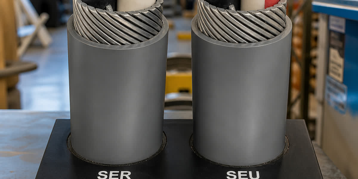
7. Overhead Service Drop vs Underground Concentric Cable
Utilities and distribution designers frequently evaluate whether to deploy overhead service drop assemblies or underground concentric cable service entrances.
| Technical Parameter | Overhead Service Drop (ABC Cable) | Underground Concentric Cable |
|---|---|---|
| Capital Installation Cost | Low to moderate (Fast pole-to-mast stringing) | Higher (Requires trenching, backfilling, ductwork) |
| Aesthetic Impact | Visible overhead wires in streetscape | Fully concealed underground |
| Weather & Storm Resilience | Susceptible to extreme wind, falling trees | Highly immune to wind, storms, ice loading |
| Anti-Theft Protection | Moderate (Tapping requires pole climbing) | High (Fully shielded neutral/ground layer) |
| Fault Location & Repair Time | Immediate visual inspection; fast repair | Requires specialized TDR fault locators |
| Typical Service Lifespan | 25 to 35 years (UV and weather exposed) | 40 to 50+ years (Protected in subsoil) |
8. Frequently Asked Questions (FAQ)
Q1: What is the main difference between Triplex and Quadruplex service drop cable?
A: Triplex cable contains two insulated phase conductors twisted around a neutral messenger and is designed for single-phase 120/240 V 3-wire electrical service (standard residential homes and small single-phase loads). Quadruplex cable contains three insulated phase conductors twisted around a neutral messenger and is engineered for 3-phase 4-wire systems (120/208 V, 240 V, or 277/480 V) commonly used in commercial, institutional, and industrial facilities.
Q2: Why is XLPE insulation preferred over HDPE/PVC for overhead service drop cables?
A: Cross-linked polyethylene (XLPE) provides a higher maximum continuous operating temperature rating (90°C vs 75°C for HDPE/PVC), allowing higher current-carrying capacity (ampacity) for the same conductor size. Furthermore, XLPE offers superior thermal overload resistance (130°C), excellent short-circuit survival (250°C), superior UV and environmental stress crack resistance, and longer operational life under harsh solar radiation.
Q3: When should an ACSR neutral messenger be selected over an AAAC messenger?
A: An ACSR neutral messenger should be selected for long spans (exceeding 35–40 meters) or geographic areas subject to high wind pressures and heavy ice accumulation (e.g., NESC Heavy loading district), where high tensile breaking strength is essential. An AAAC messenger is preferred in coastal, humid tropical, or aggressive industrial environments because its homogeneous aluminum-alloy chemistry eliminates the potential for galvanic corrosion between steel and aluminum.
Q4: Can overhead service drop cable be buried directly underground?
A: No. Standard overhead service drop cables (Duplex, Triplex, Quadruplex per ANSI/ICEA S-76-474) are engineered strictly for aerial, outdoor overhead use. They do not possess the heavy-duty water-blocking moisture barriers, robust outer jackets, or mechanical protection required for direct burial. For underground secondary service entrances, utilities must install direct-burial secondary URD cables or concentric neutral cables.
Q5: How are phase conductors identified in Triplex and Quadruplex assemblies?
A: In compliance with ANSI/ICEA S-76-474, phase conductors are identified by permanent longitudinal extruded colored stripes or surface ridges molded directly into the black XLPE insulation. Typically, one phase has a single longitudinal stripe/ridge, the second has double stripes/ridges or a red stripe, and the third phase (in Quadruplex) has triple stripes or a blue stripe, while the neutral remains bare or clearly marked with neutral identification.
Technical Summary & Sizing Recommendations
Selecting the optimal overhead service drop cable requires balancing electrical capacity, voltage drop constraints, span distance, and climatic mechanical loading. By standardizing on high-grade ASTM 1350-H19 aluminum phase conductors with 90°C UV-resistant XLPE insulation and high-strength ACSR or AAAC messengers, utilities and contractors achieve decades of reliable, low-maintenance electrical distribution.
👉 Browse our Aerial Bundled Cable & Service Drop Product Range
👉 Explore Bare Conductor ACSR / AAAC Messenger Specifications
👉 Contact our Engineering Team for Custom Quotations & Specifications
📬 Sales inquiries: sales@sitongcable.com | 📞 Phone: +86-371-69176007