Overhead Conductor Corrosion Protection in Coastal & Marine Environments: Technical Guide to ACSR, AAAC, Greased ACSR & ACAR Selection (IEC 61089, ISO 9223, EN 50182)
Overhead Conductor Corrosion Protection in Coastal & Marine Environments: Technical Guide to ACSR, AAAC, Greased ACSR & ACAR Selection (IEC 61089, ISO 9223, EN 50182)
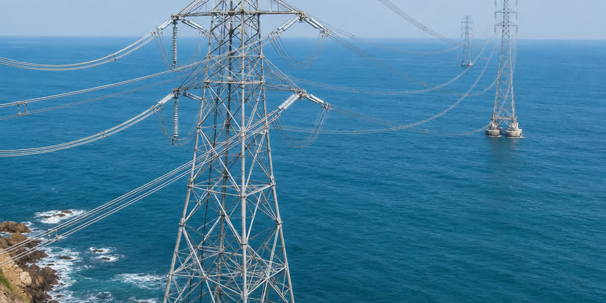
Overhead transmission lines in coastal, saline, and aggressive industrial environments face rapid structural degradation from galvanic corrosion, airborne chlorides, and moisture ingress. This comprehensive engineering guide examines corrosion mechanisms across bare overhead conductors, compares standard ACSR, greased ACSR, all-aluminum alloy (AAAC), and aluminum conductor alloy reinforced (ACAR) under ISO 9223 corrosivity classes (C1–CX), details IEC 61395 grease protection grades, and outlines hardware compatibility to maximize transmission line lifespan.
💡 Executive Engineering Decision Summary (Quick Selection Rule for Marine Lines): - ISO 9223 C1–C3 (Inland & Mild Urban / >20 km from coastline): Standard ACSR (ASTM B232 / IEC 61089) provides optimal strength-to-cost ratio with a design life of 30–50 years. - ISO 9223 C4 (Coastal Belt 3–20 km / Heavy Industrial): Homogeneous AAAC (Al-Mg-Si 6201) is recommended for standard spans (<400 m) to eliminate internal galvanic battery formation; specify IEC 61395 Case 2/3 Greased ACSR for longer spans. - ISO 9223 C5 / CX (Marine Shorelines <3 km, Offshore Island Links & Heavy Chemical): IEC 61395 Case 3/4 Total-Greased ACSR or ACAR with friction-welded bi-metallic transition hardware; standard ungreased ACSR is strictly prohibited due to internal galvanic core rot.
1. Atmospheric Corrosivity & Degradation Mechanisms in Overhead Lines
Overhead power transmission and distribution conductors operating within littoral zones, coastal corridors, and industrial chemical clusters are continuously exposed to severe environmental stressors. When relative humidity exceeds 70% and airborne salinity concentrates on conductor surfaces, atmospheric moisture creates an aggressive electrolyte film across the outer and inner strands.
The Electrochemical Kinetics of Conductor Corrosion
Conductor degradation is rarely uniform; it proceeds through several distinct electrochemical and mechanical pathways:
- Galvanic (Bimetallic) Cell Formation: In standard ACSR conductors, the core utilizes zinc-coated high-tensile steel, surrounded by hard-drawn aluminum (Al-1350) strands. In the presence of a saline electrolyte (containing dissolved Na⁺ and Cl⁻ ions), a galvanic couple is established. Pure aluminum exhibits an electrode potential of approximately -0.85 V (vs. Standard Calomel Electrode, SCE), whereas the galvanized zinc layer exhibits -1.05 V (SCE). Initially, the zinc sacrificial coating acts anodically, protecting the aluminum. However, once the zinc layer is consumed by continuous marine chloride exposure, the underlying steel substrate (-0.44 V SCE) becomes cathodic relative to the aluminum strands. The aluminum then acts as a sacrificial anode, suffering rapid intergranular exfoliation and localized pitting at the steel-aluminum interface.
- Crevice Corrosion in Stranded Interstices: Capillary action draws saline condensation into the microscopic voids between inner conductor layers. Because oxygen diffusion into these interior interstices is restricted, a localized differential aeration cell develops. The oxygen-depleted crevice acts as an intense anode, rapidly dissolving metal and generating acidic corrosion products (AlCl₃·6H₂O) that expand and burst strand geometry.
- Pitting Corrosion and Chloride Deposition: Marine aerosols containing sodium chloride (NaCl) directly disrupt the naturally forming amphoteric passive alumina film (Al₂O₃). Chloride anions penetrate microscopic film defects, establishing micro-pits that concentrate mechanical stresses and nucleate fatigue cracks under cyclic aeolian vibration.
- Stress Corrosion Cracking (SCC) & Fretting Corrosion: Under continuous mechanical line tension and wind-induced dynamic oscillation, inter-strand movement wears down oxide films. The combination of cyclic mechanical fretting and an aggressive chemical environment accelerates structural strand failure long before the conductor reaches its calculated mechanical fatigue limit.
ISO 9223 Environmental Classification Matrix
The International Organization for Standardization (ISO 9223) categorizes atmospheric corrosivity into six distinct categories based on annual mass loss of standard reference metals, airborne chloride deposition rate (S), and sulfur dioxide pollution (P):
| ISO 9223 Category | Corrosivity Level | Chloride Deposition Rate S (mg/m²·day) | Typical Geographic & Industrial Setting | Estimated Service Life of Standard ACSR | Recommended Conductor Metallurgy |
|---|---|---|---|---|---|
| C1 | Very Low | S ≤ 3 | Dry, temperate inland regions; desert environments | 45–60 years | Standard ACSR / AAC |
| C2 | Low | 3 < S ≤ 60 | Rural inland areas with minimal industrial emission | 35–50 years | Standard ACSR / AAC |
| C3 | Medium | 60 < S ≤ 300 | Urban areas, coastal zones > 20 km from shoreline | 25–35 years | Standard ACSR / AAAC / Greased ACSR Case 1 |
| C4 | High | 300 < S ≤ 1500 | Coastal belts (3 km to 20 km from sea); heavy chemical plants | 12–20 years | AAAC / Greased ACSR Case 2 or 3 / ACAR |
| C5 | Very High | 1500 < S ≤ 3000 | Marine shorelines (< 3 km from surf); offshore island grid links | 5–12 years | AAAC / Greased ACSR Case 3 / ACAR |
| CX | Extreme | S > 3000 | Severe tropical surf zones; industrial sulfur / potash coastal facilities | < 5 years (severe risk) | Greased ACSR Case 4 / AAAC with heavy greasing |
2. Conductor Metallurgical Comparison under Marine Environments
Selecting the appropriate conductor metallurgy is the primary defense against premature failure in high-salinity atmospheres. Transmission engineers evaluate five major conductor designs:
+----------------------------------------------------------------------------------------------------+
|                                OVERHEAD CONDUCTOR METALLURGY COMPARISON                            |
+------------------------------------+----------------------------------+----------------------------+
| Conductor Type                     | Core & Strand Metallurgy         | Corrosion Vulnerability    |
+------------------------------------+----------------------------------+----------------------------+
| Standard ACSR                      | Al-1350 / Galvanized Steel Core  | High (Internal Galvanic)   |
| Greased ACSR (IEC 61395)           | Al-1350 / Hydrocarbon Protected  | Low to Moderate (Protected)|
| AAAC (Al-Mg-Si 6201-T81)           | Homogeneous 6201-T81 Alloy       | Very Low (No Bimetallic)   |
| ACAR (1350-H19 / 6201-T81 Core)    | Homogeneous Aluminum Matrix      | Very Low (Compatible)      |
| AAC (Al-1350-H19 All Aluminum)     | Pure Electrolytic Aluminum       | Low (Mechanical Limit)     |
+------------------------------------+----------------------------------+----------------------------+
1. Standard ACSR (Aluminum Conductor Steel Reinforced)
Standard ACSR (manufactured per ASTM B232, BS 215 Part 2, and IEC 61089) relies on high-strength central steel cores produced from our galvanized steel wire products. While standard ACSR provides exceptional tensile strength for long-span transmission towers, in ungreased C4–CX coastal environments, galvanic action between the aluminum outer layers and the zinc/steel core often causes invisible internal core rot. The conductor may appear structurally sound on the outer surface while internal steel wires lose up to 80% of their structural cross-section.
2. Homogeneous AAAC (All Aluminum Alloy Conductor)
Constructed entirely from heat-treated Aluminum-Magnesium-Silicon alloy (Al-Mg-Si 6201-T81 per ASTM B399 and IEC 61089 / BS EN 50183), our AAAC conductor line provides the premier homogeneous solution for marine environments. Key metallurgical benefits include: - Zero Galvanic Potential Difference: Because all wire strands consist of the same 6201 alloy, no internal galvanic battery can form between inner and outer layers. - Enhanced Toughness and Surface Hardness: The 6201-T81 alloy achieves a tensile strength exceeding 315 MPa (compared to 160–190 MPa for 1350-H19), resisting mechanical abrasion, handling scratch damage, and surface fretting. - Continuous Passivation: In coastal marine air, the 6201 alloy forms a stable, uniform oxide barrier that self-heals when scratched, offering over 40 years of maintenance-free service life in C4 and C5 environments.
3. ACAR (Aluminum Conductor Alloy Reinforced)
ACAR conductors combine high-conductivity EC-grade 1350-H19 aluminum outer wires with high-strength 6201-T81 alloy core strands. Our ACAR conductor solutions provide superior current-carrying capacity (ampacity) and an outstanding strength-to-weight ratio. Because both the core and outer layers are aluminum-based, the galvanic potential difference is negligible (ΔV < 0.05 V), making ACAR highly resistant to the internal degradation that plagues steel-cored lines.
4. Greased ACSR (IEC 61395 / EN 50182)
When ultra-long river spans, mountain coastal passes, or heavy ice-loading conditions necessitate the unmatched tensile strength of steel, our factory-applied ACSR conductor range with specialized anti-corrosion grease serves as the engineered benchmark. Vacuum-injected during the high-speed stranding process, neutral hydrocarbon or synthetic grease fills all interior voids, hermetically sealing the steel core from salt, sulfur, and moisture ingress.
5. AAC (All Aluminum Conductor)
For low-voltage coastal distribution networks, urban seaside substations, and sheltered coastal spans where pole distances are short, our AAC conductor products offer maximum electrical conductivity (61.2% IACS) and solid corrosion resistance at minimum capital investment.
3. IEC 61395 & EN 50182 Grease Protection Classes
Factory greasing must comply with international standards such as IEC 61395 (Creep test for overhead conductors & grease performance) and EN 50182 (Conductors for overhead lines). The grease acts as a permanent hydrophobic chemical and physical barrier.
Grease Application Cases
| IEC 61395 Case | Application Description | Cross-Sectional Filling Diagram | Recommended Operating Environment | Protection Performance |
|---|---|---|---|---|
| Case 1 | Steel core only | Central steel strands completely covered and filled | Moderate inland or light coastal (C2–C3) | Protects steel core from direct internal moisture |
| Case 2 | Steel core + Inner aluminum layer | Steel core filled + inner Al layer coated | Marine coastal zones (C3–C4), 5–15 km from coast | Prevents bimetallic cell and internal layer crevice attack |
| Case 3 | All layers except outer surface | All inner voids completely filled; outer strand exterior clean | Heavy marine & industrial (C4–C5); standard utility coastal spec | Maximum internal corrosion barrier without external dust adhesion |
| Case 4 | Total filling including outer layer | Entire conductor cross-section and outer surface greased | Severe chemical/offshore (CX); specialized river crossings | Extreme barrier; requires special handling to prevent dirt buildup |
        IEC 61395 GREASE INJECTION SCHEMATIC (CASE 3 - MOST COMMON UTILITY SPEC)
                      [ O ][ O ][ O ][ O ][ O ]       <-- Outer Layer: Dry / Clean
                   [ O ][ G ][ G ][ G ][ G ][ O ]    <-- Inner Al Layer: Fully Greased (G)
                [ O ][ G ][ G ][ S ][ G ][ G ][ O ] <-- Steel Core (S): Hermetically Sealed
                   [ O ][ G ][ G ][ G ][ G ][ O ]
                      [ O ][ O ][ O ][ O ][ O ]
Physicochemical Requirements for Conductor Anti-Corrosion Grease
High-performance conductor grease must maintain stability over decades under solar ultraviolet radiation, cyclic thermal loading, and freezing temperatures. SiTong Cable specifies proprietary neutral hydrocarbon formulations exceeding standard thresholds:
- Drop Point (ASTM D566 / ISO 2176): Standard grease ≥ 115°C; High-temperature HTLS lines ≥ 160°C to 180°C. Grease must not melt or bleed down poles at maximum conductor operating temperatures (75°C to 90°C).
- Oil Separation (ASTM D6184): ≤ 2.8% at 100°C after 24 hours. Minimal bleeding ensures the thickener network remains elastic over decades.
- Low-Temperature Flexibility: Must remain pliable without cracking, spalling, or hardening at temperatures down to -40°C.
- Corrosion Neutrality (ASTM D130): Copper and aluminum corrosion strip rating 1a (completely neutral, free from acidic sulfur compounds or synthetic chlorides).
- Water Washout Resistance (ASTM D1264): < 1.5% mass loss under direct turbulent water impingement.
4. Technical Comparison: Mechanical, Electrical & Environmental Performance
To assist transmission line designers in structural sizing and thermal capacity calculations, the following comparative engineering matrix details standard conductor equivalents (approx. 240 mm² to 300 mm² aluminum cross-section):
| Engineering Parameter | ACSR "Hawk" (ASTM B232) | Greased ACSR "Hawk" (IEC 61395 Case 3) | AAAC "Oak" (ASTM B399) | ACAR 300 kcmil (ASTM B524) | AAC "Arbutus" (ASTM B231) |
|---|---|---|---|---|---|
| Nominal Al Area (mm²) | 241.7 | 241.7 | 241.7 | 235.8 (Al+Alloy) | 241.7 |
| Stranding Configuration | 26 Al / 7 St | 26 Al / 7 St (+ Grease) | 7 Alloy | 18 Al / 19 Alloy | 37 Al |
| Overall Diameter (mm) | 21.79 | 21.79 | 20.24 | 19.88 | 20.07 |
| Total Conductor Weight (kg/km) | 976 | ~1025 | 664 | 678 | 668 |
| Rated Ultimate Tensile Strength (kN) | 86.7 | 86.7 | 73.1 | 68.4 | 41.2 |
| DC Resistance at 20°C (Ω/km) | 0.1196 | 0.1196 | 0.1384 | 0.1235 | 0.1182 |
| Continuous Ampacity at 75°C (A) | 455 | 455 | 425 | 450 | 460 |
| ISO 9223 Suitability | C1–C3 | C1–C5 | C1–C5 | C1–C4 | C1–C2 |
| Relative Lifecycle Cost in Marine Belt (C5) | Baseline (1.0x) | 0.65x (Low Maint.) | 0.48x (Lowest LCC) | 0.55x (Low LCC) | 1.85x (Frequent Repl.) |
5. Comprehensive Multi-Dimensional Engineering Decision Matrix
| Environmental Exposure | Distance to Sea | Ruling Span Length | Optimal Conductor Selection | Required Grease Grade | Mandatory Fitting Protection | Expected Service Life |
|---|---|---|---|---|---|---|
| C1–C2 (Rural / Dry Inland) | > 50 km | Standard (250–450 m) | Standard ACSR | Ungreased / Case 1 | Standard Galv. Iron / Cast Al | 40–50+ Years |
| C3 (Urban / Light Coastal) | 20–50 km | Standard (250–450 m) | Standard ACSR / AAAC | Case 1 (Core only) | Cast Al Clamps | 35–45 Years |
| C4 (Coastal Industrial Corridor) | 3–20 km | Standard (< 400 m) | AAAC (6201-T81) | Ungreased / Case 2 | Helical Armor Rods + Bi-metallic Lugs | 40+ Years |
| C4 (Coastal Industrial Corridor) | 3–20 km | Long Span (> 500 m) | Greased ACSR | IEC 61395 Case 3 | Helical Armor Grip Suspensions | 35–40 Years |
| C5 (Heavy Marine / Island Grid) | < 3 km | Standard (< 400 m) | AAAC (6201-T81) | Optional Case 2 | Cast A356 Al Alloy + Friction Welded Lugs | 35–40+ Years |
| C5 (Heavy Marine / Island Grid) | < 3 km | Long / Sea Crossing | Greased ACSR / ACSR/AW | IEC 61395 Case 3 or 4 | Cushion-Grip Suspension + Bimetallic Hardware | 30–35 Years |
| CX (Offshore & Petrochemical) | 0 km (Offshore) | Any Span | ACAR or Greased ACSR/AW | IEC 61395 Case 4 | Total Bimetallic Friction-Welded Assembly | 25–30 Years |
6. Hardware, Clamps & Fitting Selection to Prevent Bi-Metallic Attack
Even a premium corrosion-resistant conductor will suffer catastrophic localized failure if connected with incompatible hardware. In coastal transmission projects, fitting engineering requires strict adherence to electrochemical isolation:
+----------------------------------------------------------------------------------------------------+
|                               HARDWARE & FITMENT COMPATIBILITY MATRIX                              |
+------------------------------------+----------------------------------+----------------------------+
| Hardware Component                 | Approved Material / Design       | Prohibited in Marine (C4+) |
+------------------------------------+----------------------------------+----------------------------+
| Suspension Clamps                  | Cast A356 Aluminum Alloy         | Malleable Galvanized Iron  |
| Helical Dead-End Armor Rods        | High-Strength Al-Mg-Si Alloy     | Bare Galvanized Steel Rods |
| Jumper & Terminal Connectors       | Friction-Welded Bi-Metallic Lugs | Unplated Copper Lugs on Al |
| Vibration Dampers                  | Extruded Al Clamps + Neoprene    | Bare Direct-Clamping Steel |
+------------------------------------+----------------------------------+----------------------------+
Critical Hardware Installation Rules
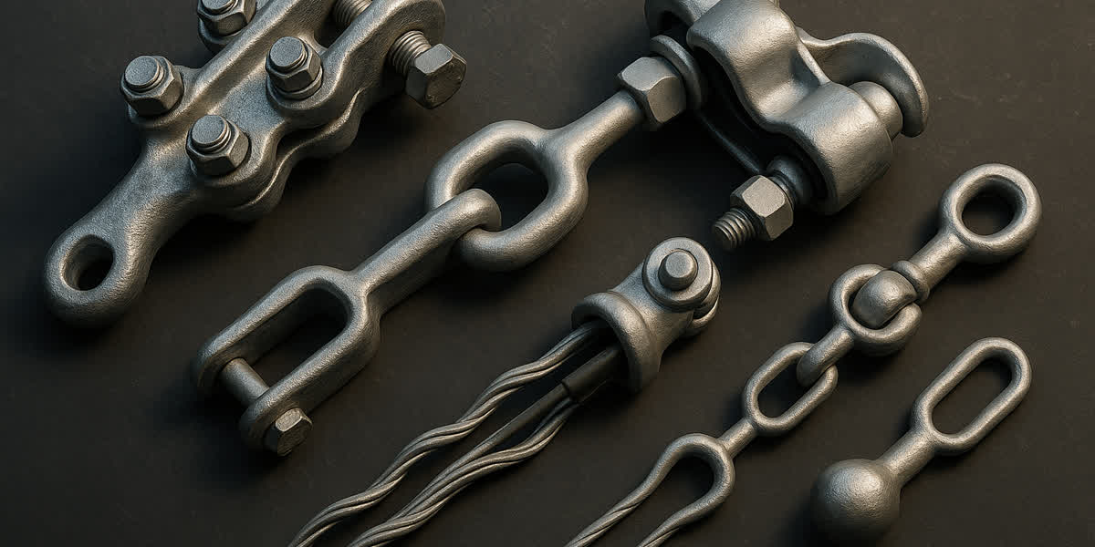
- Armor Grip Suspension & Helical Armor Rods: In C4 and C5 coastal spans, conductors must be shielded at support clamps using high-strength aluminum alloy armor rods. The rods distribute dynamic bending strains and prevent localized galvanic pitting between the suspension clamp and the conductor outer strands. Review our transmission line power fittings & hardware engineered specifically for heavy marine applications.
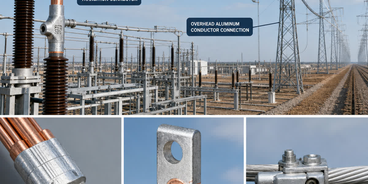
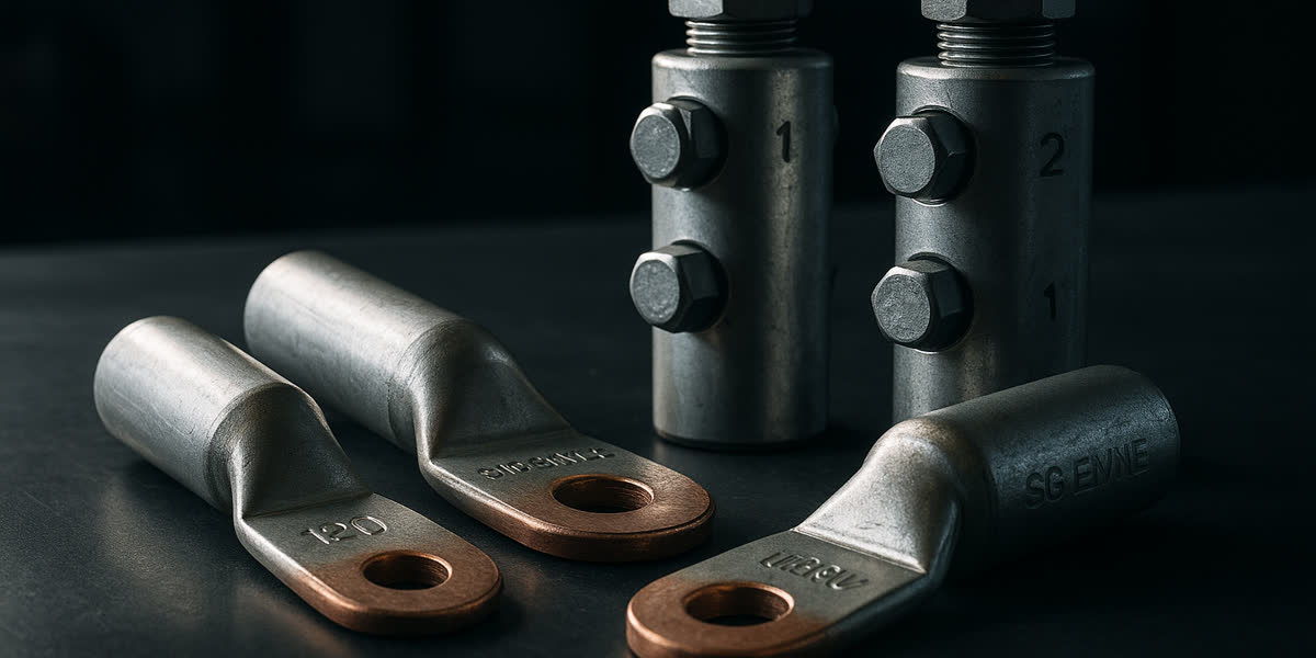
- Bi-Metallic Terminal Transitions: Connecting aluminum transmission conductors directly to copper transformer bushings or substation switchgear creates an immediate galvanic cell. Utility engineers must specify friction-welded bimetallic cable lugs & connectors with factory moisture seals to guarantee long-term joint integrity.
- Neutral Inhibiting Compounds: All bolted parallel-groove (PG) clamps, wedge connectors, and compression splices must be liberally coated with high-viscosity synthetic oxide-inhibiting paste containing suspended zinc or nickel particles to exclude moisture and break residual surface oxides.
7. Manufacturing Excellence & Salt-Spray Quality Control at SiTong Cable
At Zhengzhou Sitong Cable Co., Ltd. (SiTong Cable / 郑州四通电缆), we operate state-of-the-art manufacturing facilities certified under ISO 9001:2015, ISO 14001:2015, and ISO 45001:2018, providing high-reliability overhead conductors to national power utilities across Latin America, Southeast Asia, the Middle East, and Africa.
Our Marine-Grade Conductor Manufacturing Strengths:
- In-Line Vacuum Grease Application: Our advanced rigid tubular and planetary stranding lines feature automated, pressure-controlled vacuum grease injectors. The temperature-regulated grease is distributed homogeneously across all internal wire layers without air entrapment or exterior strand contamination, fully compliant with IEC 61395 Case 1 through Case 4.
- High-Purity Alloy Smelting & Drawing: We utilize 99.7% virgin aluminum ingots and micro-alloyed Al-Mg-Si wire rods drawn under continuous laser micrometer monitoring to ensure strict dimensional tolerances (± 0.01 mm) and uniform metallurgical grain structure.
- 2,000-Hour Salt-Spray & Environmental Verification: All conductor batches undergo rigorous CNAS-accredited laboratory verification, including 2,000-hour continuous neutral salt spray testing (ASTM B117 / IEC 60068-2-11), grease drop-point verification (ASTM D566 ≥ 115°C), zinc coating mass adherence testing (ASTM A90 / ISO 1460), and cyclic mechanical tensile tests.
- Customized Utility Engineering: From custom Case 3 greased ACSR for hurricane-prone coastal grids to high-ampacity AAAC and ACAR designs, our technical department delivers full engineering sag-tension modeling, thermal ratings, and turnkey conductor packages.
8. Frequently Asked Questions (FAQ)
Q1: Why does standard ACSR fail prematurely in coastal marine environments?
Standard ACSR combines hard-drawn aluminum wires over a galvanized steel core. In coastal areas with high humidity and airborne salt, saline electrolyte penetrates between the strands. Once the zinc layer on the steel core is gradually oxidized, a powerful bimetallic galvanic cell forms between the steel core (cathode) and the aluminum strands (anode). This accelerates internal aluminum corrosion, causing invisible structural failure and core rot while the outer layer still appears intact.
Q2: Between AAAC and Greased ACSR, which conductor should be specified for a coastal 220kV transmission line?
For lines located within 5 km of the ocean with standard tower span lengths (250 m to 400 m), AAAC is generally the superior choice because its homogeneous Al-Mg-Si 6201 alloy eliminates internal galvanic corrosion entirely, delivering the lowest total lifecycle cost. However, if the project involves extreme span lengths (> 600 m), river crossings, or severe wind/ice loading requiring ultra-high tensile strength, Greased ACSR (IEC 61395 Case 3) is recommended.
Q3: Does anti-corrosion grease application affect conductor current rating (ampacity) or thermal sag?
Properly formulated conductor grease conforming to IEC 61395 has negligible impact on radial thermal conductivity and does not reduce continuous ampacity. While the internal grease adds approximately 2% to 4% to the total conductor weight (which must be factored into initial sag-tension calculations), it stabilizes the internal electrical contact resistance across strands over decades of service.
Q4: What zinc coating class should be specified for ACSR steel cores in marine applications?
For severe marine environments (ISO 9223 C4/C5), standard Class A zinc coating (200–260 g/m²) is insufficient. Utilities should mandate Class B (400–500 g/m²) or Class C (600–800 g/m²) extra-heavy galvanizing per ASTM A475 / IEC 60888, or specify aluminum-clad steel cores (ACSR/AW) combined with factory grease filling.
Q5: How do bi-metallic transition lugs prevent galvanic corrosion at jumper connections?
Bi-metallic transition lugs are manufactured through solid-state friction welding, joining an electrolytic copper palm to a 99.5% pure aluminum barrel without interfacial voids. This keeps the galvanic copper-aluminum junction hermetically isolated inside the solid metal bond, preventing atmospheric electrolytes from bridging dissimilar metals and eliminating joint overheating and pitting.
9. Summary & Technical Consultation
Protecting overhead power transmission assets from coastal and industrial corrosion demands an integrated approach: matching conductor metallurgy (AAAC, ACAR, or Greased ACSR) to site-specific ISO 9223 corrosivity ratings, enforcing strict IEC 61395 grease application standards, and ensuring full electrochemical compatibility across all transmission hardware.
👉 Browse our complete ACSR conductor range
👉 Explore our high-strength AAAC conductor solutions
👉 Contact our technical engineering team for custom conductor sizing & quotes
📬 Sales inquiries: sales@sitongcable.com | 📞 Phone: +86-371-69176007