AAC Conductor (All Aluminum Conductor) — Complete Technical Guide: BS 215, IEC 61089 & ASTM B231 Standards, Specifications, Selection & Overhead Power Line Applications
All Aluminum Conductor (AAC) is the original and most widely deployed bare overhead conductor type, consisting of multiple stranded layers of EC (Electrical Conductivity) grade aluminum wires. AAC offers the highest conductivity-to-weight ratio of any common overhead conductor, making it the preferred choice for short-to-medium span distribution lines, urban networks, and regions with mild environmental loading. This comprehensive technical guide covers AAC conductor construction, international standards (BS 215, IEC 61089, ASTM B231), electrical and mechanical specifications, selection methodology, and real-world applications in overhead power transmission and distribution systems.
What is AAC Conductor? Construction and Core Components
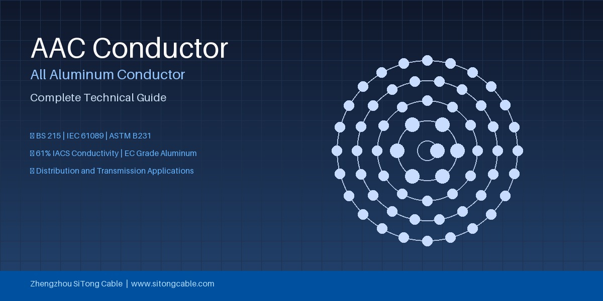
AAC — also known as All Aluminum Conductor or AAC Bare Conductor — is a concentric-lay-stranded conductor made entirely from EC-grade (99.5% minimum purity) aluminum wires. The conductor consists of a single straight central wire surrounded by one or more helical layers of stranded aluminum wires, with successive layers laid in opposite directions to maintain structural stability.
Stranding Construction
The concentric stranding follows established industry patterns:
| Stranding Configuration | Number of Wires | Typical Cross-Section Range | Common Application |
|---|---|---|---|
| 7-wire (1+6) | 7 | 10–50 mm² | Low-voltage service drops, short spans |
| 19-wire (1+6+12) | 19 | 50–200 mm² | Medium-voltage distribution lines |
| 37-wire (1+6+12+18) | 37 | 200–500 mm² | Primary distribution, short transmission |
| 61-wire (1+6+12+18+24) | 61 | 400–800 mm² | Sub-transmission, heavy distribution |
Each AAAC all aluminum alloy conductor uses heat-treated 6201 aluminum alloy for higher strength applications, whereas AAC uses soft EC-grade aluminum for maximum conductivity — typically 61.0% IACS (International Annealed Copper Standard) minimum.
Conductor Materials
The aluminium used in AAC must meet stringent purity and conductivity requirements:
- Aluminium purity: ≥99.5% (EC grade)
- Minimum conductivity: 61.0% IACS (at 20°C)
- Maximum resistivity: 0.028264 Ω·mm²/m (at 20°C)
- Temperature coefficient of resistance: 0.00403/°C
The soft-temper (fully annealed) condition ensures the lowest possible electrical resistance, but this also means AAC has the lowest tensile strength among bare overhead conductors. For spans exceeding 100–150 metres or areas with significant ice/wind loading, engineers typically specify ACSR (Aluminium Conductor Steel Reinforced) or AAAC instead.
International Standards for AAC Conductors
AAC conductors are manufactured and tested to several international standards, depending on the target market and project specification:
BS 215 Part 1 (British Standard)
BS 215:1970 (Part 1: Aluminium Conductors for Overhead Power Transmission) specifies requirements for AAC conductors used in the UK and Commonwealth markets. Key parameters include: - Wire diameters and tolerances - Minimum number of wires per layer - Breaking loads for each standard size - DC resistance at 20°C - Mass per unit length
The standard defines code words and sizes ranging from 16 mm² to 800 mm², with each size assigned a descriptive code word (e.g., Aphis, Aster, Arbutus, Bamboo, Chuckwillow, Coot).
IEC 61089 (International Standard)
IEC 61089:1991 (Round Wire Concentric Lay Overhead Electrical Stranded Conductors) is the international harmonised standard that covers AAC, AAAC, ACSR, and ACAR. For AAC, IEC 61089 specifies: - Standard cross-sectional areas: 16, 25, 35, 50, 70, 95, 120, 150, 185, 240, 300, 400, 500, 630, 800 mm² - Stranding configurations per size - Minimum breaking load (MBL) requirements - DC resistance limits - Overall diameter tolerances
ASTM B231 (North American Standard)
ASTM B231 / B231M (Standard Specification for Concentric-Lay-Stranded Aluminum 1350 Conductors) is the primary AAC standard in the United States and Canada. Key differences from IEC standards: - Uses AWG (American Wire Gauge) or kcmil (thousand circular mils) sizing rather than mm² - Specifies Aluminum 1350-H19 (extra hard) or 1350-O (soft) tempers - Defines the familiar code words: Bluejay, Cardinal, Dipper, Drake, Hawk, Ibis, Lapwing, Linnet, Merlin, Oriole, Partridge, Pheasant, Pigeon, Quail, Raven, Robin, Sparrow, Starling, Teal — all originally defined by the industry-standard code-word system for bare overhead conductors
Other Applicable Standards
| Standard | Region | Scope |
|---|---|---|
| DIN EN 50182 | Europe | Harmonized European standard for overhead conductors |
| AS/NZS 1531 | Australia/New Zealand | Standard for aluminium conductors in overhead lines |
| CSA C49.1 | Canada | Canadian standard for bare overhead conductors |
| JIS C3110 | Japan | Japanese industrial standard for aluminium stranded conductors |
Key Technical Specifications of AAC Conductors
Electrical Properties
The defining electrical characteristic of AAC is its excellent conductivity — the highest of any overhead conductor type at 61.0% IACS minimum:
| Parameter | Value | Notes |
|---|---|---|
| Minimum conductivity | 61.0% IACS | EC-grade aluminium |
| DC resistance at 20°C | 0.028264 Ω·mm²/m | Maximum per IEC 61089 |
| AC resistance at 50 Hz | ~1.02–1.05 × Rdc | Skin effect (increases with size) |
| Capacitive reactance | ~0.07–0.15 μF/km | Depends on spacing and geometry |
| Inductive reactance | ~0.30–0.45 Ω/km | At 50 Hz, 1 metre spacing |
| Current rating (75°C) | See table below | Solar radiation 1000 W/m² |
Mechanical Properties
AAC has the lowest tensile strength of common overhead conductors, which dictates its application range:
| Property | Value |
|---|---|
| Tensile strength (EC grade, soft) | 80–110 MPa |
| Modulus of elasticity | 55–62 GPa |
| Coefficient of linear expansion | 23.0 × 10⁻⁶ /°C |
| Density | 2.703 g/cm³ |
| Maximum continuous operating temperature | 75°C–90°C (standard), 120°C (with high-temperature fittings) |
| Maximum short-circuit temperature | 180°C |
Standard AAC Sizes and Parameters (IEC 61089)
| Nominal Area (mm²) | Stranding (No.×mm) | Overall Diameter (mm) | Approx. Mass (kg/km) | DC Resistance at 20°C (Ω/km) | Min Breaking Load (kN) |
|---|---|---|---|---|---|
| 16 | 7×1.70 | 5.1 | 44 | 1.789 | 2.63 |
| 25 | 7×2.13 | 6.4 | 69 | 1.145 | 4.10 |
| 35 | 7×2.52 | 7.6 | 96 | 0.818 | 5.74 |
| 50 | 7×3.02 | 9.1 | 138 | 0.572 | 8.19 |
| 70 | 19×2.16 | 10.8 | 193 | 0.409 | 11.85 |
| 95 | 19×2.52 | 12.6 | 263 | 0.300 | 16.13 |
| 120 | 19×2.84 | 14.2 | 333 | 0.237 | 20.43 |
| 150 | 19×3.17 | 15.9 | 415 | 0.190 | 25.47 |
| 185 | 19×3.52 | 17.6 | 511 | 0.154 | 31.38 |
| 240 | 37×2.88 | 20.2 | 664 | 0.119 | 40.71 |
| 300 | 37×3.21 | 22.5 | 824 | 0.0955 | 50.60 |
| 400 | 37×3.71 | 26.0 | 1101 | 0.0715 | 67.56 |
| 500 | 61×3.23 | 29.1 | 1376 | 0.0576 | 82.81 |
| 630 | 61×3.63 | 32.7 | 1737 | 0.0455 | 104.60 |
Advantages and Limitations of AAC Conductors
Advantages
- Highest conductivity-to-weight ratio of any overhead conductor (61% IACS at 2.70 g/cm³), meaning maximum current-carrying capacity per unit mass
- Excellent corrosion resistance — aluminium naturally forms a protective oxide layer (Al₂O₃) that resists atmospheric corrosion, making AAC ideal for coastal, industrial, and humid environments
- Lower line losses compared to ACSR of the same cross-section due to no steel core resistance contribution and lower contact resistance between all-aluminium strands
- Easier handling and installation — lighter and more flexible than ACSR, requiring less specialised tooling for stringing and sagging
- Superior recyclability — scrap value for EC-grade aluminium is higher than for composite conductors, reducing life-cycle cost
- Lower radio interference and corona at operating voltages below 132 kV due to smooth surface and uniform conductivity
Limitations
- Lowest tensile strength among overhead conductors, restricting use to spans typically under 150 metres
- Higher sag at elevated temperatures due to the high coefficient of thermal expansion (23 × 10⁻⁶ /°C) and low elastic modulus
- Susceptible to vibration fatigue from aeolian vibration in long spans without adequate damping
- Annealing risk at sustained high temperatures — prolonged operation above 90°C can cause soft-temper AAC to further anneal, reducing strength
Applications of AAC Conductors
AAC conductors are best suited to specific applications where their advantages outweigh their lower mechanical strength:
1. Low-Voltage Distribution Networks (LV)
AAC is the standard conductor for 230/400 V low-voltage overhead distribution lines in urban and suburban areas, where spans are typically short (30–80 m) and mechanical loading is minimal. Lightweight AAC sizes (16–95 mm²) are used for service drops from distribution poles to residential and commercial buildings.
2. Short-to-Medium Span Medium-Voltage Distribution (MV)
For 11 kV and 33 kV distribution lines with spans under 120 m, AAC provides an economical solution with lower line losses than steel-reinforced alternatives. Many municipal utilities in flat-terrain regions standardise on AAC for their MV distribution backbone.
3. Urban and Coastal Environments
In coastal cities where salt-spray corrosion accelerates deterioration of galvanised steel cores in ACSR, AAC's uniform aluminium construction eliminates galvanic corrosion risks entirely. This makes AAC the preferred choice for distribution networks within 10 km of coastlines in many specifications.
4. Industrial Plant Power Distribution
Within industrial complexes, petrochemical plants, and mining sites, AAC is used for short-span overhead feeders where compact size, corrosion resistance, and ease of rerouting are priorities.
5. Temporary and Emergency Power Lines
The light weight and easy handling of AAC make it ideal for temporary construction power supplies, emergency restoration lines, and mobile substation connections where rapid deployment matters more than ultimate strength.
AAC Conductor Selection Guide
When selecting AAC for a new or replacement overhead line, engineers should evaluate the following factors:
Step 1: Determine Current Rating Requirements
Calculate the design current based on: - Maximum load demand (summer peak, future growth allowance) - Voltage drop limits (typically 3–5% for distribution feeders) - Contingency requirements (N-1 or N-2 conditions)
Use the IEEE 738 or CIGRE TB 207 thermal rating method to determine required cross-section. Ambient temperature, solar radiation, wind speed, and emissivity/absorptivity factors must be applied.
Step 2: Verify Span Length and Clearances
AAC is typically limited to spans under 150 m for standard overhead construction. For longer spans, consider upgrading to AACR (aluminium conductor alloy reinforced) or AAAC conductor. Run sag-tension calculations using the conductor's elastic modulus and thermal expansion coefficient at maximum operating temperature (75°C or 90°C) and maximum ice/wind loading to confirm ground clearance compliance.
Step 3: Evaluate Environmental Conditions
| Condition | AAC Suitability | Notes |
|---|---|---|
| Coastal (salt spray) | ✅ Excellent | No galvanic corrosion; natural oxide protection |
| Industrial (chemical) | ✅ Good | Resistant to most atmospheres; avoid caustic alkalis |
| Heavy ice loading | ❌ Poor | Insufficient mechanical strength |
| High wind zones | ⚠️ Moderate | Requires short spans, vibration dampers |
| High altitude (>3000 m) | ⚠️ Moderate | Reduced air density affects heat dissipation |
Step 4: Compare Life-Cycle Cost
Although AAC has higher initial material cost per ampacity than ACSR in long spans, the total life-cycle cost (including installation, maintenance, losses, and end-of-life scrap value) can be lower — particularly for coastal installations where ACSR requires galvanised steel core replacement or upgraded corrosion protection.
Installation Best Practices for AAC Conductors
Proper installation is essential to achieving the 40+ year service life expected from AAC overhead lines:
Stringing and Sagging
- Pulling tension: Never exceed 20% of the conductor's rated breaking strength during stringing
- Sight sag: Always refer to sag-tension tables computed for the specific conductor size, span length, and ambient temperature. Use dynamic sagging methods (dynamometer + transit) for spans over 100 m
- Sag at final tension: Typically 15–18% of RBS (Rated Breaking Strength) at 15°C with no wind/ice
- Roller size: Sheave diameter must be at least 20× the conductor diameter to avoid bending stress
Connector Selection
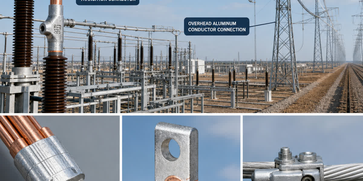
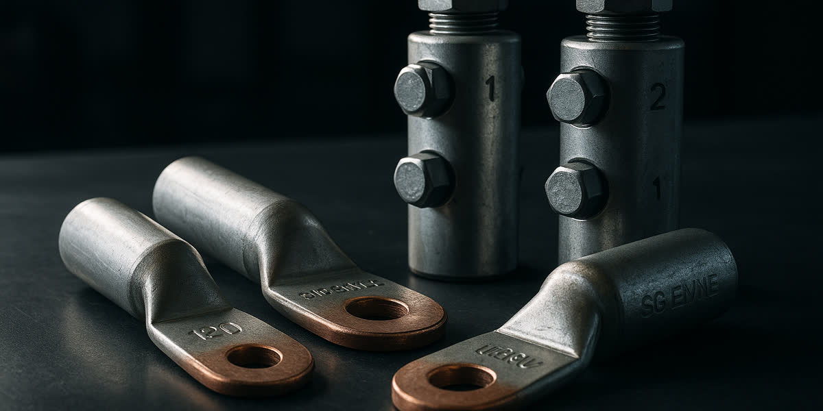
- Use all-aluminium compression connectors (not bi-metallic or tin-plated copper) to avoid galvanic corrosion
- Connector must match the conductor diameter exactly — AAC outer strands compress differently than ACSR due to the softer core
- Apply oxide-inhibiting compound (AAC-800 or equivalent) to all connector interfaces before compression
- Follow manufacturer's crimping specifications (number of crimps, compression pressure, die size) precisely
Damping and Hardware
- Install Stockbridge-type vibration dampers on spans exceeding 100 m or as recommended by the line design standard
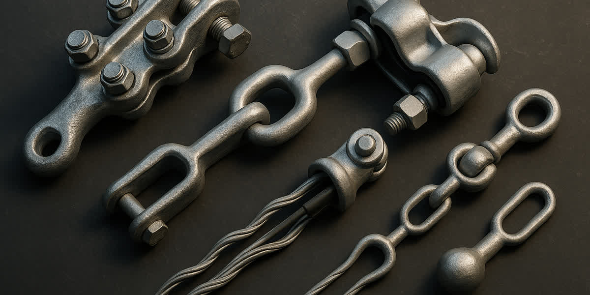
- Use aluminium armour rods at suspension points to distribute clamping pressure and prevent fatigue
- Corona rings may be required for AAC on systems above 132 kV
Comparison: AAC vs AAAC vs ACSR
| Parameter | AAC | AAAC | ACSR |
|---|---|---|---|
| Conductivity (% IACS) | 61.0% | 53.0–53.5% | 40–53% (varies by Al/steel ratio) |
| Tensile strength | Lowest | High (315 MPa+ for 6201) | Highest (depends on steel content) |
| Weight | Lowest per ampacity | Moderate | Heaviest |
| Corrosion resistance | Excellent | Excellent | Moderate (steel core vulnerable) |
| Sag at high temp | High | Lower | Lowest (steel handles tension) |
| Span length | Short (<150 m) | Medium (up to 300 m) | Long (300 m+) |
| Typical cost | Moderate | Moderate-high | Low-moderate |
| Common applications | LV/MV distribution, coastal | Long-span distribution, industrial | Transmission lines, long spans |
Frequently Asked Questions (FAQ)
1. What is the maximum current an AAC 240 mm² conductor can carry?
An AAC 240 mm² conductor (37-wire, 2.88 mm per wire) has a typical continuous current rating of approximately 450–520 A at 75°C under standard conditions (35°C ambient, 0.6 m/s wind, 1000 W/m² solar radiation, 0.5 emissivity/absorptivity). The exact rating depends on local environmental factors and should be verified using IEEE 738 or the manufacturer's thermal rating tables. For higher ampacity, consider increasing to AAC 300 mm² (≈520–600 A) or switching to AACR/AAAC conductor.
2. What is the difference between AAC and AAAC conductor?
The fundamental difference is material: AAC uses EC-grade (99.5% pure) aluminium in soft temper with 61% IACS conductivity and lower tensile strength (~80–110 MPa), while AAAC uses heat-treated aluminium alloy 6201 (Al-Mg-Si) with 53% IACS conductivity but much higher tensile strength (~315 MPa). AAAC is the correct choice when higher mechanical strength is needed within a similar weight budget, whereas AAC is superior when maximum conductivity per unit mass is the priority.
3. Can AAC conductor be used for long-span transmission lines?
AAC is generally not recommended for transmission lines with spans exceeding 150 metres. The combination of low tensile strength and high thermal expansion coefficient results in excessive sag at maximum operating temperature, which can violate ground clearance requirements. For transmission applications, ACSR (with its galvanised steel core) or AAAC (with its higher-strength alloy) are the standard choices. However, AAC can be used in sub-transmission (33–66 kV) with short span lengths and adequate clearance margins.
4. What standards govern AAC conductor manufacturing?
AAC conductors are manufactured to several international standards depending on the target market: BS 215 Part 1 (UK/Commonwealth), IEC 61089 (international), ASTM B231 (North America), DIN EN 50182 (Europe), AS/NZS 1531 (Australia/New Zealand), and CSA C49.1 (Canada). All standards specify minimum EC-grade aluminium purity (99.5%), conductivity (61% IACS minimum), concentric stranding configurations, breaking loads, and DC resistance limits. SiTong Cable manufactures AAC in compliance with all major international standards.
5. Does AAC conductor corrode in coastal environments?
AAC has excellent resistance to atmospheric corrosion due to the self-passivating aluminium oxide layer (Al₂O₃) that forms naturally on exposure to air. In coastal environments, AAC actually outperforms ACSR because there is no steel core to suffer galvanic or chloride-induced corrosion. However, direct contact with dissimilar metals (copper, brass, galvanised steel) should be avoided unless proper bi-metallic connectors are used, as this can cause galvanic corrosion at the junction. For the most demanding coastal applications, AAC with an extra layer of grease-filled corrosion protection is available.
For project-specific AAC conductor requirements, including custom stranding configurations, special tempers, or large cross-sections up to 800 mm², contact the SiTong Cable engineering team for detailed technical proposals and sag-tension calculations.