Cable de Potencia (Media Tensión y Baja Tensión) — Guía Técnica Completa: Normas IEC 60502, BS 6622 e ICEA S-93-639, Especificaciones, Construcción, Selección y Aplicaciones para Distribución Eléctrica
Cable de Potencia (Media Tensión y Baja Tensión) — Guía Técnica Completa: Normas IEC 60502, BS 6622 e ICEA S-93-639, Especificaciones, Construcción, Selección y Aplicaciones para Distribución Eléctrica
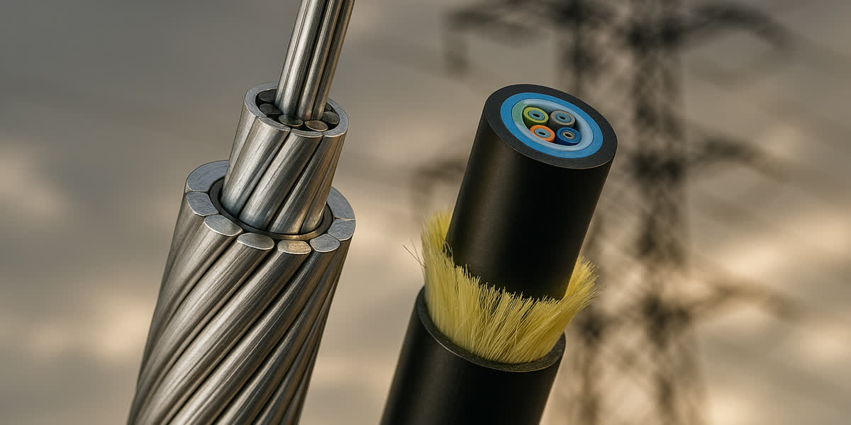
Los cables de potencia constituyen la columna vertebral de todo sistema de distribución eléctrica, transportando energía desde las subestaciones hasta instalaciones industriales, edificios comerciales y desarrollos residenciales. A diferencia de los conductores aéreos desnudos utilizados en líneas de transmisión, los cables de potencia están completamente aislados y revestidos para instalación subterránea, en ductos, bandejas portacables o despliegue submarino. Esta guía técnica integral cubre la construcción de cables de potencia, normas internacionales (IEC 60502-2, BS 6622, ICEA S-93-639), materiales aislantes (XLPE, EPR, PVC), tipos de conductor (cobre y aluminio), clasificaciones de tensión, metodología de selección y aplicaciones prácticas en redes de distribución de BT y MT.
¿Qué es un Cable de Potencia? Componentes y Construcción
Un cable de potencia es un conjunto de uno o más conductores eléctricos aislados, encerrados en una cubierta protectora, diseñado para transportar corriente nominal continua a niveles de tensión especificados. A diferencia de los conductores aéreos desnudos que dependen del aire como aislamiento, los cables de potencia utilizan materiales dieléctricos sólidos para proporcionar aislamiento eléctrico, protección mecánica y sellado ambiental.
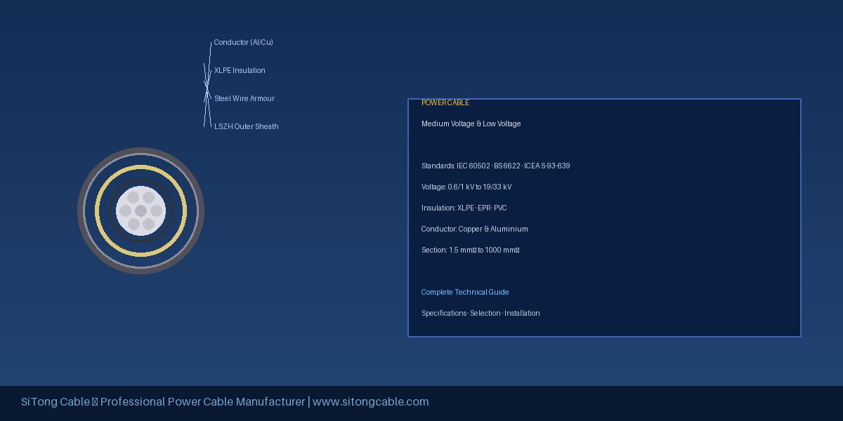
Capas de Construcción
| Capa | Material | Función |
|---|---|---|
| Conductor | Cobre (recocido/estañado) o Aluminio | Elemento transportador de corriente |
| Pantalla del conductor | XLPE/EPDM semiconductor | Distribución uniforme del campo eléctrico |
| Aislamiento | XLPE, EPR o PVC | Aislamiento dieléctrico conductor-tierra |
| Pantalla del aislamiento | XLPE/EPDM semiconductor | Gradación del esfuerzo eléctrico |
| Blindaje metálico | Cinta de cobre, alambre o vaina de plomo | Retorno de corriente de fallo, protección mecánica |
| Base | PVC o PE | Barrera térmica, protección del blindaje |
| Armadura | Alambre acero galvanizado / alambre aluminio | Protección mecánica contra impactos |
| Cubierta exterior | PVC, PE, LSZH | Protección ambiental general |
Clasificaciones de Tensión
| Clase | U₀/U (kV) | Aplicación Típica |
|---|---|---|
| Baja Tensión (BT) | 0.6/1 kV | Cableado de edificios, distribución industrial, residencial |
| Media Tensión (MT) | 3.6/6 kV a 19/33 kV | Distribución primaria, plantas industriales, parques eólicos |
| Alta Tensión (AT) | 38/66 kV y superiores | Subtransmisión, grandes complejos industriales |
SiTong Cable se especializa en cables de potencia de BT (0.6/1 kV) y MT (hasta 33 kV), fabricados según los estándares internacionales más exigentes.
Normas Internacionales
IEC 60502 (Norma Internacional)
La serie IEC 60502 es la norma internacional principal para cables de potencia dieléctricos extruidos de 1 kV a 30 kV: Parte 1 cubre cables BT (0.6/1–3 kV), Parte 2 cubre cables MT (6–30 kV). Requisitos clave: secciones de conductor 10–1600 mm² (cobre) y 16–1600 mm² (aluminio), prueba de descargas parciales ≤5 pC a 1.5U₀, tensión de impulso 95–125 kV pico.
BS 6622 (Norma Británica)
BS 6622:2014 cubre cables de potencia armados con aislamiento XLPE para tensiones nominales de 3.6/6 kV a 19/33 kV, utilizados principalmente en Reino Unido, Commonwealth y Oriente Medio. Especifica tipos de armadura (SWA, AWA), requisitos de comportamiento al fuego y parámetros de capacidad de corriente según BS 7671.
ICEA S-93-639 (Norma Norteamericana)
ICEA S-93-639 cubre cables dieléctricos extruidos de 5–46 kV para los mercados de EE. UU. y Canadá. Utiliza dimensionamiento en kcmil, niveles de aislamiento 100%/133%/173%, XLPE retardante de arborización (TR-XLPE) y cubiertas PVC (Tipo II), PE (Tipo III) o LSZH (Tipo IV).
| Norma | Rango Tensión | Región | Características Clave |
|---|---|---|---|
| IEC 60502 | 0.6/1 – 30 kV | Internacional | Estándar general, prueba PD obligatoria |
| BS 6622 | 3.6/6 – 19/33 kV | Reino Unido/Medio Oriente | SWA/AWA, rendimiento al fuego |
| ICEA S-93-639 | 5–46 kV | Norteamérica | 100/133/173% aislamiento, TR-XLPE |
| AS/NZS 1429 | 0.6/1 – 19/33 kV | Australia/NZ | Clasificación armónica, resistencia a incendios |
Materiales Aislantes
XLPE (Polietileno Reticulado)
El XLPE domina más del 85% del mercado global de cables MT. Temperatura de servicio continuo 90°C (emergencia 130°C, cortocircuito 250°C), constante dieléctrica 2.3–2.5. Ventaja clave: excelente estabilidad termomecánica. Punto débil: susceptibilidad a arborización acuosa (mitigada por TR-XLPE y fabricación por curado seco).
EPR (Caucho de Etileno-Propileno)
El EPR se utiliza donde se requiere mayor flexibilidad o temperatura: 105°C continuo (emergencia 140°C), excelente flexibilidad a baja temperatura, ideal para minería, puertos e instalaciones en climas fríos.
PVC (Cloruro de Polivinilo)
El PVC se utiliza principalmente para cables BT (0.6/1 kV): bajo costo, datos históricos extensos, facilidad de empalme. Limitaciones: pérdidas dieléctricas más altas, limitado a BT, contenido de halógenos (produce HCl en incendio).
Especificaciones Técnicas Clave
Capacidad de Corriente (Ampacidad) — Valores de Referencia
(Cables 3 núcleos XLPE armados, 30°C ambiente, en bandeja, disposición trébol)
| Sección Conductor | Cobre (A) | Aluminio (A) |
|---|---|---|
| 16 mm² | 110 | 85 |
| 70 mm² | 270 | 210 |
| 120 mm² | 370 | 285 |
| 240 mm² | 510 | 395 |
| 400 mm² | 650 | 500 |
Factores de reducción obligatorios: temperatura ambiente >30°C, agrupamiento de cables, profundidad de enterramiento, resistividad térmica del suelo (ρ > 1.2 K·m/W), corrientes armónicas.
Temperaturas de Cortocircuito
| Aislamiento | Temp. Máx. | Densidad Corriente CC (Cu) |
|---|---|---|
| PVC (70°C nominal) | 160°C | ~150 A/mm² |
| XLPE (90°C nominal) | 250°C | ~230 A/mm² |
| EPR (105°C nominal) | 280°C | ~260 A/mm² |
Guía de Selección
Paso 1: Determinar Requisitos de Tensión
Identificar la tensión del sistema (U₀/U) y seleccionar un cable con tensión nominal igual o superior. Para MT, verificar el nivel de impulso (BIL).
Paso 2: Calcular Corriente Continua
Seleccionar sección con ampacidad ≥125% de la corriente a plena carga para motores, o ≥100% para cargas resistivas continuas. Aplicar todos los factores de reducción.
Paso 3: Verificar Caída de Tensión
Para BT, la caída no debe exceder 3–5%. Fórmula para trifásica: ΔV = √3 × I × L × (R cos φ + X sin φ)
Paso 4: Verificar Cortocircuito
Sección mínima (mm²) = Iₖ × √t / k (k=143 para cobre XLPE, k=94 para aluminio XLPE).
Paso 5: Seleccionar Construcción
| Instalación | Recomendación |
|---|---|
| Enterramiento directo | Armadura SWA/AWA, cubierta PE |
| Bandeja interior | Sin armadura o armadura de alambre, LSZH |
| Ducto subterráneo | Según tensión de tiro |
| Zona peligrosa | Armado, EPR, LSZH |
| Submarino | Doble armadura alambre, PE, bloqueo de agua |
Paso 6: Factores Ambientales
Especificar cables LSZH para túneles y edificios altos. Cubierta CSP para exposición a hidrocarburos. Cubierta PE con negro de carbón para exterior (UV). Combinar con selección de cables de control para aplicaciones de flexibilidad especial.
Accesorios para Cables de Potencia
Terminales Termocontráctiles (Interior/Exterior)
Interior: distancia de fuga 12–16 mm/kV. Exterior: 25–31 mm/kV (con faldones de silicona antirrastreo).
Terminales y Empalmes Fríos
Cuerpos de silicona preexpandidos que se contraen al retirar el núcleo de soporte. Ventajas: instalación consistente, sin fuente de calor, excelente resistencia al rastreo.
Empalmes Rectos
| Tipo | Tensión | Característica |
|---|---|---|
| Termocontráctil | BT y MT (≤33 kV) | Tecnología probada, bajo costo |
| Frío | MT (6–33 kV) | Calidad consistente |
| Resina colada | BT (0.6/1 kV) | Protección mecánica total, impermeable |
| Premoldeado | MT (12–33 kV) | Probado en fábrica, máxima fiabilidad |
Mejores Prácticas de Instalación
Tiro de cables: Tracción máxima ≤50 N/mm² para Cu, ≤30 N/mm² para Al. Presión lateral máxima 500 kg/m.
Radio de curvatura mínimo: BT sin armar 6×OD, BT armado 8×OD, MT unipolar sin armar 15×OD, MT tripolar armado 12×OD.
Empalmes: Entorno limpio y seco; eliminar humedad entre hilos conductores; cinta semiconductora con solape del 50%; conectores mecánicos con llave dinamométrica (±5%); prueba de aislamiento con megóhmetro 5 kV (>1000 MΩ).
Preguntas Frecuentes (FAQ)
1. ¿Cuál es la diferencia entre cables BT, MT y AT?
Los cables BT tienen tensión nominal ≤1 kV (típicamente 0.6/1 kV) para cableado de edificios e industrial. Los cables MT van de 3.6/6 kV a 19/33 kV para redes de distribución primaria. Los cables AT superan 33 kV para subtransmisión. Diferencias clave: espesor del aislamiento (BT 3–4 mm, MT 5.5–10.5 mm), pruebas (descargas parciales obligatorias en MT/AT) y complejidad de accesorios.
2. ¿Cuándo elegir conductor de cobre sobre aluminio?
Cobre cuando: el espacio es limitado (misma ampacidad, ~40% menos sección), terminaciones frecuentes (conectores de cobre más fiables), cargas cíclicas con picos altos. Aluminio cuando: el peso importa (~50% más ligero), presupuesto ajustado (50–65% menos costo por ampacidad), recorridos largos (sección grande controla caída de tensión). Para cables MT >120 mm², el aluminio es la opción económica y práctica por defecto.
3. ¿Cuál es la vida útil típica de un cable XLPE?
Un cable XLPE correctamente fabricado, instalado y operado tiene una vida útil de 30–40 años (BT) y 35–45 años (MT). Cada 10°C por encima de 90°C reduce la vida del aislamiento a la mitad (Arrhenius). Los materiales TR-XLPE modernos y los procesos de curado seco han extendido la vida esperada a más de 50 años.
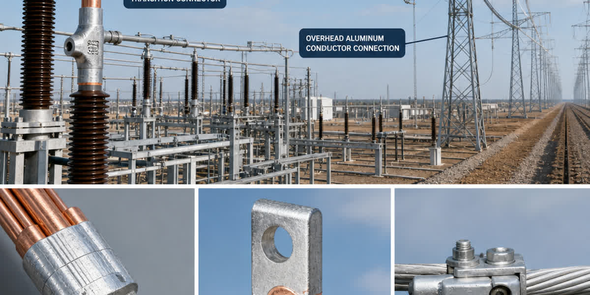
4. ¿Se pueden conectar conductores de aluminio y cobre directamente?
No deben conectarse directamente sin un conector bimetálico. El contacto directo causa corrosión galvánica debido a la diferencia de potencial (~1.2 V entre Al y Cu). Usar: (a) terminales bimetálicos Al-Cu (soldados por fricción), (b) terminales de cobre estañado (el estaño actúa como barrera), o (c) terminales de aluminio con compuesto inhibidor de óxido. En todos los casos, aplicar compuesto anticorrosión (Penetrox A, Kopr-Shield).
5. ¿Qué significa LSZH (Low Smoke Zero Halogen) en cables de potencia?
LSZH (también LSOH, OHLS o ZH) se refiere a compuestos de cubierta y aislamiento que emiten humo mínimo (<5% de oscurecimiento durante la combustión) y ningún gas halógeno (HCl, HF, HBr) al exponerse al fuego. Es crítico para túneles (carretera, ferrocarril), rascacielos (rutas de evacuación), plataformas marinas, centros de datos y espacios públicos. Los cables LSZH (BS 7629, IEC 60332-3, IEC 60754-1/2) también presentan menor propagación de llama y daño corrosivo reducido a equipos electrónicos sensibles.
Para requisitos específicos de cables de potencia — secciones personalizadas, configuraciones de armadura, materiales de cubierta especiales o generación de listas de cables con cálculos de ampacidad — contacte al equipo de ingeniería de SiTong Cable. Fabricamos cables BT y MT según normas IEC, BS e ICEA, con secciones de 1.5 mm² a 1000 mm² y tensiones nominales hasta 33 kV.