Overhead Transmission Line Design for Long Spans and River Crossings: Conductor Selection, Sag-Tension Analysis, Aeolian Vibration Damping and Hardware Engineering
Overhead Transmission Line Design for Long Spans and River Crossings: Conductor Selection, Sag-Tension Analysis, Aeolian Vibration Damping and Hardware Engineering
Designing overhead transmission lines across major geographic barriers—such as wide navigable rivers, sea channels, deep ravines, and lake crossings—represents one of the most demanding disciplines in power grid engineering. Long-span crossings (typically defined as single spans exceeding 500 meters up to 2,000+ meters without intermediate support towers) operate under mechanical and aerodynamic stresses far exceeding standard transmission line segments. Engineers must balance extreme static tension, massive dynamic wind and ice loads, stringent navigational clearance limits, severe Aeolian vibration fatigue, and long-term creep without compromising electrical ampacity.
Zhengzhou SiTong Cable Co., Ltd. (SiTong Cable), an international tier-1 manufacturer of high-tensile bare overhead conductors and specialized transmission line solutions, manufactures engineered conductor variants designed specifically to meet international standards including IEC 60826, IEC 61089, ASTM B232, ASTM B399, and CIGRE Technical Brochure 273. This comprehensive technical guide provides electrical and structural engineers with an in-depth framework for conductor selection, catenary sag-tension calculations, everyday stress (EDS) design, aerodynamic vibration mitigation, and specialized line hardware configurations for critical crossing spans.
1. Core Engineering Challenges in Long-Span and River Crossings
Standard transmission spans typically range from 250 m to 400 m with conductor everyday stress levels maintained between 18% and 22% of Rated Tensile Strength (RTS). In river and valley crossings, span lengths increase threefold to sixfold, introducing severe physical constraints:
- Extreme Mechanical Tension and Tower Loading: To maintain statutory navigational clearances above high-water levels without building excessively tall crossing towers (which can exceed 150–300 meters in height), conductors must be pulled to significantly higher horizontal tensions. This shifts Everyday Stress (EDS) into the 25%–35% RTS zone, radically elevating the risk of fatigue failure.
- Amplified Wind and Ice Load Combinations: In broad open river valleys and coastal straits, surface roughness is low, resulting in sustained high laminar wind speeds. Combined ice and wind loading per IEC 60826 or NESC Heavy Loading rules imposes massive transverse and vertical loads on conductor strands and dead-end towers.
- Severe Aeolian Vibration and Sub-Span Oscillation: High conductor tension directly suppresses self-damping capability while increasing the vulnerability to vortex-shedding Aeolian vibration ($f = 0.185 \cdot V / d$, spanning 5 Hz to 50 Hz). Open water surfaces create steady, low-turbulence wind fields ideal for continuous high-energy vibration that causes inter-strand fretting fatigue at suspension clamps.
- Thermal Elongation and Sag Sensitivity: Long catenary curves exhibit high geometric amplification: a slight increase in operating temperature or metallurgical creep results in large vertical sag increases, threatening navigational safety.
- Atmospheric and Galvanic Corrosion in River/Marine Estuaries: River crossings, particularly near tidal estuaries, expose conductors to aggressive industrial moisture, salt spray, and sulfur compounds, demanding advanced galvanic corrosion protection between aluminum and steel components.
2. Long-Span Conductor Family Comparison and Selection Matrix
Selecting the optimal conductor structure requires an analytical trade-off between ultimate tensile strength, strength-to-weight ratio ($RTS / w$), modulus of elasticity ($E$), thermal expansion coefficient ($\alpha$), and high-frequency self-damping properties.
| Conductor Type | Standard Designation | Typical Stranding / Core Ratio | Strength-to-Weight Ratio (km) | Modulus of Elasticity ($E$, GPa) | Thermal Coeff. ($\alpha$, $10^{-6}/^\circ\text{C}$) | Primary Crossing Application |
|---|---|---|---|---|---|---|
| High-Strength ACSR | ACSR Conductor (ASTM B232 / IEC 61089) | 54/19, 54/7, 26/7 (Extra High Tensile Steel) | 7.5 – 10.5 | 77 – 85 | 17.5 – 19.3 | Standard and heavy river crossings (500m–1200m) |
| All Aluminum Alloy | AAAC Conductor (ASTM B399 / EN 50182) | 37, 61, 91 (Al-Mg-Si 6201-T81) | 8.0 – 9.2 | 57 – 64 | 23.0 | Medium river spans (400m–800m) in high-corrosion coastal zones |
| Annealed Steel-Supported | ACSS and ACSS/TW (ASTM B856 / ASTM B857) | 54/19 Trapezoidal (HS / EHS Steel Core) | 8.5 – 11.0 | 79 – 88 | 15.3 – 17.0 | High-capacity crossings with strict sag limits and self-damping |
| Gap-Type Super Thermal | G(S)TACSR / GAP (IEC 62004) | Thermal Al-Zr alloy over greased steel core | 9.0 – 12.0 | 95 – 105 (knee-point) | 11.5 (above knee-point) | Ultra-long spans (1000m–2000m+) requiring low thermal sag |
| Galvanized Steel Strand | Galvanized Steel Wire (ASTM A475 / IEC 60888) | 7, 19, 37 Extra High / Ultra High Tensile | 12.0 – 15.0 | 175 – 195 | 11.5 | High-strength earth wires, guy stays and river crossing ground shields |
| Optical Ground Wire | OPGW Cable (IEEE 1138 / IEC 60794-4) | Stainless Steel Tube + ACS / AA Wires | 9.0 – 11.5 | 90 – 120 | 13.0 – 15.5 | Combined lightning shield and high-speed grid fiber communications |
In-Depth Conductor Evaluation
- High-Strength ACSR (Custom High-Steel Core Ratio): By deploying class A, B, or ultra-high-strength steel cores (tensile strength up to 1,770–1,960 MPa) with 54/19 or 45/7 stranding configurations, ACSR conductors deliver exceptional mechanical load capacity. For river crossing environments, SiTong Cable applies special high-temperature blocking grease conforming to IEC 61394 across all inner steel and aluminum layers to prevent moisture ingress and electrolytic corrosion.
- AAAC Conductor (Al-Mg-Si Alloy 6201-T81): AAAC conductors feature a uniform metallurgical composition throughout all layers, completely eliminating bimetallic galvanic corrosion. While their modulus of elasticity is lower than ACSR, their superior strength-to-weight ratio and surface hardness make them ideal for wide coastal estuary crossings where salt fog is intense.
- ACSS and Trapezoidal Wire (ACSS/TW): Using fully annealed aluminum strands over a high-strength steel core, ACSS transfers virtually all mechanical tension to the steel core under heavy loading. Furthermore, the interstitial space in trapezoidal stranding provides significant inter-layer friction, creating superior self-damping properties that suppress Aeolian vibrations.
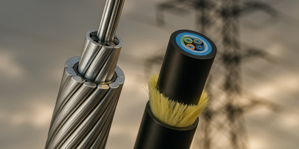
- Crossing Ground Shielding and Communications: Crossing towers must be protected by high-reliability earth shielding. High-strength galvanized steel wire strands and optical OPGW cables with heavy Aluminum-Clad Steel (ACS) wire layers ensure both high fault-current carrying capacity and mechanical integrity under direct lightning strikes.
3. Sag-Tension Calculation and Everyday Stress (EDS) Design
Accurate sag-tension modeling over long crossings requires rigorous application of catenary mechanics rather than standard parabolic approximations.
Catenary Equations for Long Spans
The exact catenary curve of a conductor suspended between two level supports separated by span $L$ is expressed as:
$$y(x) = C \left( \cosh\left(\frac{x}{C}\right) - 1 \right) \approx \frac{x^2}{2C} + \frac{x^4}{24C^3}$$
Where: - $C = \frac{H}{w_c}$ is the catenary parameter (meters). - $H$ is the horizontal component of conductor tension (N). - $w_c$ is the resultant unit weight of the conductor under gravity, ice, and wind (N/m).
The maximum mid-span sag $D_{max}$ and conductor arc length $S$ are:
$$D_{max} = C \left( \cosh\left(\frac{L}{2C}\right) - 1 \right)$$ $$S = 2C \sinh\left(\frac{L}{2C}\right)$$
When tower support elevations differ by $\Delta h = h_2 - h_1$ (inclined span), the lowest point of the catenary shifts toward the lower tower by $x_0 = \frac{L}{2} - \frac{C \cdot \Delta h}{L}$, significantly altering the vertical load distribution between the two crossing towers.
Ruling Span vs. Actual Isolated Span
Because long river crossings are structurally isolated between strain (dead-end) anchor towers on either bank, they cannot rely on tension equalization across adjacent suspension spans. The crossing span must be calculated as an isolated actual span, accounting for the full mechanical stiffness of the dead-end insulator strings and tower deflection under maximum wind and ice conditions.
Everyday Stress (EDS) Limits and CIGRE Safe Design Criteria
Per CIGRE Technical Brochure 273 and IEEE standards, conductor fatigue life is governed by the ratio of horizontal tension ($H$) to conductor weight ($w$) and the parameter $H / RTS$:
$$\text{CIGRE Vibration Risk Parameter}: \frac{H}{w} \quad (\text{meters})$$
- Un-damped Standard Lines: Safe $H/w \le 1,000\text{ m}$ (typically $18\% \text{ RTS}$).
- Long River Spans with Stockbridge Dampers: $H/w$ reaches $1,400\text{ m} – 2,200\text{ m}$ ($22\% – 28\% \text{ RTS}$).
- River Spans with Dampers + Armor Grip Suspension (AGS): $H/w$ up to $2,400\text{ m} – 2,800\text{ m}$ ($28\% – 32\% \text{ RTS}$).
Under severe winter conditions (minimum temperature with no wind), tension must not exceed $33\% – 36\% \text{ RTS}$, while under peak design wind/ice loading (IEC 60826 50-year return period), maximum working tension must remain below $50\% – 60\% \text{ RTS}$ to preserve an adequate safety factor against strand failure.
4. Aerodynamic Phenomena and Vibration Damping Systems
Long river crossings represent the most critical aerodynamic environment for overhead lines. Open water surfaces provide uniform, laminar horizontal wind velocity profiles with minimal turbulence, creating maximum energy transfer from wind to conductor.
Wind Velocity (V) --->  ( ( Vortex Shedding ) )  ---> Conductor Vibration (f = 0.185 * V / d)
                              |
                     [Standing Waves]
                              |
    ------------------[Stockbridge Damper]------------------[Armor Grip Suspension (AGS)]
    [High Bending Stress at Clamps Absorbed & Dissipated via Resonant Counter-Masses]
Aerodynamic Instability Types
- Aeolian Vibration (5–50 Hz): Low-velocity laminar winds (1–7 m/s) generate alternating Karman vortices behind the conductor. When the vortex shedding frequency matches a natural resonant harmonic of the span, standing waves build up. At high everyday tensions, high bending stresses at suspension clamps cause fretting fatigue in outer aluminum strands.
- Sub-Span Oscillation (0.5–3 Hz): Occurs in bundled conductors (twin, quad, or six-bundle configurations) where the wake from the windward sub-conductor creates an aerodynamic lift/drag instability on the leeward sub-conductor.
- Conductor Galloping (0.1–1 Hz): Low-frequency, large-amplitude vertical whipping caused by moderate to strong winds acting on asymmetric ice deposits on the conductor surface.
Engineering Damping Solutions
To ensure a 40+ year operating life without fatigue failure, long spans must employ a multi-tiered vibration protection system:
- Multi-Frequency Stockbridge Dampers: Installing 4 to 8 tuned Stockbridge dampers per span per phase. Dampers feature asymmetrical bell masses and flexible Messenger stranded wire cables designed to dissipate vibration energy across the full 5–50 Hz frequency spectrum.
- Armor Grip Suspension Units (AGS): Replaces traditional rigid trunnion suspension clamps with elastomeric neoprene cushions enclosed in preformed helical aluminum armor rods. This distributes dynamic bending stresses over a span of 1.5–2.0 meters, reducing peak stress concentration at the clamp vertex by up to 65%.
- Spacer Dampers for Bundled Conductors: On bundled river crossings, rigid spacers must be replaced by elastomeric damped spacer dampers placed at non-uniform sub-span intervals (e.g., 35m, 42m, 38m, 45m) to break acoustic wave resonance and suppress sub-span flutter.
5. Specialized Hardware and Line Fittings for Crossing Spans
Hardware for long-span river crossings must carry massive tensile forces while maintaining electrical conductivity and preventing corona discharge under high-voltage operating conditions. Engineers must specify certified power fittings and hardware engineered for high-load duty:
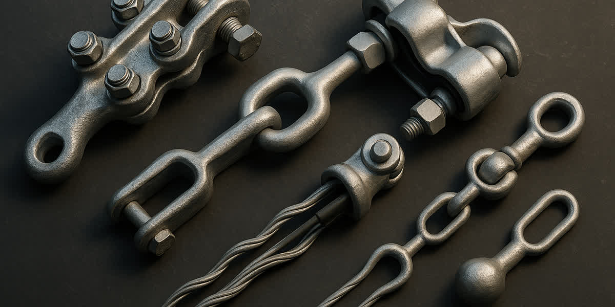
- Quadrant Strain Clamps and Compression Dead-Ends: Compression dead-end assemblies for high-strength ACSR utilize a two-part compression design: an internal high-strength forged steel sleeve compressed onto the steel core using hydraulic presses (100–200 ton force), surrounded by an outer aluminum compression body to conduct phase current.
- Heavy-Duty Anchor Shackles and Yoke Plates: Grade 80 forged alloy steel clevises, ball-eyes, and multi-string yoke plates rated for 210 kN, 300 kN, 400 kN, or 500 kN ultimate mechanical strength per string.
- Corona Shielding Rings: At crossing towers exceeding 220 kV, 400 kV, or 500 kV, large-diameter toroidal corona rings protect insulator strings and dead-end hardware from localized dielectric breakdown and radio interference.
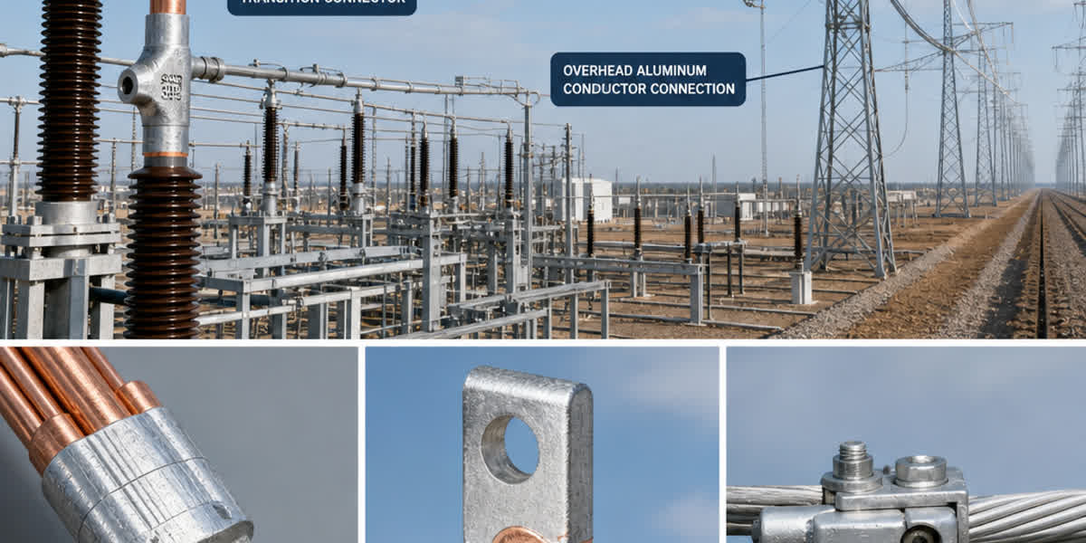
- Terminal Connectors and Jumpers: Flexible jumper loops utilizing high-conductivity cable lugs & compression terminals ensure zero electrical overheating across strain tower bypasses.
6. Engineering Case Study: 1,150-Meter 220kV River Crossing
Project Parameters and Environmental Conditions
- Nominal Voltage: 220 kV Double Circuit (Twin Bundle per Phase, 450 mm bundle spacing)
- Crossing Span Length ($L$): 1,150 meters (Level supports, tower height = 118 m)
- Required Navigational Clearance ($H_{clear}$): 38.0 meters above 100-year maximum flood water level
- Design Wind Speed: $V_{max} = 34.0\text{ m/s}$ (10-minute mean at 10m height, terrain category B)
- Design Radial Ice Thickness: 10 mm ($w_{ice} = 900\text{ kg/m}^3$)
- Ambient Temperature Range: $-15^\circ\text{C}$ to $+45^\circ\text{C}$ (Everyday Mean $= +15^\circ\text{C}$)
Tower A (118m)                                                           Tower B (118m)
  |===|                                                                    |===|
  |   |=========== Twin Bundle ACSR Conductor (L = 1150m) ================|   |
  |   |     ~ ~ ~ ~ ~ ~ ~ ~ ~ ~ ~ ~ ~ ~ ~ ~ ~ ~ ~ ~ ~ ~ ~ ~ ~ ~ ~ ~ ~      |   |
  |   |             \                Sag (D = 48.2m)        /              |   |
  |   |              \_____________________________________/               |   |
  |   |                                 |                                  |   |
  |   |                     Navigational Clearance (38.5m)                 |   |
  |   |======================= High Water Level ===========================|   |
Conductor Selection and Comparative Mechanical Sizing
The engineering team evaluated three conductor configurations manufactured by SiTong Cable:
| Design Evaluation Metric | Option A: Standard ACSR 400/50 (54/7) | Option B: Custom High-Steel ACSR 400/95 (45/7) | Option C: High-Strength AAAC 500 (61 Alloy) |
|---|---|---|---|
| Total Area ($A_c$, $\text{mm}^2$) | 451.6 | 496.2 | 499.8 |
| Aluminum / Steel Area | 398.2 / 53.4 | 401.3 / 94.9 | 499.8 / 0.0 (All Alloy) |
| Overall Diameter ($d$, mm) | 27.6 | 29.2 | 29.0 |
| Total Conductor Weight ($w_c$, kg/km) | 1,570 | 2,045 | 1,375 |
| Rated Tensile Strength (RTS, kN) | 134.8 | 218.5 | 148.0 |
| Strength-to-Weight Ratio ($RTS/w$) | 8.75 km | 10.90 km | 10.98 km |
| Horizontal Tension @ $+15^\circ\text{C}$ EDS | 29.6 kN (22% RTS) | 54.6 kN (25% RTS) | 32.5 kN (22% RTS) |
| Max Sag @ $+75^\circ\text{C}$ Operating Temp | 62.4 meters ❌ (Fails Clearance) | 48.2 meters ✅ (Passes Clearance) | 59.8 meters ❌ (Fails Clearance) |
| Resultant Tension @ Peak Wind + Ice | 89.2 kN (66.2% RTS ❌) | 112.4 kN (51.4% RTS ✅) | 98.4 kN (66.5% RTS ❌) |
| Status / Decision | Rejected (Excessive Sag and Tower Height) | Selected for Construction | Rejected (Excessive Thermal Sag) |
Engineering Outcome
Option B (SiTong Custom High-Steel ACSR 400/95) was selected. Due to the high steel-to-aluminum cross-sectional ratio (1:4.2) and high elastic modulus ($E = 96.5\text{ GPa}$), maximum sag under peak operating temperature was restricted to 48.2 meters, maintaining a 38.5-meter navigational clearance without increasing tower height. Under peak winter design loads, maximum mechanical tension reached 51.4% RTS, well within the 60% safety threshold.
7. Manufacturing Quality Assurance and Field Installation Protocol
For critical infrastructure crossings, manufacturing tolerances and tension-stringing procedures must be executed under strict quality supervision:
SiTong Cable Factory Quality Controls
- Core Wire Tensile and Torsion Testing: Every reel of high-tensile galvanized steel wire undergoes 100% tensile, elongation, and reverse torsion testing per ASTM A475 and IEC 60888.
- Continuous Layer Greasing: Automated hot-melt grease injection coats inner steel strands with synthetic hydrocarbon grease (drop point $> 180^\circ\text{C}$), completely preventing inter-metallic moisture corrosion.
- Stress-Strain and Modulus Characterization: Factory tensile testing benches provide precise modulus of elasticity ($E$) and thermal expansion ($\alpha$) test curves for exact catenary modeling in PLS-CADD.
Field Tension Stringing Best Practices
- Tensioner and Puller Sizing: Bull-wheel tensioners must feature groove diameters $\ge 40 \times$ conductor diameter with resilient polyurethane lining to prevent surface scuffing and corona generation.
- Back-Tension Control: Continuous positive back-tension must be maintained during river pulls to prevent conductor immersion in water or contact with riverbed silt and shipping traffic.
- Sagging by Electronic Total Station: Sagging must be verified using the three-point line-of-sight method at stable ambient temperatures (early morning), followed by immediate clamping within 24 hours to prevent unmonitored wind fatigue.
8. Frequently Asked Questions (FAQ)
Q1: Why is High-Strength ACSR preferred over AAAC for ultra-long river crossings?
While AAAC offers superior corrosion resistance and a high strength-to-weight ratio, its modulus of elasticity ($E \approx 60\text{ GPa}$) is significantly lower than high-steel ACSR ($E \approx 85–105\text{ GPa}$), and its thermal expansion coefficient is 25% higher. In long spans exceeding 800–1,000 meters, AAAC experiences excessive thermal sag at elevated operating currents, which either violates navigational clearance or forces utilities to construct substantially taller, more expensive crossing towers.
Q2: What is the maximum safe Everyday Stress (EDS) for long river crossings?
Standard conductors operate at 18%–22% RTS. In long spans with multi-frequency Stockbridge dampers and Armor Grip Suspension (AGS) units, EDS can safely be designed up to 25%–28% RTS (and in specialized cases with impact dampers up to 30% RTS). Operating above 30% RTS without custom damping invites severe high-frequency Aeolian fatigue that can sever outer aluminum strands within 2–5 years of commissioning.
Q3: How do engineers prevent galvanic corrosion in river estuary crossing conductors?
Galvanic corrosion occurs when moisture acts as an electrolyte between the steel core and outer aluminum strands. SiTong Cable eliminates this by applying high-viscosity corrosion-inhibiting grease (IEC 61394 Class A/B) to inner steel layers during stranding, utilizing heavy Class A/B zinc galvanizing or Aluminum-Clad Steel (ACS/AW) core wires, and sealing dead-end joints with water-tight elastomeric compounds.
Q4: Why must crossing spans be calculated as isolated spans rather than using the ruling span concept?
The ruling span (equivalent span) assumption relies on suspension insulator strings swinging along the line axis to equalize tensions between adjacent spans during temperature changes. Crossing spans are anchored at both ends by dead-end strain towers, meaning tension cannot be transferred to adjacent spans. Calculating a 1,200m crossing using the ruling span of the surrounding 350m line severely underestimates actual mechanical tensions and peak sag.
Q5: What is the role of Armor Grip Suspension (AGS) units in long-span vibration protection?
Traditional rigid bolted clamps create a severe stress concentration point (notch effect) where the vibrating conductor enters the clamp body. AGS units replace rigid metal clamping with preformed aluminum alloy helical rods wrapping around a resilient neoprene rubber core. This cushions dynamic bending, reduces peak alternating bending strain by 50%–65%, and extends conductor fatigue life by several decades.
9. Conclusion and Technical Support
Overhead transmission line crossings over major rivers and challenging terrain demand rigorous engineering coordination between conductor mechanical properties, catenary sag-tension behavior, aerodynamic vibration damping, and heavy-duty line hardware. Selecting the right conductor configuration—such as high-steel-ratio ACSR, specialized AAAC, or ACSS—ensures reliable power transmission, compliance with navigational clearances, and extended infrastructure lifespan.
SiTong Cable provides global utility operators and EPC contractors with custom-engineered conductor solutions, verified mechanical test data, and technical consultation for demanding crossing projects worldwide.
👉 Browse our complete ACSR Conductor product range
👉 Explore our high-corrosion AAAC Conductor range
👉 View Galvanized Steel Wire Strands for earth shielding and guy stays
👉 Browse OPGW Cable for integrated power grid telecommunications
👉 Contact our transmission engineering team for crossing design support
📬 Sales inquiries: sales@sitongcable.com | 📞 Phone: +86-371-69176007