Guía Completa de Instalación y Mantenimiento de Cables de Control: Sistemas de Automatización Industrial e Instrumentación
Guía Completa de Instalación y Mantenimiento de Cables de Control: Sistemas de Automatización Industrial e Instrumentación
Los cables de control transportan las señales que hacen funcionar una planta moderna: lazos de proceso de 4-20 mA, entradas de RTD y termopares, solenoides de 24 V CC, bobinas de contactores y E/S digitales. A diferencia de los cables de potencia, su función no es entregar kilovatios, sino entregar milivoltios y miliamperios sin distorsión. Por esta razón, la calidad de la instalación importa más en el cable de control que en casi cualquier otro tipo de cable: un circuito de potencia de 230 V tolera un terminal ligeramente flojo, pero una señal de termopar de 10 mV no lo tolera. Esta guía de campo cubre la preparación previa a la instalación, los cálculos de ingeniería, el procedimiento de instalación paso a paso, las pruebas posteriores, el mantenimiento rutinario, la resolución de problemas y la seguridad para cables de control e instrumentación, con base en IEC 60228, BS 5308, UL 13, UL 1277, NEC 725/727, IEEE 383 e IEEE 1185.
1. Tipos de Cable de Control y Panorama de Aplicaciones
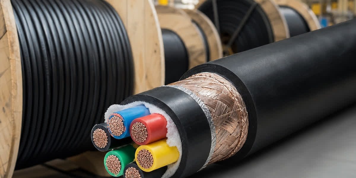
Un cable de control es un cable multiconductor diseñado para transmitir señales de control e instrumentación a baja tensión (normalmente 300/500 V, 450/750 V o 0,6/1 kV). Las construcciones más comunes son:
| Tipo | Construcción | Aplicación Típica |
|---|---|---|
| LiYY / YY | Aislamiento y cubierta de PVC, sin pantalla | Cableado interior de paneles, circuitos generales de control |
| LiYCY / CY | Aislamiento y cubierta de PVC, pantalla de trenza de cobre | Señales analógicas, señales de variadores de frecuencia |
| SY | Aislamiento y cubierta de PVC, pantalla de trenza de alambre de acero | Protección mecánica, tendidos exteriores y de planta |
| Cable de instrumentación (BS 5308) | Pares/tripletes trenzados, pantalla individual + global | RTD, termopares, lazos de 4-20 mA, bus de campo |
| Cable de control armado | Armadura de alambre o cinta de acero | Enterramiento directo, zonas de riesgo mecánico |
💡 Regla práctica: utilice cable apantallado (LiYCY/CY o tipo BS 5308) para cualquier señal analógica inferior a 1 V o cualquier recorrido superior a 30 m. El LiYY sin pantalla solo es aceptable para circuitos digitales cortos en interiores y circuitos de control de potencia.
2. Preparación Previa a la Instalación
2.1 Lista de Verificación de Recepción y Almacenamiento
| Verificación | Criterio de Aceptación |
|---|---|
| Estado de la bobina | Bridas sin daños; tapas de extremo colocadas y selladas |
| Inspección visual de la cubierta | Sin cortes, rozaduras ni aplastamientos; sin manchas de agua |
| Verificación de longitud | La longitud de la etiqueta coincide con el albarán |
| Prueba de aislamiento a la recepción | ≥ 100 MΩ a 500 V CC entre conductores y conductor-pantalla |
| Entorno de almacenamiento | Interior seco, 0–40 °C; bobinas sobre soportes, no en el suelo |
| Vida útil | Cubierta de PVC: almacenar dentro de 2 años desde la fabricación si hay exposición UV |
La humedad es el principal enemigo del cable de control. Si una bobina se ha almacenado al exterior sin tapas de extremo, no la instale hasta realizar una prueba completa de resistencia de aislamiento.
2.2 Lista de Verificación de Herramientas y Equipos
| Categoría | Elementos | Aplicación |
|---|---|---|
| Tendido | Rodillos, medias de tiro, eslabones giratorios, dinamómetro, lubricante | Tendido sin daños |
| Terminación | Pelacables, cortadores laterales, herramienta de engaste, destornillador dinamométrico, llaves de prensaestopas | Prensado y terminación |
| Pruebas | Megóhmetro de 500 V CC, multímetro, calibrador de lazo, comprobador de continuidad | Verificación posterior a la instalación |
| Seguridad | Kit LOTO, detector de tensión, EPI (guantes, gafas, calzado de seguridad) | Trabajo seguro |
2.3 Inspección de la Ruta y Plan de Tendido
Recorra la ruta antes del tendido. Compruebe la ocupación de las bandejas, las ubicaciones de las curvas, los puntos de cruce y el espacio disponible para el radio de curvatura mínimo. Marque los puntos de tiro y los rodillos intermedios. Para recorridos largos, planifique la dirección de tiro de modo que el cable salga por la parte superior de la bobina, nunca por la inferior, y que cada curva se aborde con suficiente tramo recto de entrada (al menos 10 veces el diámetro del cable).
3. Consideraciones de Ingeniería: Radio de Curvatura, Tensión de Tiro y Separación
3.1 Radio de Curvatura Mínimo
| Tipo de Cable | En Instalación | Durante el Tiro |
|---|---|---|
| Sin pantalla (LiYY, YY) | 6 × diámetro exterior | 10 × diámetro exterior |
| Apantallado (LiYCY, CY, SY) | 12 × diámetro exterior | 15 × diámetro exterior |
| Instrumentación BS 5308 | 12 × diámetro exterior | 15 × diámetro exterior |
| Armado | 12 × diámetro exterior | 15 × diámetro exterior |
Superar estos límites aplasta el paso de trenzado de los pares y la pantalla, aumentando el desequilibrio de capacidad y degradando permanentemente el rechazo al ruido.
3.2 Tensión de Tiro y Presión Lateral
La tensión máxima de tiro de un cable de control con conductores de cobre está limitada por los conductores:
T_máx = N × A × σ donde N = número de conductores, A = sección del conductor (mm²), σ = 34,5 MPa (5000 psi) para cobre.
Para un cable de 12 conductores × 1,5 mm²: T_máx = 12 × 1,5 × 34,5 ≈ 620 N (≈ 63 kg). No supere nunca este valor: tirar con más fuerza que el límite del conductor estira el cobre y crea fallos permanentes de resistencia y capacidad. Utilice un dinamómetro en cada tiro. Cuando el tiro calculado supere el límite, instale puntos de tiro intermedios o divida el tramo.
La presión lateral en cualquier curva debe mantenerse por debajo de 730 kg/m (500 lb/ft) según IEEE 1185; utilice rodillos de mayor radio o curvas suaves en cada cambio de dirección.
3.3 Separación de los Cables de Potencia
| Condición | Separación Mínima |
|---|---|
| Circuitos de clase 2/3 frente a conductores de potencia (NEC 725.136) | 50 mm (2 pulgadas) o barrera puesta a tierra |
| Cable de bandeja tipo ITC frente a potencia (NEC 727.4) | 50 mm (2 pulgadas) o barrera |
| Señal analógica frente a cable de potencia > 30 A | 300 mm recomendados |
| Recorrido paralelo a lo largo de pared/ducto, señales analógicas | 300 mm o partición de acero |
| Cruce a 90° | 50 mm (sin exposición paralela larga) |
El campo magnético de 50/60 Hz de un cable de potencia induce tensión en un lazo de control. Una separación de 300 mm reduce normalmente el ruido inducido por debajo del nivel de 1 mV requerido para señales analógicas fiables. Cuando la segregación sea imposible, tienda el cable de control en una bandeja o conducto de acero separado con un enlace continuo a tierra.
4. Procedimiento de Instalación Paso a Paso
Paso 1 — Prepare la ruta. Limpie la bandeja, coloque rodillos protectores en cada borde y curva, e instale rodillos de soporte intermedios cada 2–3 m en los tramos horizontales.
Paso 2 — Monte la bobina. Coloque la bobina sobre un gato con el cable saliendo por la parte superior. Un dispositivo de frenado evita el avance excesivo y el efecto serpenteante.
Paso 3 — Tienda el cable. Utilice una media de tiro sobre la cubierta (nunca tire de los conductores individuales), acople un eslabón giratorio, aplique lubricante aprobado y tire a velocidad constante de 5–15 m/min vigilando el dinamómetro. Deténgase inmediatamente si la tensión aumenta bruscamente.
Paso 4 — Acomodo y fijación. Tienda el cable con una holgura natural del 1–2% para absorber los movimientos térmicos. Fije con grapas o bridas a intervalos de 300 mm en tramos verticales y de 400–600 mm en tramos horizontales. No apriete en exceso las bridas: la deformación de la cubierta comprime los conductores.
Paso 5 — Prensado. Seleccione un prensaestopas acorde con la armadura/pantalla del cable (por ejemplo, prensaestopas certificados Ex d / Ex e en zonas peligrosas según IEC 60079-14). Pele la cubierta con un cuchillo de profundidad controlada, abanique la trenza de la pantalla sobre el cono del prensaestopas y apriete la tuerca al par del fabricante.
Paso 6 — Terminación. Pele 8–10 mm de aislamiento, engaste con el terminal tubular correcto (terminal de férula para conductores de varios hilos) y apriete los bornes al par especificado por el fabricante del panel. Deje los conductores de reserva claramente identificados y terminados o aislados individualmente.
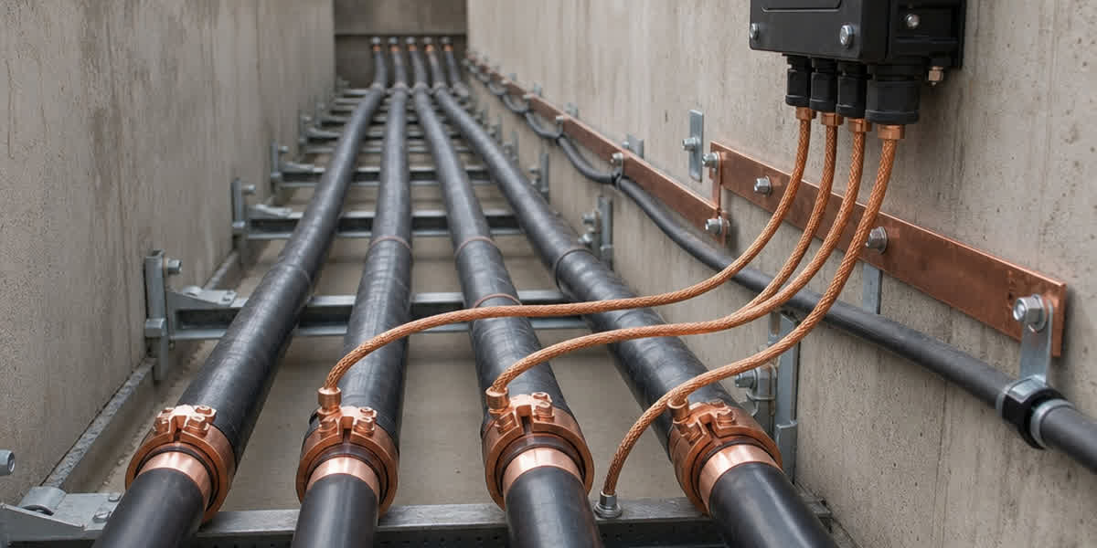
Paso 7 — Puesta a tierra de la pantalla. Conecte a tierra la pantalla del cable en un solo extremo — normalmente el extremo de la sala de control (receptor). Conectar ambos extremos crea un lazo que capta interferencias de 50/60 Hz. En el extremo de campo, aísle la pantalla y déjela flotante, o conéctela mediante un pequeño condensador (0,1 µF) si preocupa el ruido de alta frecuencia.
Paso 8 — Identificación. Coloque marcadores permanentes en ambos extremos, cada 10 m en las bandejas y en cada paso a través de muros. Registre los colores de los conductores y los números de bornes en el esquema de lazos.
⚠️ Seguridad: desconecte la tensión y aplique LOTO antes de cualquier trabajo de terminación. Las tensiones inducidas en recorridos paralelos largos pueden superar los 50 V incluso con el circuito sin tensión: compruebe antes de tocar.
5. Inspección y Pruebas Posteriores a la Instalación
| Prueba | Método | Criterio de Aceptación |
|---|---|---|
| Resistencia de aislamiento | Megóhmetro de 500 V CC, conductor-conductor y conductor-pantalla, 1 minuto | ≥ 100 MΩ por km en instalación nueva; lecturas típicas 1–10 GΩ |
| Continuidad de la pantalla | Óhmetro de baja resistencia extremo a extremo | ≤ 1 Ω por cada 100 m para trenza de cobre |
| Continuidad de los conductores | Comprobador de continuidad en cada conductor | 0 Ω (dentro de la precisión del instrumento); coherente con el esquema |
| Polaridad / identificación | Verificación de cada conductor contra el esquema | Sin conductores cruzados |
| Unión a tierra | Resistencia de la pantalla a tierra de planta en el extremo de control | < 1 Ω |
Registre todas las lecturas y consérvelas para comparar tendencias: la tendencia es más valiosa que el valor absoluto. Una caída del 30% en la resistencia de aislamiento entre dos pruebas anuales es una alerta temprana incluso cuando la lectura sigue por encima del límite de aceptación.
6. Programa de Mantenimiento Rutinario
| Frecuencia | Actividad |
|---|---|
| Mensual | Inspección visual de los tramos expuestos; comprobar apriete de prensaestopas y bridas |
| Trimestral | Termografía infrarroja de las terminaciones: un borne más de 10 °C por encima de la ambiente indica conexión floja |
| Semestral | Prueba de aislamiento de 500 V CC en lazos críticos; comparar con la línea base |
| Anual | Verificación de continuidad de la pantalla; revisión del par de los bornes del panel; calibración de lazos analógicos |
| Cada 3–5 años | Prueba completa de resistencia de aislamiento y análisis de tendencias; sustituir cables con cubierta agrietada o fragilizada |
7. Resolución de Problemas Comunes
| Problema | Causa Probable | Solución |
|---|---|---|
| Zumbido de 50/60 Hz en señal analógica | Pantalla puesta a tierra en ambos extremos (lazo de tierra) | Convertir a puesta a tierra en un solo punto; comprobar uniones |
| Señal intermitente / deriva | Terminación floja o contacto corroído | Re-terminar con férulas nuevas; apretar al par especificado |
| Diafonía entre pares | Capacidad excesiva o acoplamiento apretado de pares | Aumentar la separación; verificar el trenzado en las terminaciones |
| Baja resistencia de aislamiento | Entrada de humedad en el prensaestopas o cubierta dañada | Sustituir los sellos; secar y volver a probar; reparar o sustituir la cubierta |
| Cable caliente / caída de tensión en la carga | Conductor de sección insuficiente para la carga de control | Verificar la corriente de carga; aumentar la sección del conductor |
| Trenza de la pantalla corroída | Atmósfera agresiva (cloruros, H₂S) | Utilizar trenza de cobre estañado o versión armada |
| Cubierta agrietada | Exposición a rayos UV o productos químicos | Utilizar cubierta LSZH/PE resistente a UV o tender en conducto |
| Tensión inducida en conductores de reserva | Recorrido paralelo largo con cables de potencia | Poner a tierra los conductores de reserva en un extremo; aumentar la separación |
8. Consideraciones de Seguridad
| Peligro | Precauciones |
|---|---|
| Tensión inducida en recorridos largos | Comprobar y poner a tierra antes de manipular; tratar todos los conductores como vivos |
| Circuitos con tensión durante la terminación | Desconectar, aplicar LOTO y verificar con detector de tensión |
| Atmósferas explosivas (zonas Ex) | Prensado y terminaciones certificados según IEC 60079-14; permiso de trabajo en caliente |
| Bobinas pesadas y tiros largos | Ayudas mecánicas de manipulación; regla de dos personas; no tirar a mano sobre bordes |
| Bordes afilados de bandejas y polvo de cobre | Guantes, gafas y mangas largas; lavarse las manos después de manipular |
| Espacios confinados (zanjas, fosas) | Prueba de gases, ventilación y persona de vigilancia antes de entrar |
9. Preguntas Frecuentes (FAQ)
P1: ¿Por qué la pantalla del cable de control debe ponerse a tierra en un solo extremo? Poner a tierra ambos extremos crea un lazo cerrado por el que el campo magnético de los cables de potencia cercanos induce una corriente circulante de 50/60 Hz — exactamente la interferencia que la pantalla debe detener. La puesta a tierra en un solo punto, normalmente en el extremo de la sala de control, drena el ruido capacitivo a tierra manteniendo el lazo abierto. Las aplicaciones de alta frecuencia (bus de campo, Ethernet) son la excepción en la que a veces se conectan ambos extremos para controlar las emisiones radiadas.
P2: ¿Cuál es el radio de curvatura mínimo del cable de control? Cable sin pantalla: 6× el diámetro exterior (10× durante el tiro). Cable apantallado y armado: 12× el diámetro exterior (15× durante el tiro). Curvar más de lo permitido aplasta la pantalla y el trenzado de forma permanente, aumentando la capacidad y reduciendo la inmunidad al ruido.
P3: ¿A qué distancia debe mantenerse el cable de control de los cables de potencia? NEC 725.136 y NEC 727.4 exigen una separación mínima de 50 mm (2 pulgadas) de los conductores de potencia, salvo que se utilice una barrera puesta a tierra. Para señales analógicas en paralelo con circuitos de más de 30 A se recomiendan 300 mm de separación para mantener el ruido inducido por debajo de aproximadamente 1 mV.
P4: ¿Qué resistencia de aislamiento es aceptable en un cable de control nuevo? Una instalación nueva debe medir al menos 100 MΩ por km a 500 V CC; los cables sanos suelen dar lecturas de 1–10 GΩ. Lo más importante es la coherencia entre conductores y la tendencia en el tiempo: una caída anual del 30% indica humedad o degradación del aislamiento en desarrollo.
P5: ¿Puede el cable de control compartir bandeja con cables de potencia? Solo con la segregación adecuada: una partición metálica puesta a tierra, o una separación mínima de 50 mm en bandeja ventilada, manteniendo la ocupación por debajo del 50% de la sección de la bandeja según NEC 392.22. Los cables de control analógicos y digitales no deben compartir compartimento con cables de más de 30 A salvo que estén apantallados y con puesta a tierra en un solo punto.
10. Referencias y Normas
| Norma | Descripción |
|---|---|
| IEC 60228 | Conductores de cables aislados — clases de conductores y resistencia |
| IEC 60227 | Cables aislados con PVC, tensiones nominales hasta 450/750 V |
| IEC 60502-1 | Cables de potencia con aislamiento extruido, 1 kV y 3 kV (clase 0,6/1 kV) |
| BS 5308 | Cables de instrumentación — pares/tripletes trenzados apantallados |
| UL 13 | Cable de circuito de potencia limitada |
| UL 1277 | Cable de bandeja (tipo TC) |
| NEC 725, 727, 392 | Circuitos de clase 2/3, tipo ITC, ocupación de bandejas |
| IEEE 383 | Ensayo de llama para cables en plantas industriales/nucleares |
| IEEE 1185 | Guía de tendido e instalación de cables |
| IEC 60332-1/-3 | Ensayos de propagación de llama (individual y en haz) |
| IEC 61034 / IEC 60754 | Densidad de humo y contenido de halógenos |
| IEC 60079-14 | Instalaciones eléctricas en atmósferas explosivas |
| ICEA S-73-532 | Norma de cables de control e instrumentación |
| EN 50288 | Cables de elementos metálicos múltiples para señales analógicas/digitales |
11. Acerca de SiTong Cable
SiTong Cable fabrica cables de control e instrumentación según normas IEC, BS, UL y ASTM, con cubiertas de PVC, PE y LSZH, pantallas de trenza de cobre o cobre estañado, y armadura opcional de alambre de acero — suministrados en bobinas de grado exportación con certificados de ensayo completos. Nuestros ingenieros pueden ayudarle a seleccionar la construcción adecuada para su proceso, distribución de planta y condiciones ambientales.
👉 Explore nuestra gama de productos de Cable de Control 👉 Cable de Control (Instrumentación y Control): Guía Técnica Completa — Normas, Especificaciones, Selección 👉 Contacte con nuestro equipo
📬 Consultas de ventas: sales@sitongcable.com | 📞 Teléfono: +86-371-69176007
Esta guía fue preparada por el equipo de ingeniería de SiTong Cable. Todos los datos técnicos hacen referencia a las normas enumeradas en la Sección 10.